Binary Exponential
Backoff
Sendersends immediately with idle channel
Continues to listen while transmitting
In case of a collision, the sender waits for a
random period (maximum of two time slots)
In case they collide again, the interval is just
doubled every time it experiences a collision
When doubling is repeated to the slot size to
0–1023 it will not increase further
5.
Time isdivided into discrete slots whose length is equal to the worst-case round-trip
propagation time on the either (2τ).
minimum frame is 64 bytes (header + 46 bytes of data) = 512 bits
Channel capacity 10 Mbps, 512/10 M = 51.2µ
After 1st
collision, each station waits for 0 or 1 time slot before trying again.
After 2nd
collision, each station picks up either 0,1,2 or 3 at random and waits for that
much time slots.
If 3rd
collision occurs, then next time number of slots to wait is chosen randomly from
interval 0 to 23
-1.
In general, after ith
collision, random number between 0 to 2i
-1 is chosen, that
number of time slot is skipped.
After 10th
collision, randomized interval is frozen at max of 1023 slots.
After 16th
collision, controller reports failure back to computer sending and further
recovery is upto higher layers.
This algorithm is called Binary Exponential Back off Algorithm.
Advantage: Ensures a low delay when only a few stations collide, but also assures that
the collision is resolved in a reasonable interval when many stations collide.
Disadvantage: Could introduce significant delay.
Binary Exponential Back off
Algorithm
6.
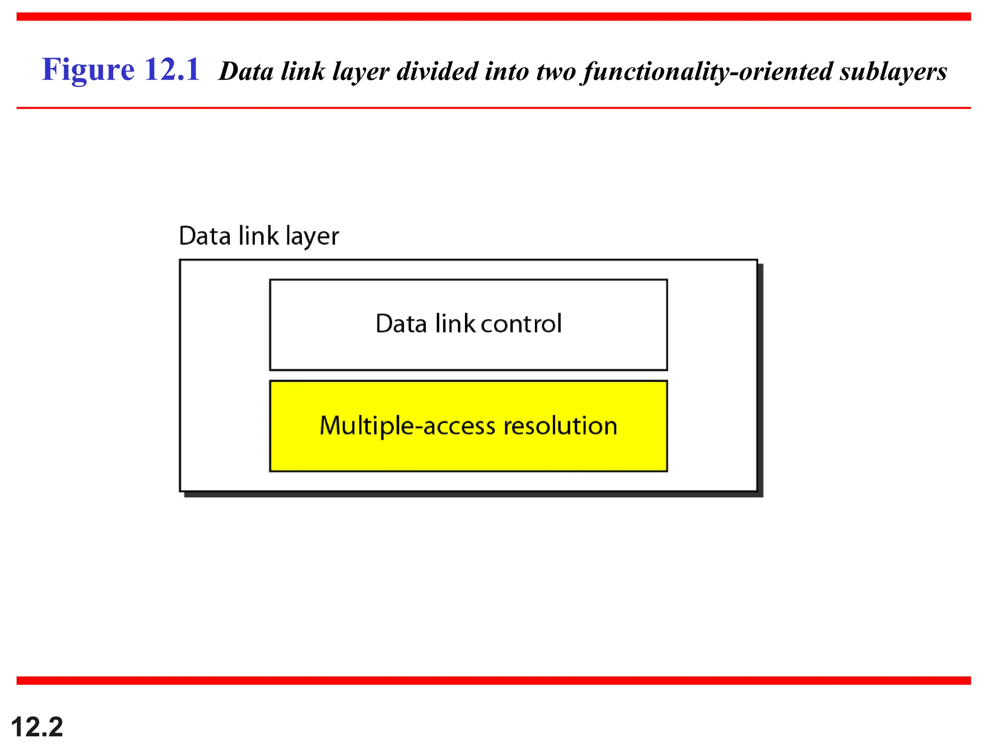
12.6
12-1 RANDOM ACCESS
12-1RANDOM ACCESS
In
In random access
random access or
or contention
contention methods, no station is
methods, no station is
superior to another station and none is assigned the
superior to another station and none is assigned the
control over another. No station permits, or does not
control over another. No station permits, or does not
permit, another station to send. At each instance, a
permit, another station to send. At each instance, a
station that has data to send uses a procedure defined
station that has data to send uses a procedure defined
by the protocol to make a decision on whether or not to
by the protocol to make a decision on whether or not to
send.
send.
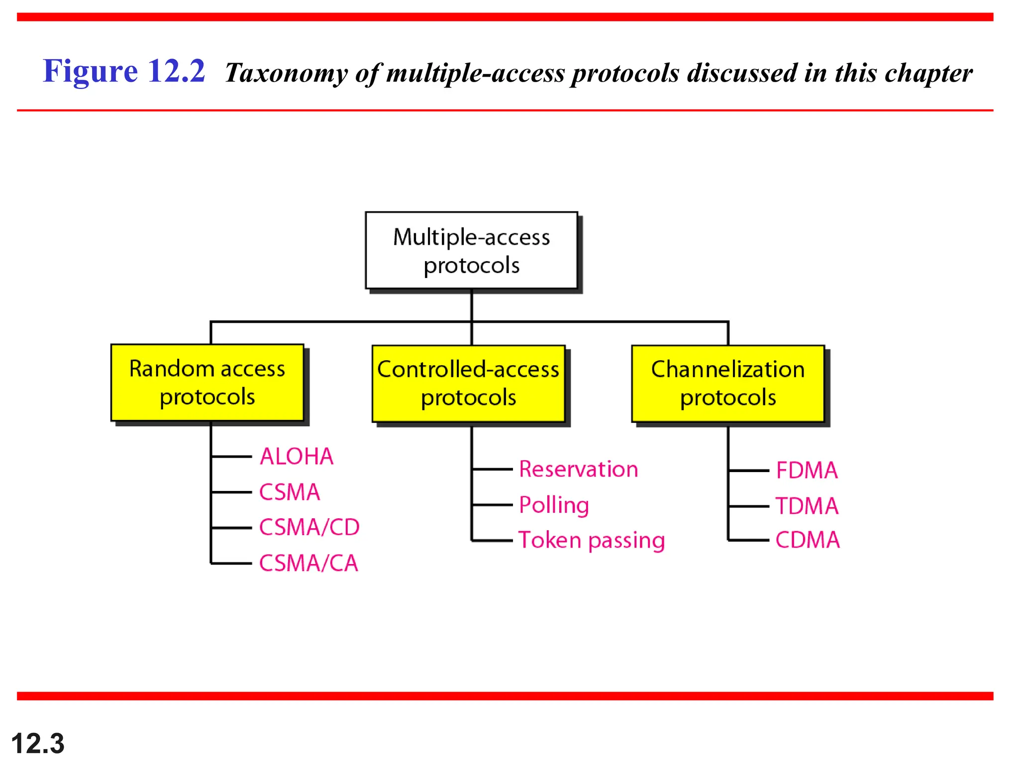
ALOHA
Carrier Sense Multiple Access
Carrier Sense Multiple Access with Collision Detection
Carrier Sense Multiple Access with Collision Avoidance
Topics discussed in this section:
Topics discussed in this section:
7.
ALOHA
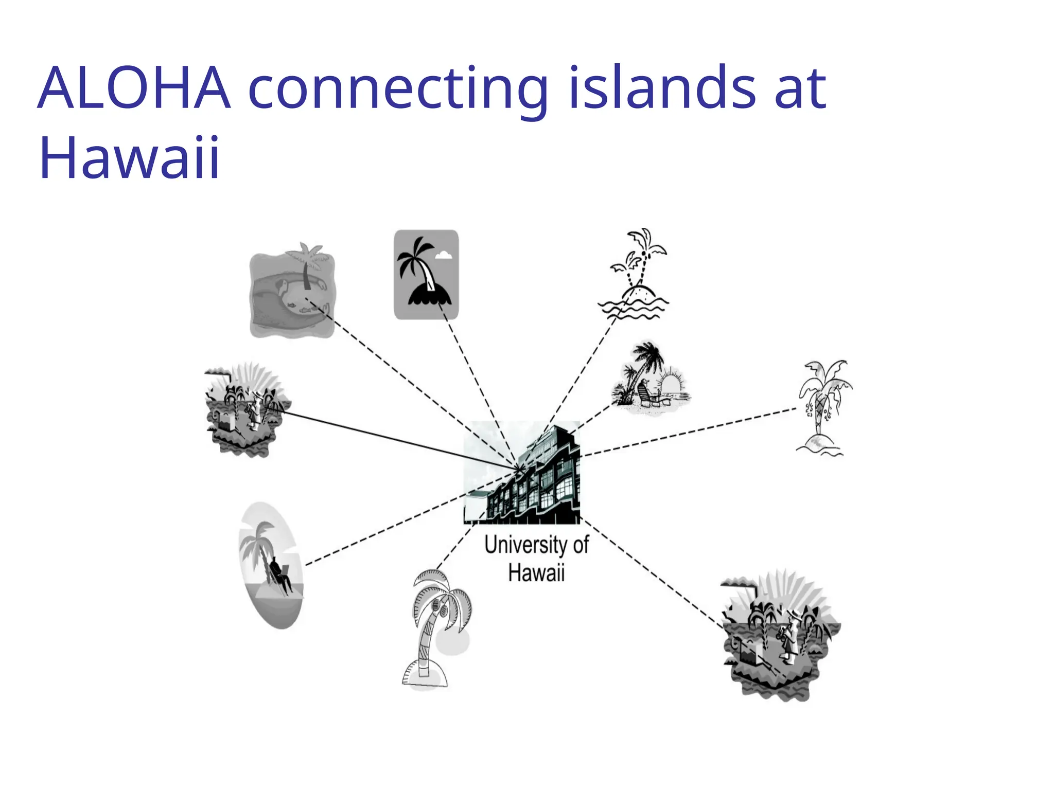
Norman Abramsonat University of Hawaii, in 70’s wanted to connect computer
centers of all the islands of Hawaii.
Hawaii is a collection of islands and it was not possible to connect them with
telephone lines.
Joining islands with wires laid on seabed was very expensive, so they started
thinking about wireless solution.
Solution: ALOHA
Using short range radios.
Half duplex by nature. At a time, only can send or receiver. Switching also
takes time.
Two different frequencies, one for sending, another for receiving.
But, problem of collision, how to solve it?
Solution: Let the users communicate, if signals collide, not acknowledged
and so, sender resends data.
Adding randomness reduces the chance of collision.
Algorithm is called Binary Exponential Back-off Algorithm.
Also had problem: While transmitting, sender can not sense collision.
In ALOHA, maximum 18 out of 100 packets pass without collision if
ALOHA works with optimum speed.
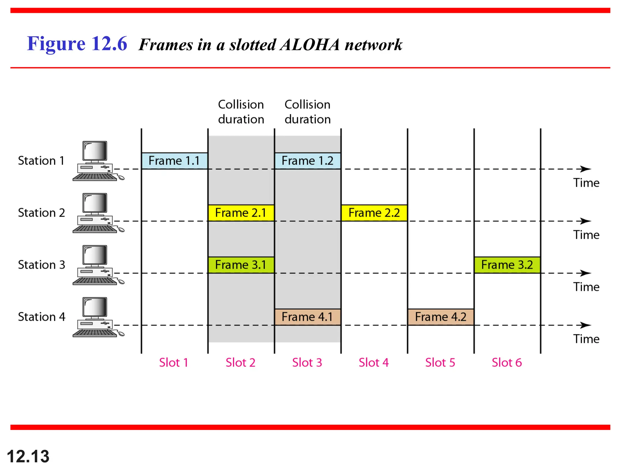
Slotted ALOHA
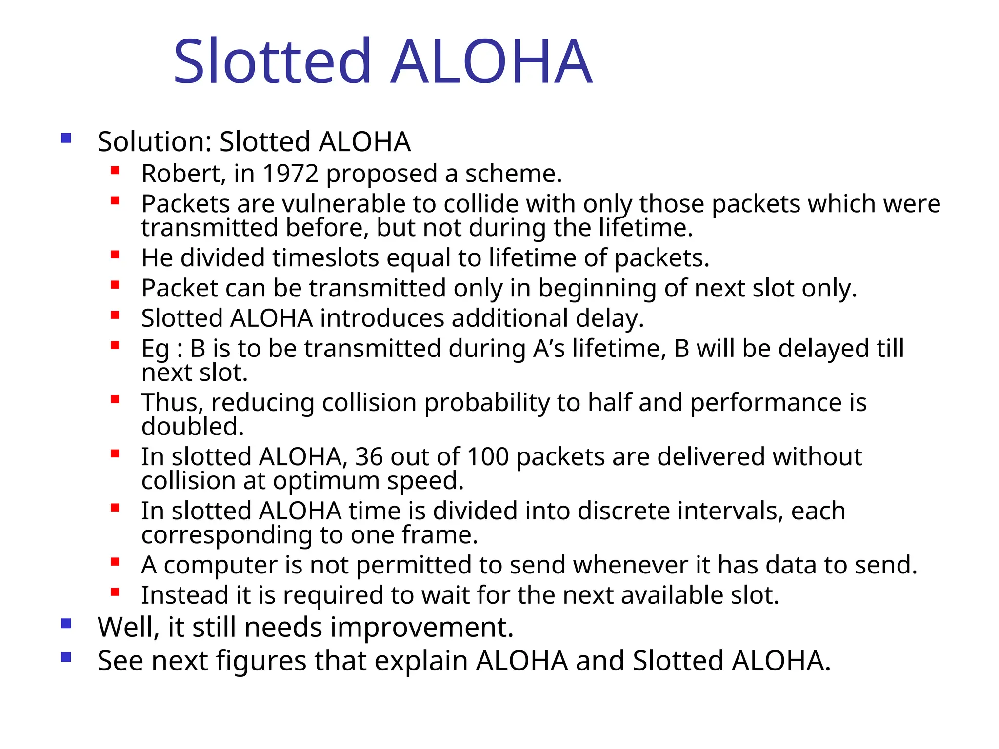
Solution:Slotted ALOHA
Robert, in 1972 proposed a scheme.
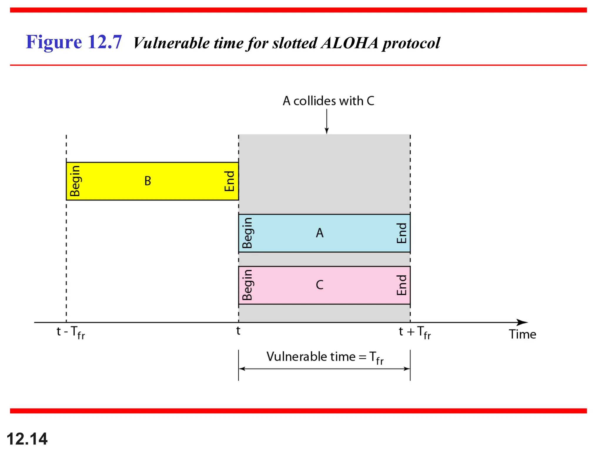
Packets are vulnerable to collide with only those packets which were
transmitted before, but not during the lifetime.
He divided timeslots equal to lifetime of packets.
Packet can be transmitted only in beginning of next slot only.
Slotted ALOHA introduces additional delay.
Eg : B is to be transmitted during A’s lifetime, B will be delayed till
next slot.
Thus, reducing collision probability to half and performance is
doubled.
In slotted ALOHA, 36 out of 100 packets are delivered without
collision at optimum speed.
In slotted ALOHA time is divided into discrete intervals, each
corresponding to one frame.
A computer is not permitted to send whenever it has data to send.
Instead it is required to wait for the next available slot.
Well, it still needs improvement.
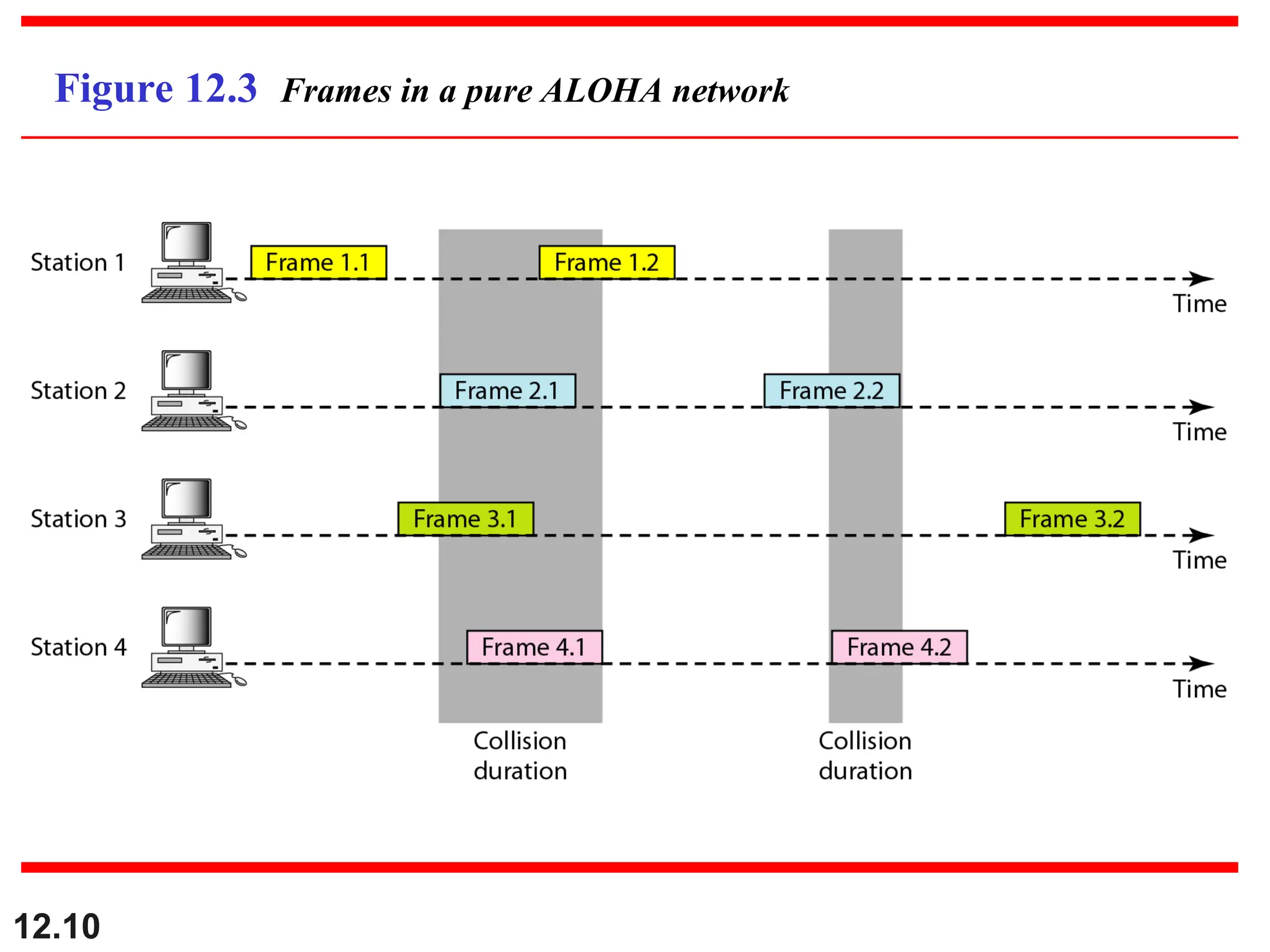
See next figures that explain ALOHA and Slotted ALOHA.
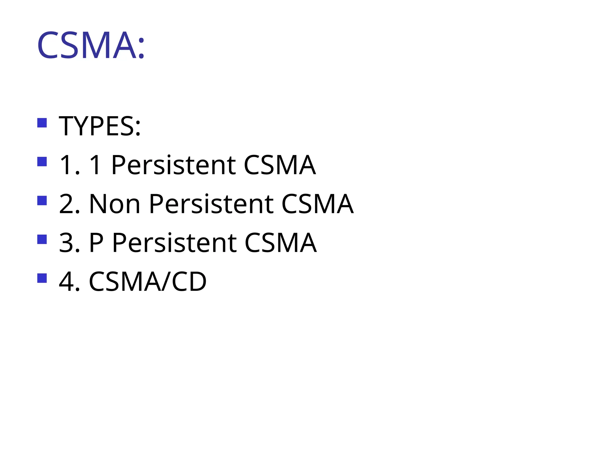
CSMA:
TYPES:
1.1 Persistent CSMA
2. Non Persistent CSMA
3. P Persistent CSMA
4. CSMA/CD
20.
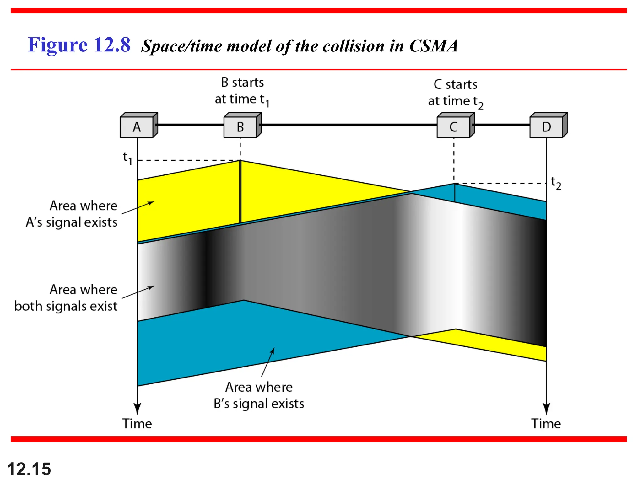
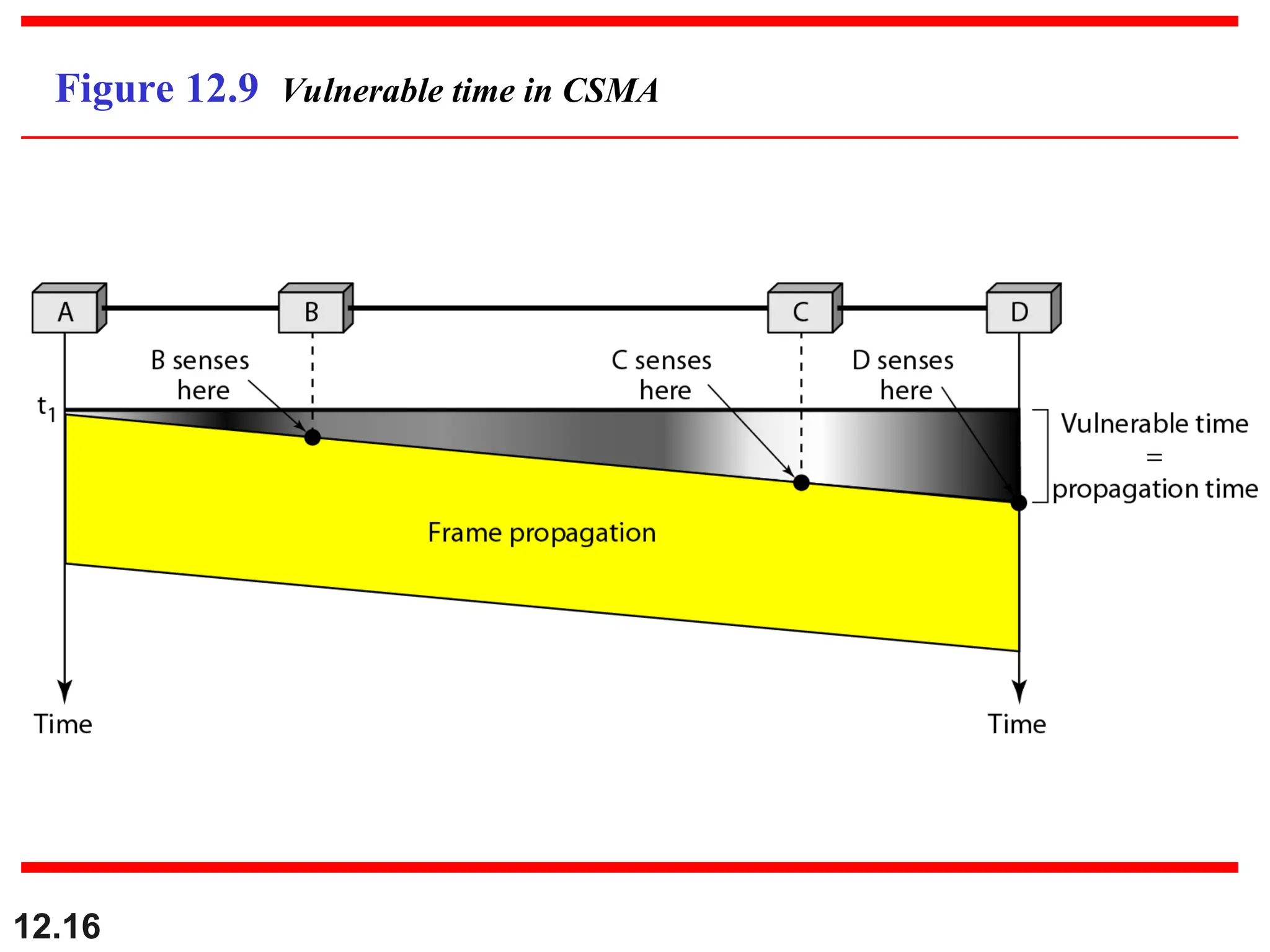
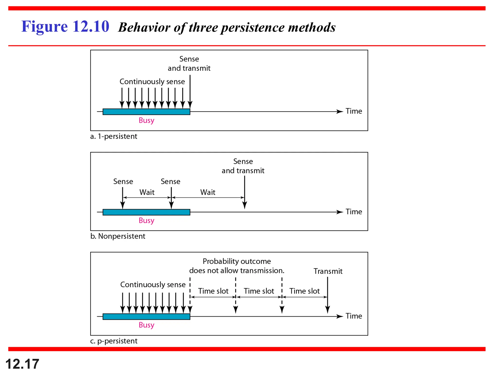
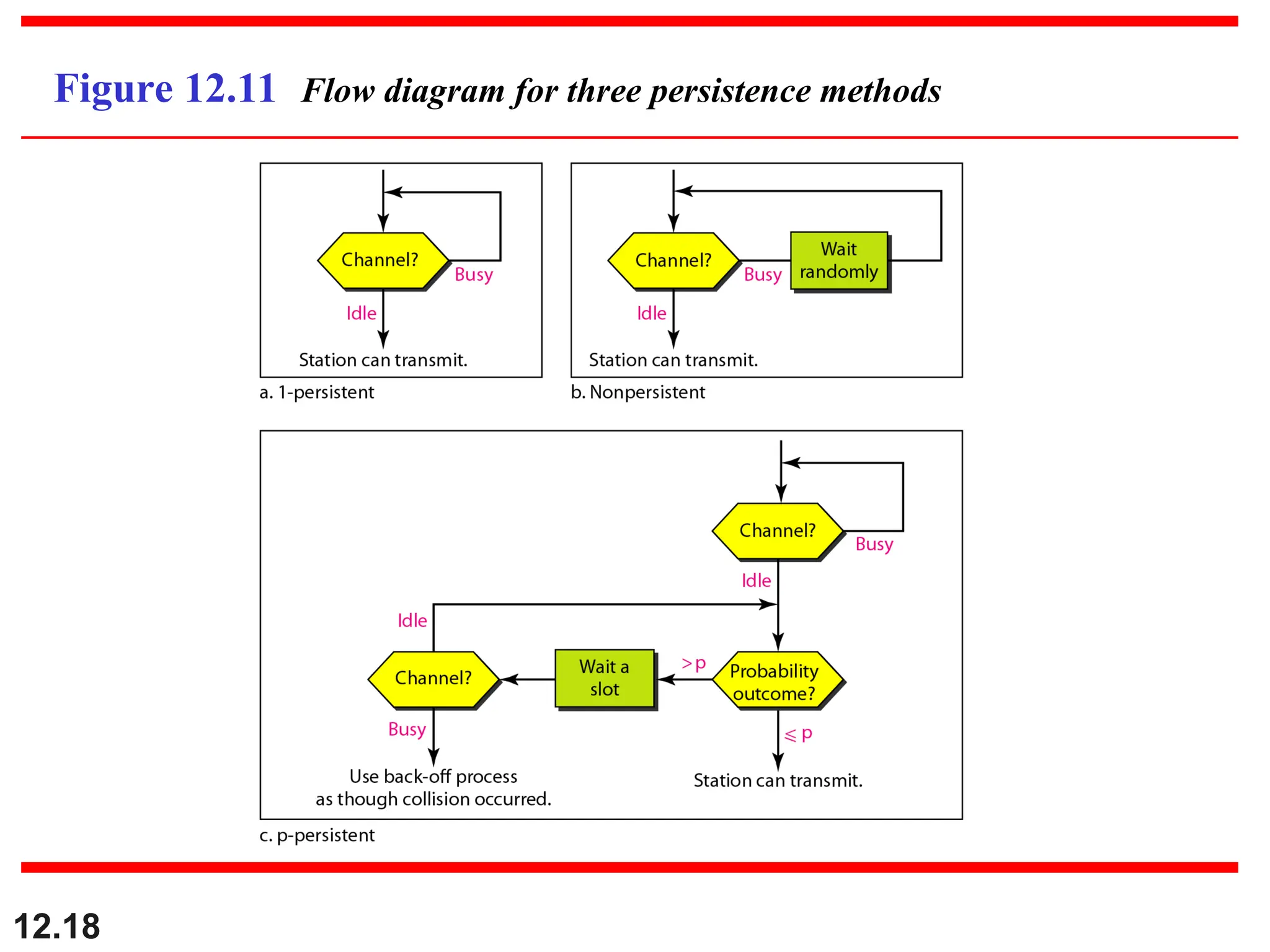
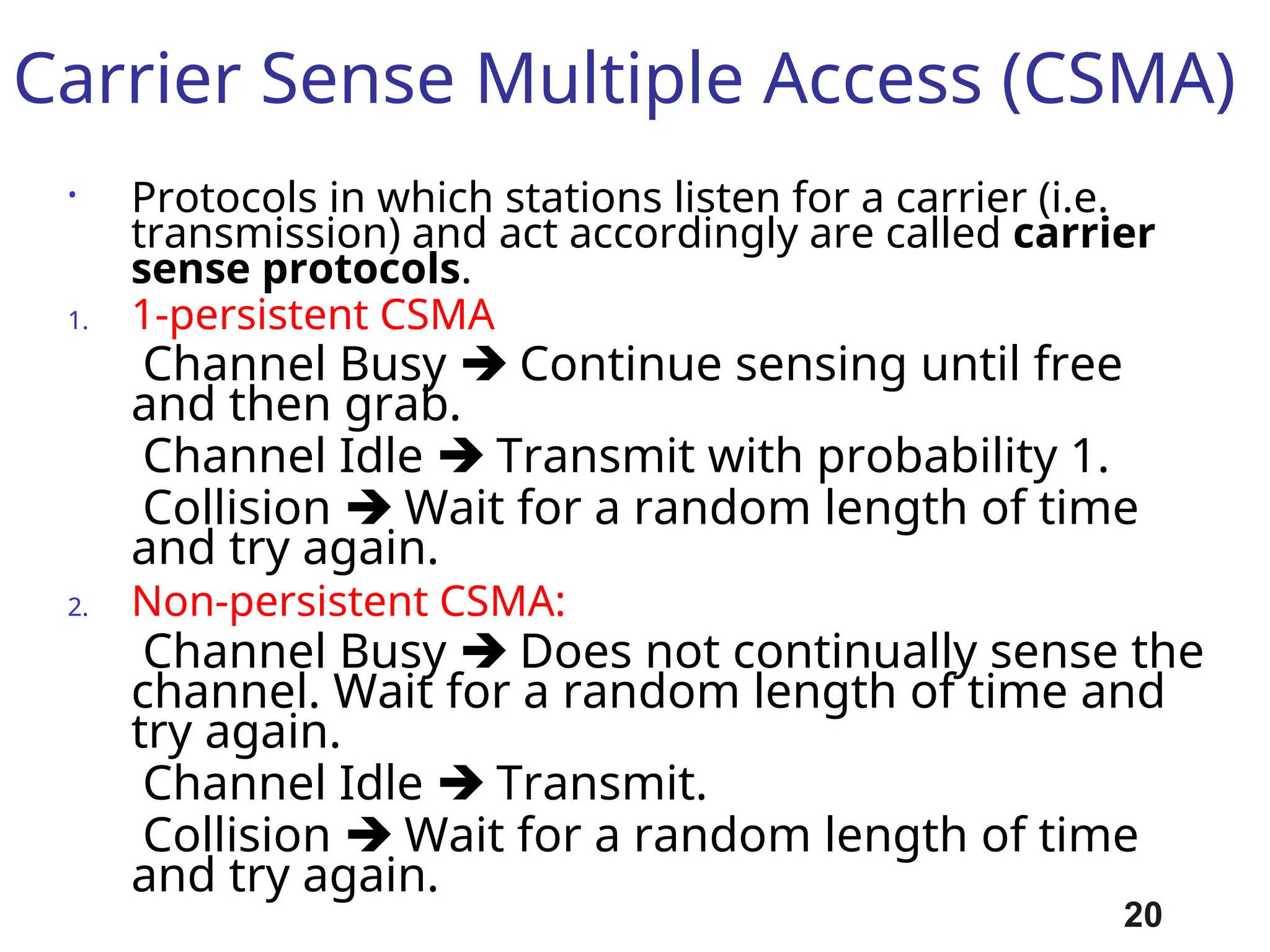
Carrier Sense MultipleAccess (CSMA)
• Protocols in which stations listen for a carrier (i.e.
transmission) and act accordingly are called carrier
sense protocols.
1. 1-persistent CSMA
Channel Busy Continue sensing until free
and then grab.
Channel Idle Transmit with probability 1.
Collision Wait for a random length of time
and try again.
2. Non-persistent CSMA:
Channel Busy Does not continually sense the
channel. Wait for a random length of time and
try again.
Channel Idle Transmit.
Collision Wait for a random length of time
and try again.
20
21.
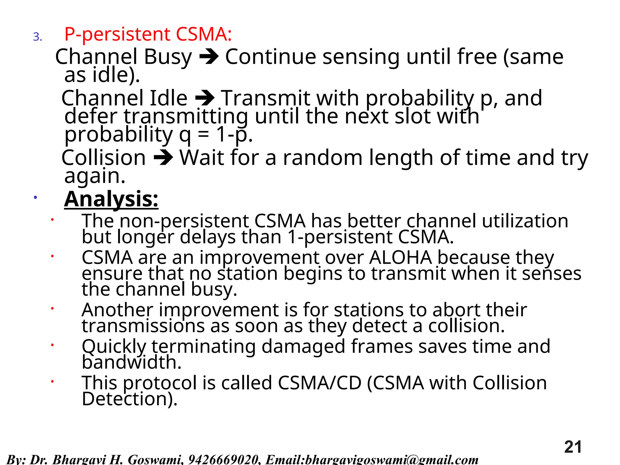
3. P-persistent CSMA:
ChannelBusy Continue sensing until free (same
as idle).
Channel Idle Transmit with probability p, and
defer transmitting until the next slot with
probability q = 1-p.
Collision Wait for a random length of time and try
again.
• Analysis:
• The non-persistent CSMA has better channel utilization
but longer delays than 1-persistent CSMA.
• CSMA are an improvement over ALOHA because they
ensure that no station begins to transmit when it senses
the channel busy.
• Another improvement is for stations to abort their
transmissions as soon as they detect a collision.
• Quickly terminating damaged frames saves time and
bandwidth.
• This protocol is called CSMA/CD (CSMA with Collision
Detection).
21
By: Dr. Bhargavi H. Goswami, 9426669020, Email:bhargavigoswami@gmail.com
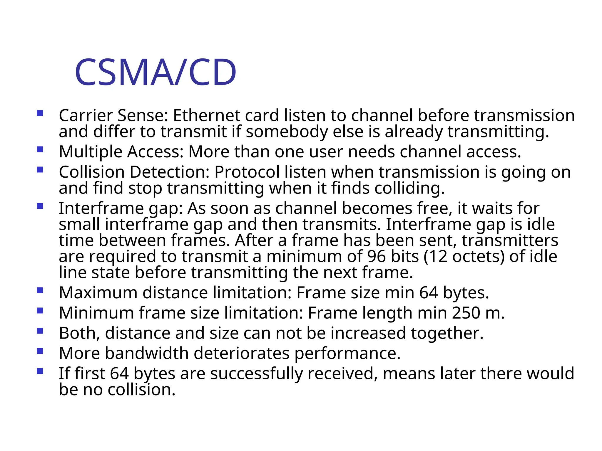
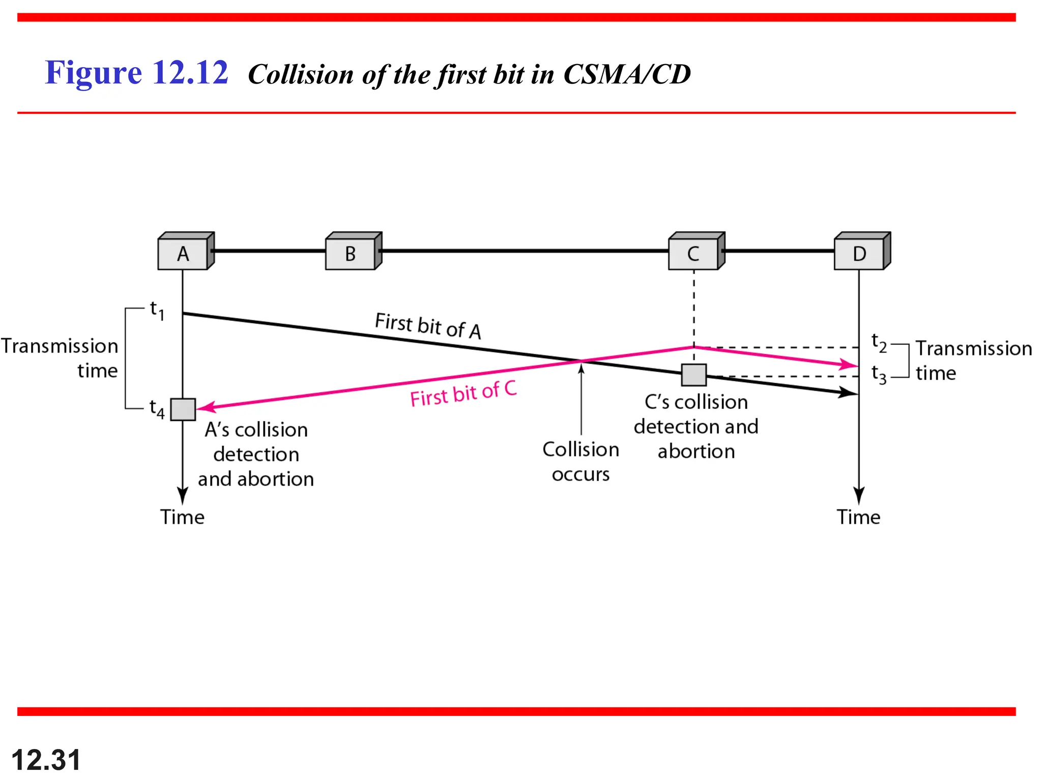
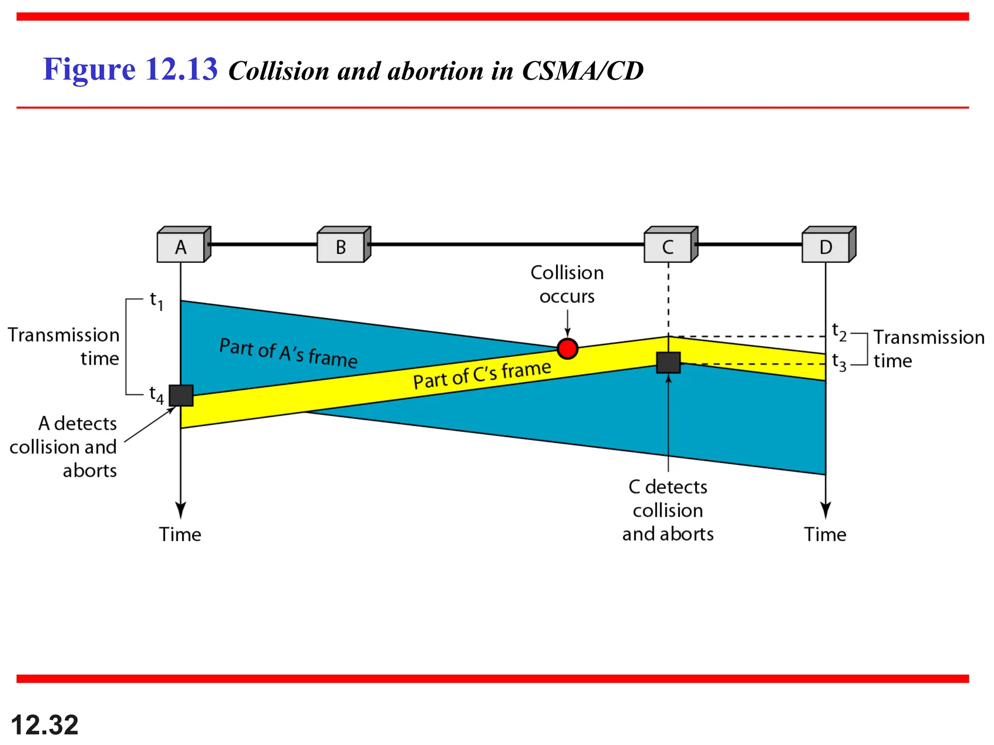
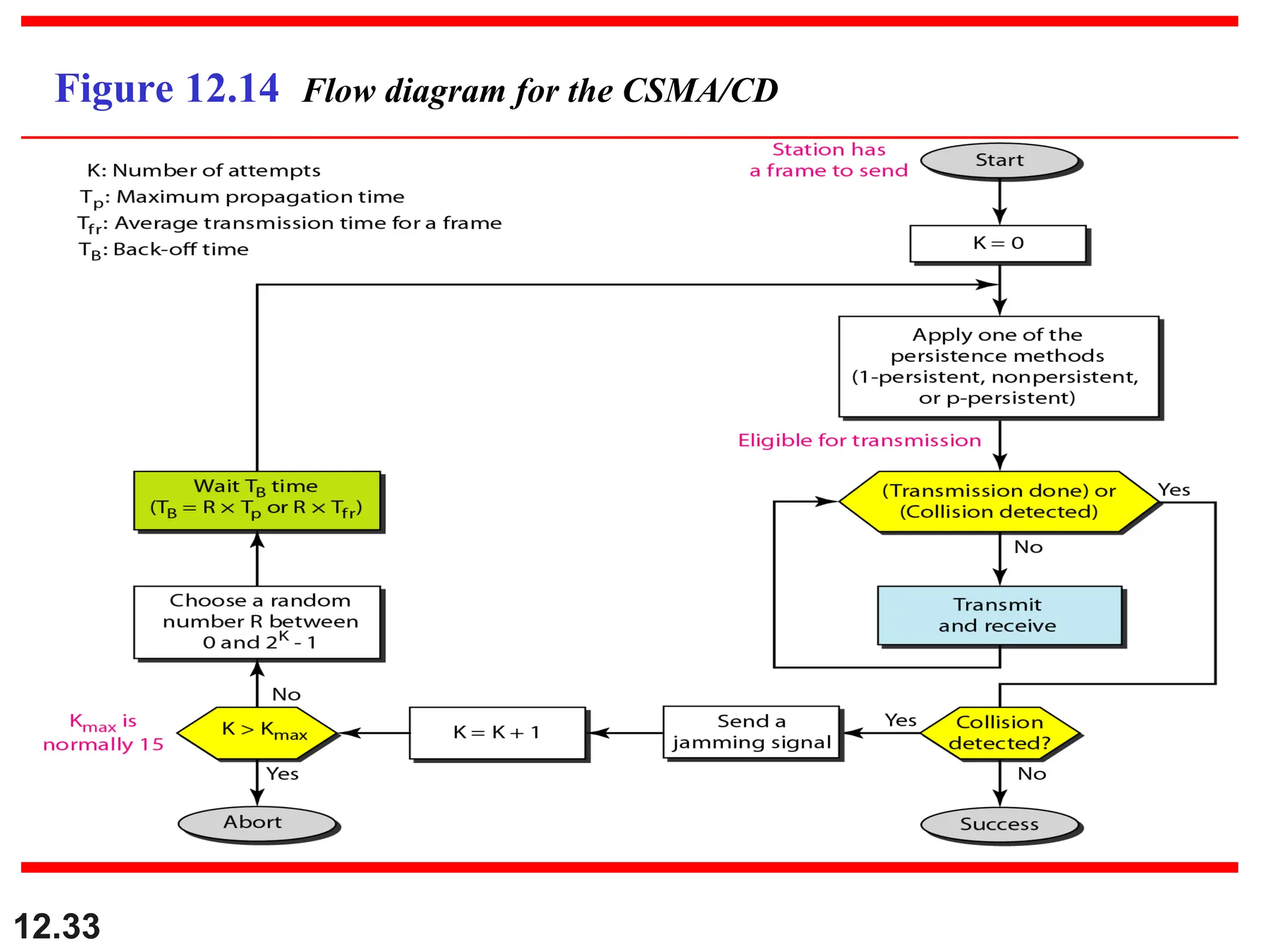
CSMA/CD
Carrier Sense:Ethernet card listen to channel before transmission
and differ to transmit if somebody else is already transmitting.
Multiple Access: More than one user needs channel access.
Collision Detection: Protocol listen when transmission is going on
and find stop transmitting when it finds colliding.
Interframe gap: As soon as channel becomes free, it waits for
small interframe gap and then transmits. Interframe gap is idle
time between frames. After a frame has been sent, transmitters
are required to transmit a minimum of 96 bits (12 octets) of idle
line state before transmitting the next frame.
Maximum distance limitation: Frame size min 64 bytes.
Minimum frame size limitation: Frame length min 250 m.
Both, distance and size can not be increased together.
More bandwidth deteriorates performance.
If first 64 bytes are successfully received, means later there would
be no collision.
24.
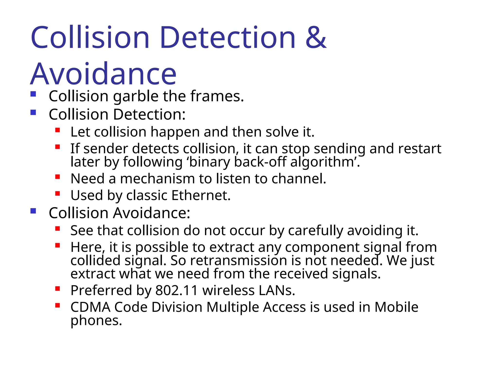
Collision Detection &
Avoidance
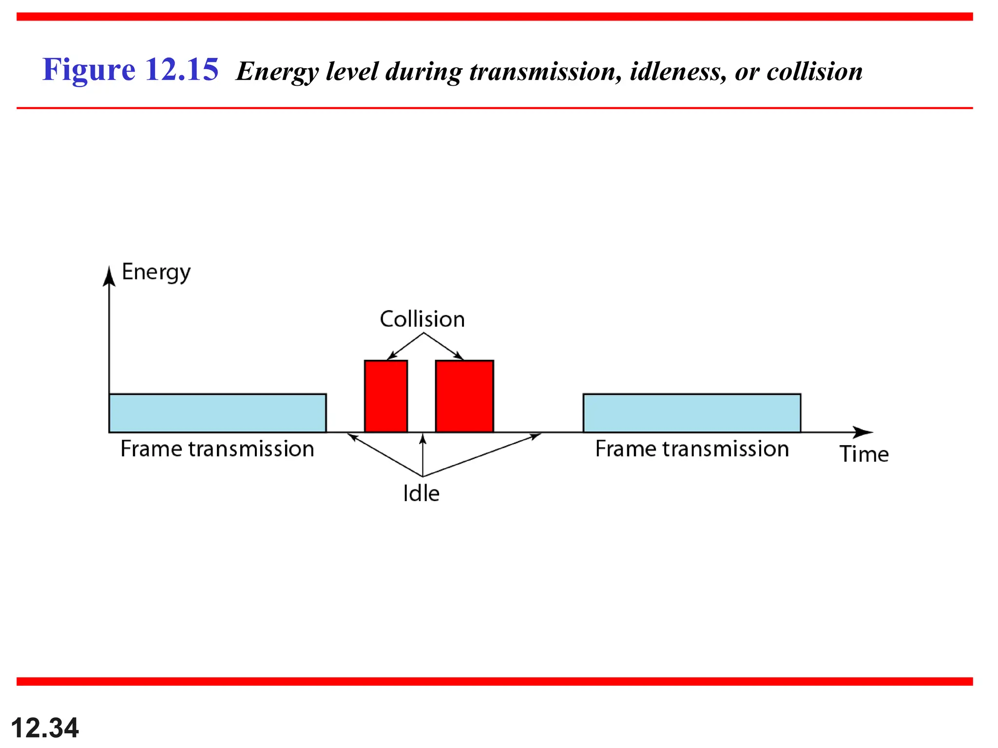
Collision garble the frames.
Collision Detection:
Let collision happen and then solve it.
If sender detects collision, it can stop sending and restart
later by following ‘binary back-off algorithm’.
Need a mechanism to listen to channel.
Used by classic Ethernet.
Collision Avoidance:
See that collision do not occur by carefully avoiding it.
Here, it is possible to extract any component signal from
collided signal. So retransmission is not needed. We just
extract what we need from the received signals.
Preferred by 802.11 wireless LANs.
CDMA Code Division Multiple Access is used in Mobile
phones.
25.
CSMA/CA
Collision Avoidancewith Career Sense
Multiple Access.
On Wireless Networks
Strategies:
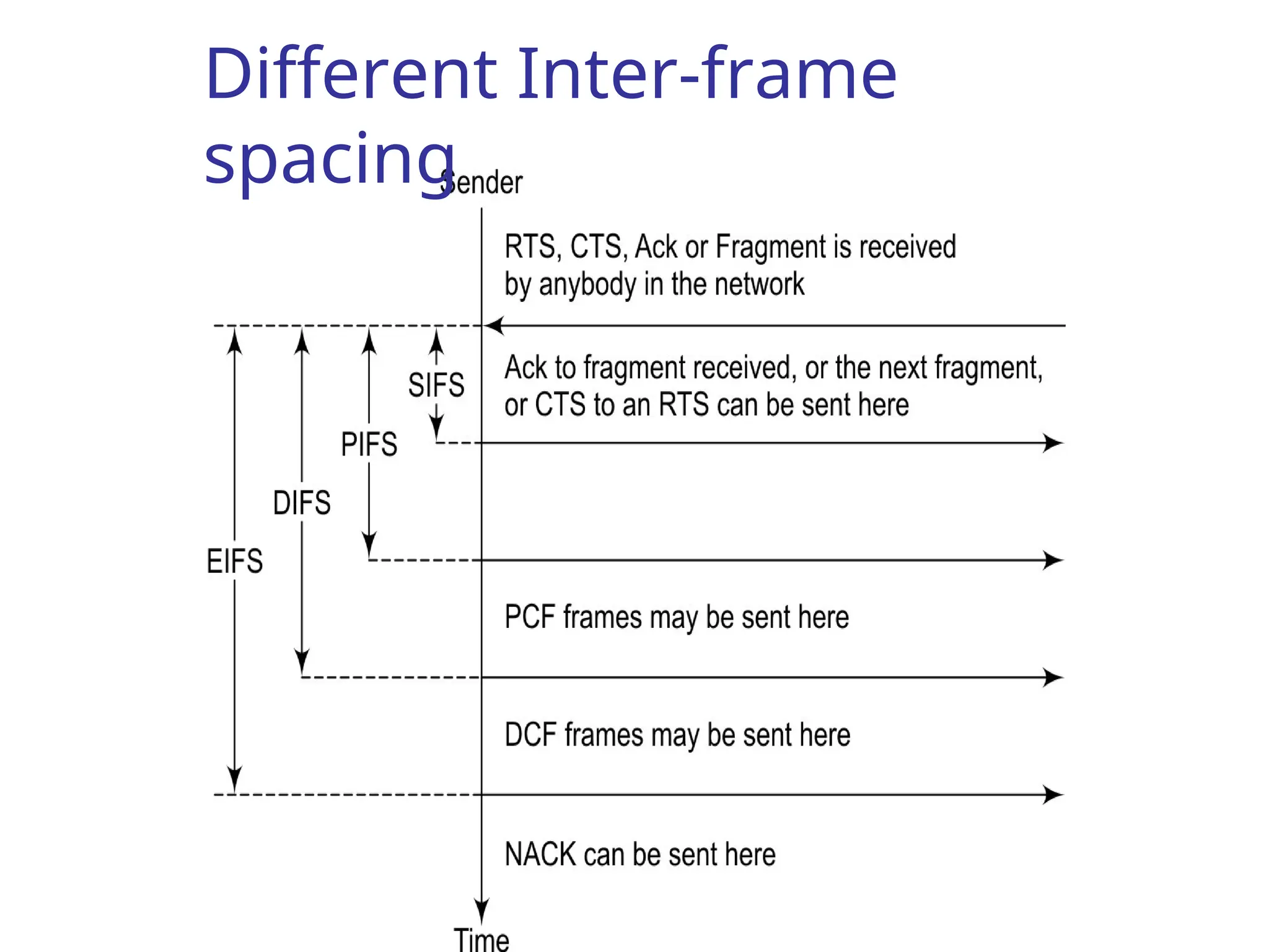
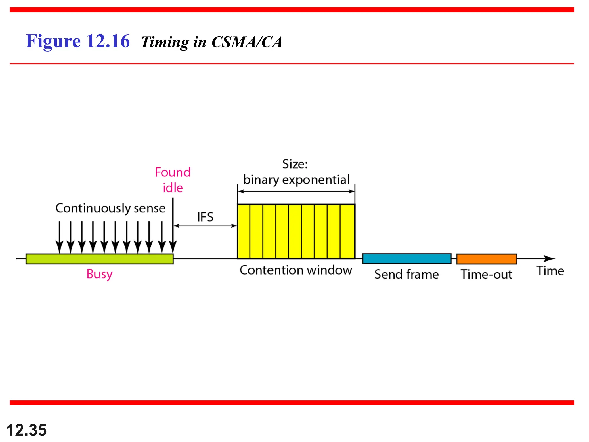
1. Inter-frame Spacing (IFS)
2. Contention Window – Binary Exponential
Back off Algorithm
3. Acknowledgement
26.
• Because signalstrength is not uniform
throughout the space in which wireless LANs
operate, carrier detection and collision may
fail in the following ways:
- Hidden nodes:
Hidden stations: Carrier sensing may fail to detect another
station. For example, A and D.
Fading: The strength of radio signals diminished rapidly with
the distance from the transmitter. For example, A and C.
- Exposed nodes:
Exposed stations: B is sending to A. C can detect it. C might
want to send to E but conclude it cannot transmit because C
hears B.
Collision masking: The local signal might drown out the
remote transmission.
• The result scheme is carrier sensing multiple
access with collision avoidance (CSMA/CA).
Wireless LAN Protocol
26
27.
Wireless LAN Protocols
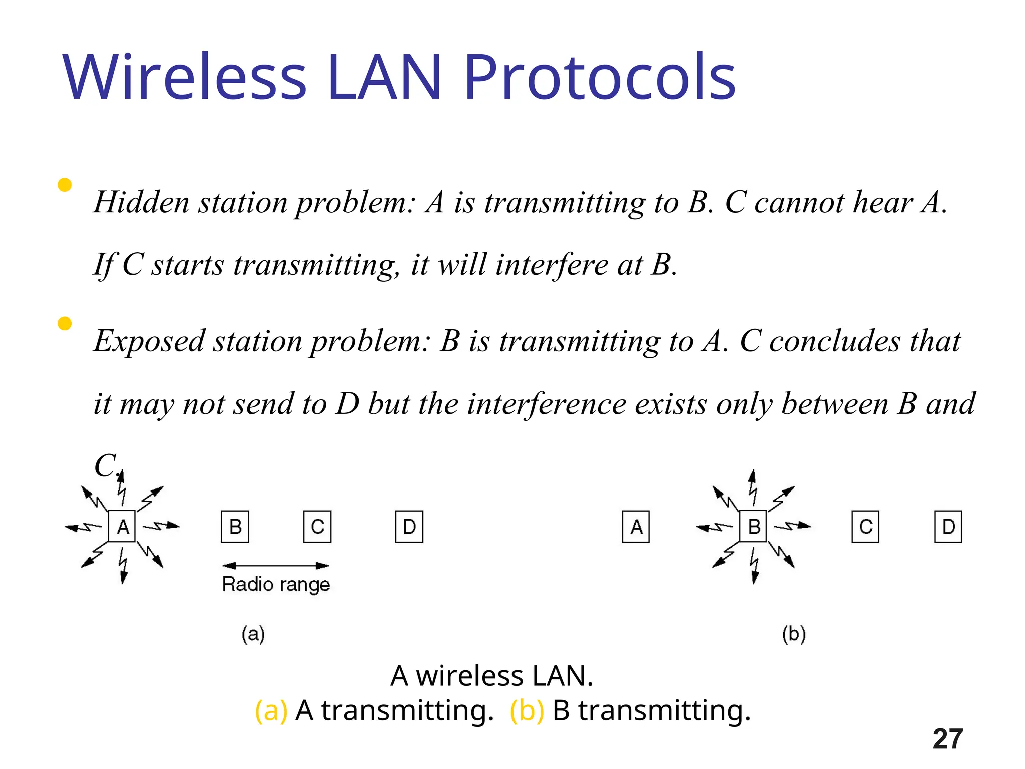
Awireless LAN.
(a) A transmitting. (b) B transmitting.
• Hidden station problem: A is transmitting to B. C cannot hear A.
If C starts transmitting, it will interfere at B.
• Exposed station problem: B is transmitting to A. C concludes that
it may not send to D but the interference exists only between B and
C.
27
28.
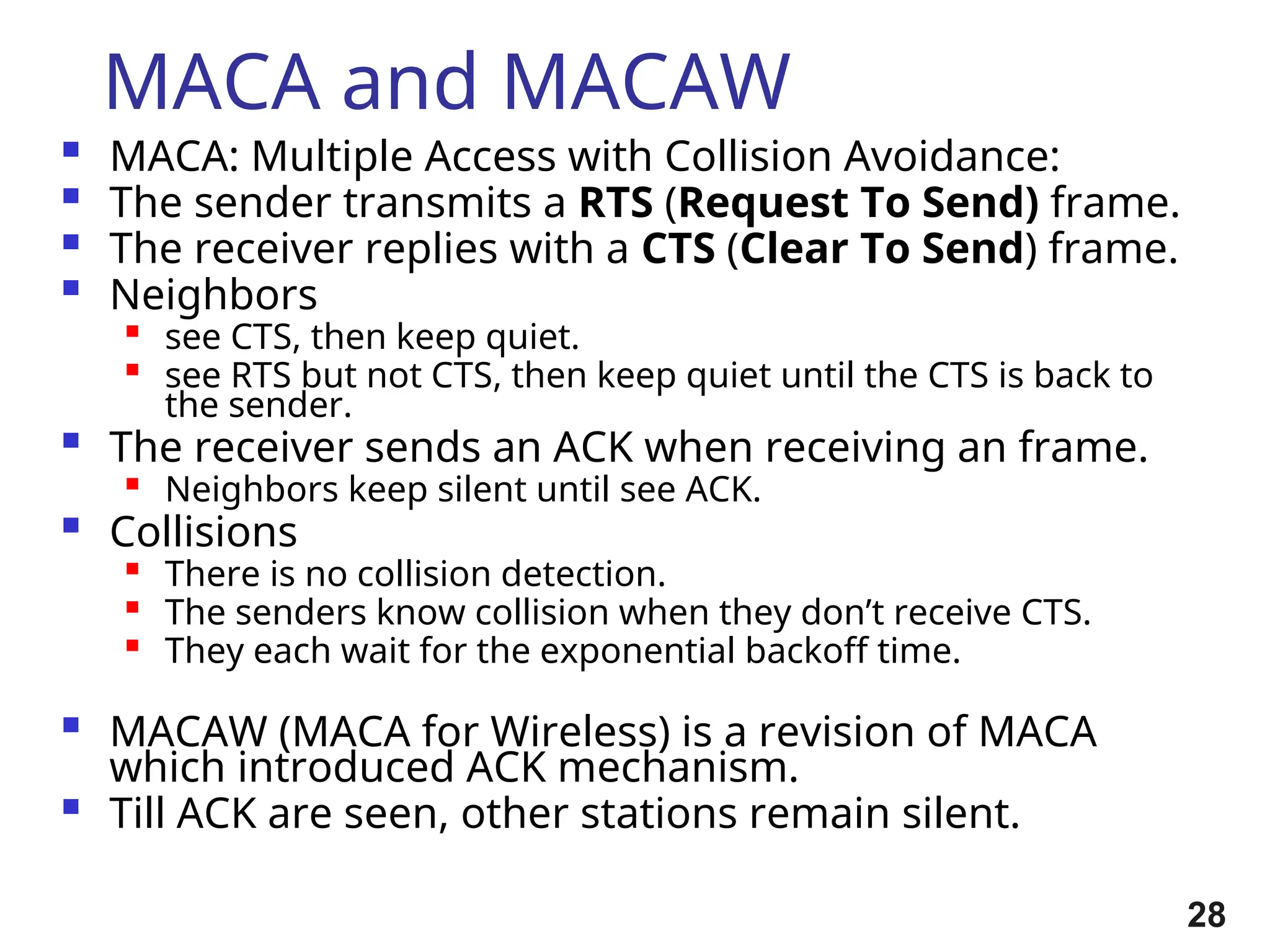
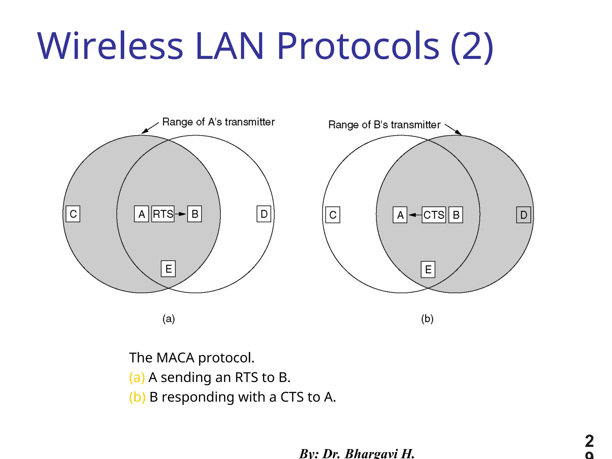
MACA and MACAW
MACA: Multiple Access with Collision Avoidance:
The sender transmits a RTS (Request To Send) frame.
The receiver replies with a CTS (Clear To Send) frame.
Neighbors
see CTS, then keep quiet.
see RTS but not CTS, then keep quiet until the CTS is back to
the sender.
The receiver sends an ACK when receiving an frame.
Neighbors keep silent until see ACK.
Collisions
There is no collision detection.
The senders know collision when they don’t receive CTS.
They each wait for the exponential backoff time.
MACAW (MACA for Wireless) is a revision of MACA
which introduced ACK mechanism.
Till ACK are seen, other stations remain silent.
28
29.
The MACA protocol.
(a)A sending an RTS to B.
(b) B responding with a CTS to A.
Wireless LAN Protocols (2)
By: Dr. Bhargavi H.
2
12.36
In CSMA/CA, theIFS can also be used to
define the priority of a station or a
frame.
Note
37.
12.37
In CSMA/CA, ifthe station finds the
channel busy, it does not restart the
timer of the contention window;
it stops the timer and restarts it when
the channel becomes idle.
Note
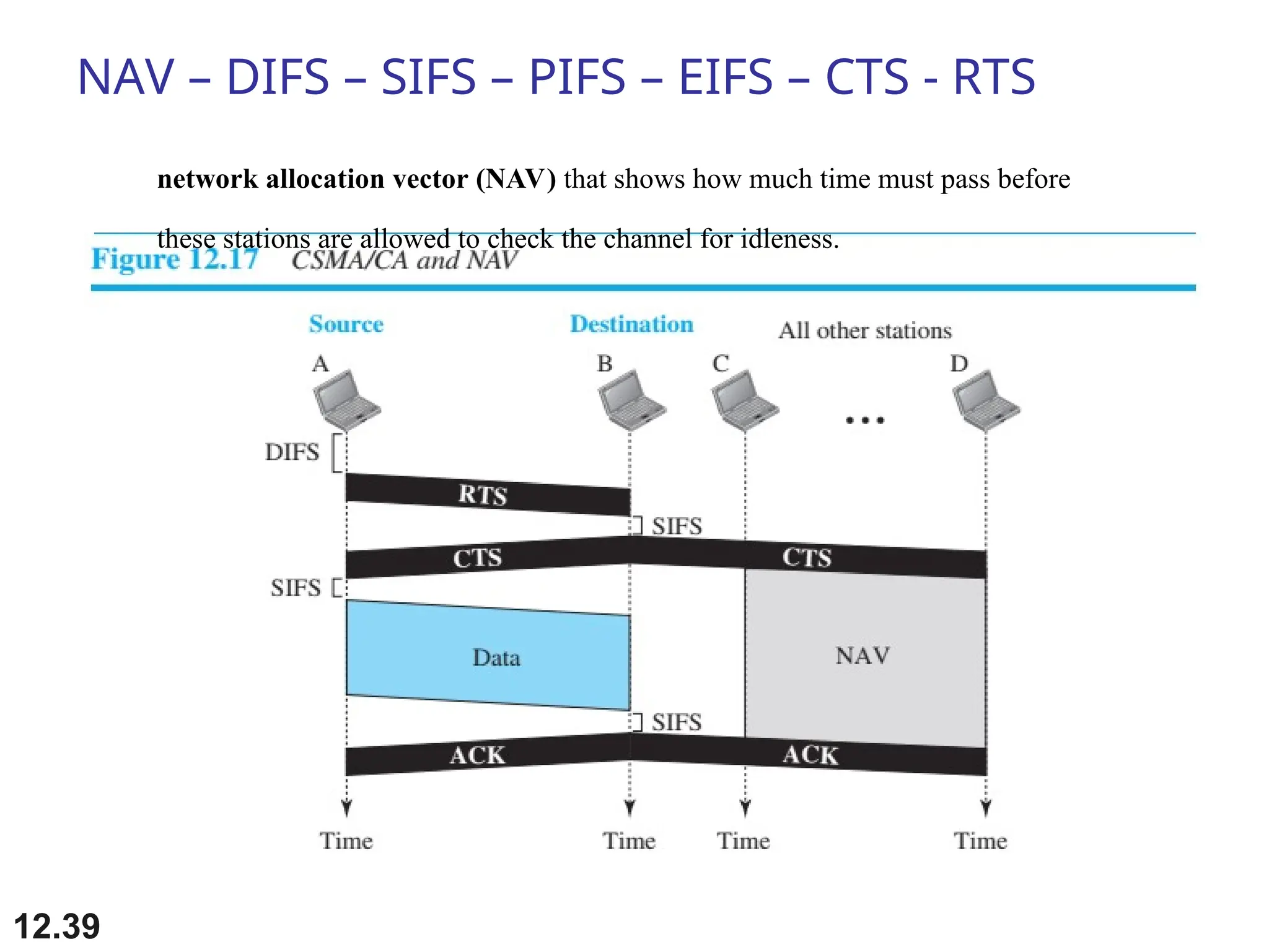
NAV – DIFS– SIFS – PIFS – EIFS – CTS - RTS
12.39
network allocation vector (NAV) that shows how much time must pass before
these stations are allowed to check the channel for idleness.
40.
12.40
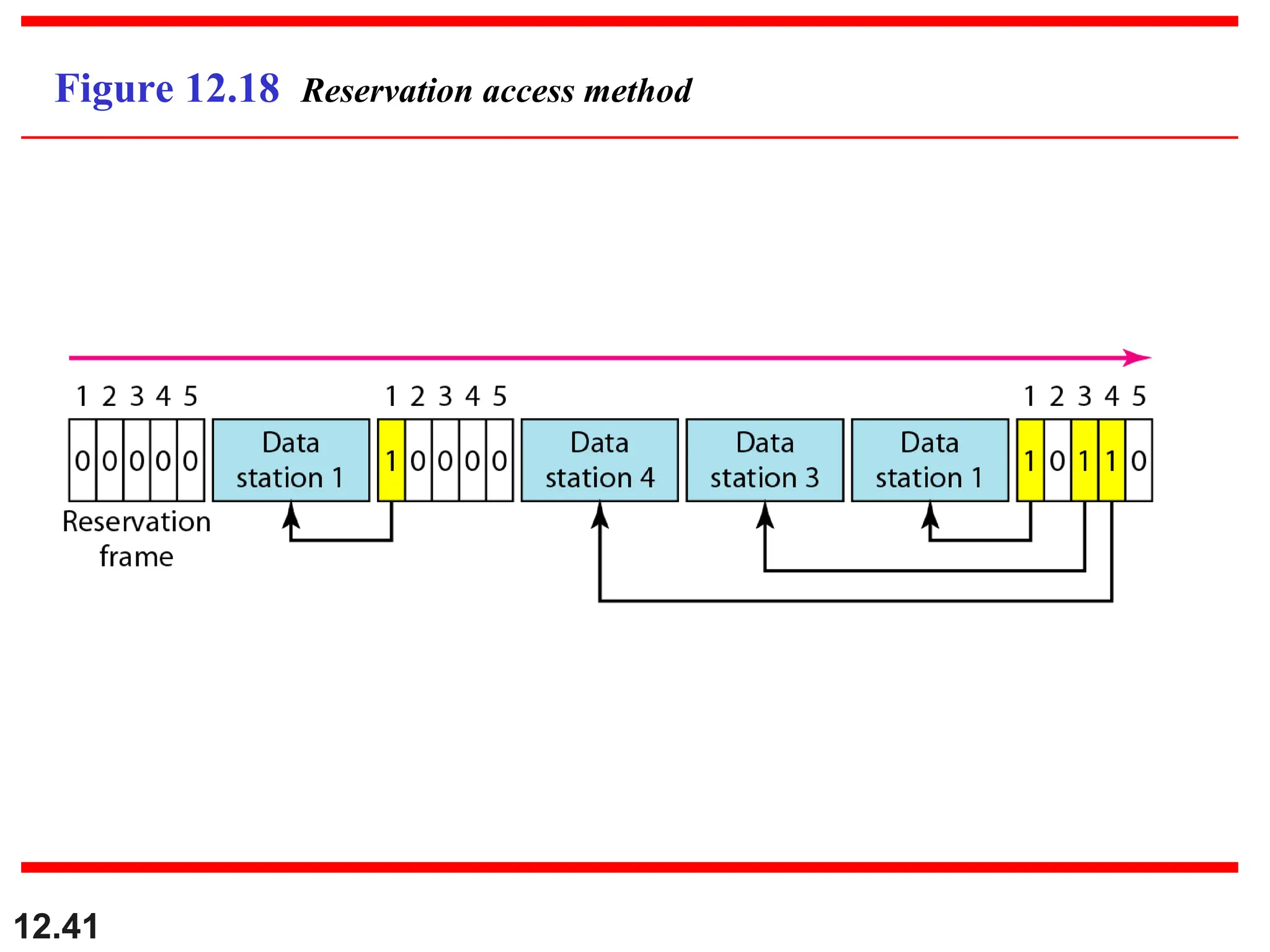
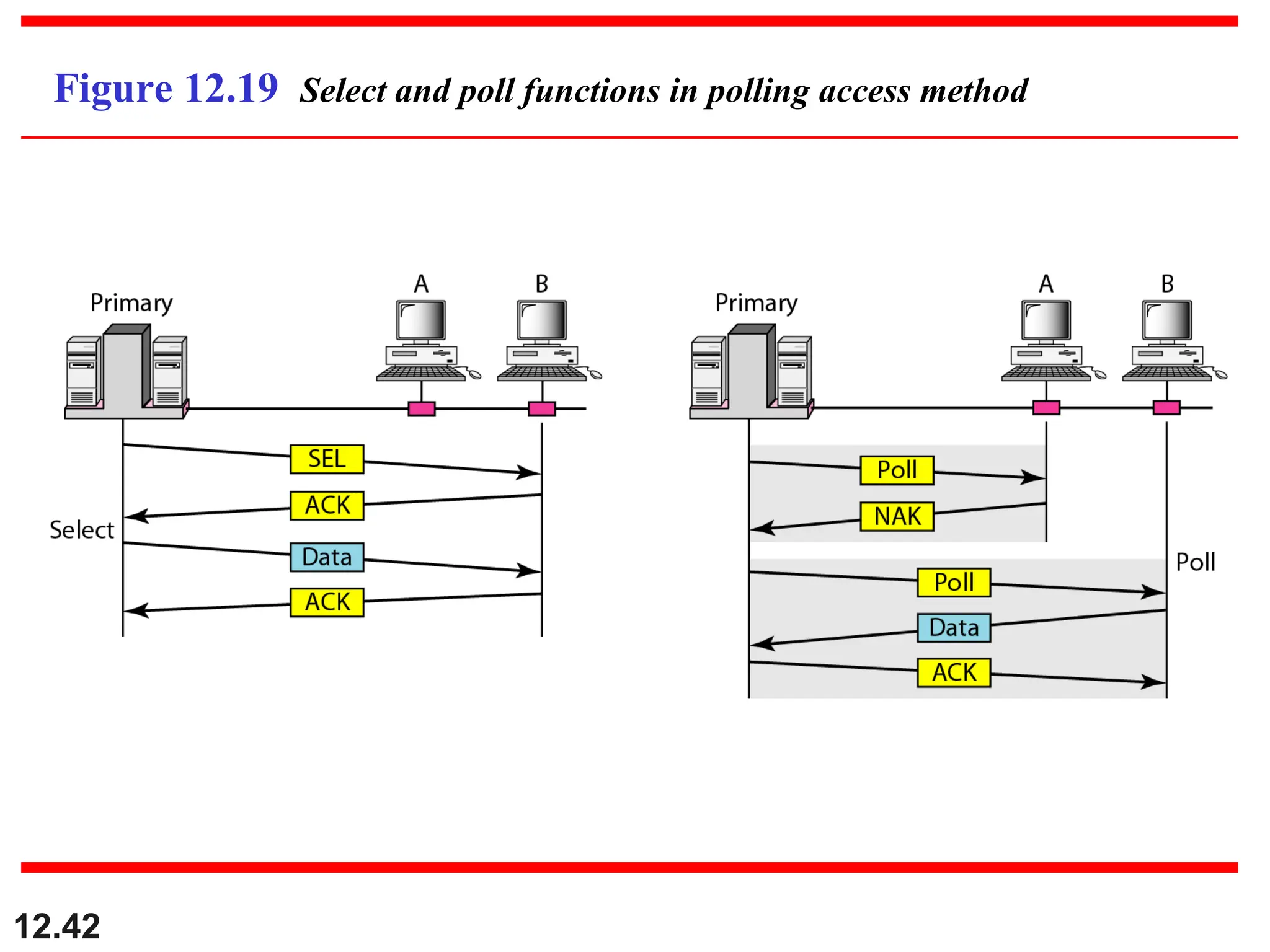
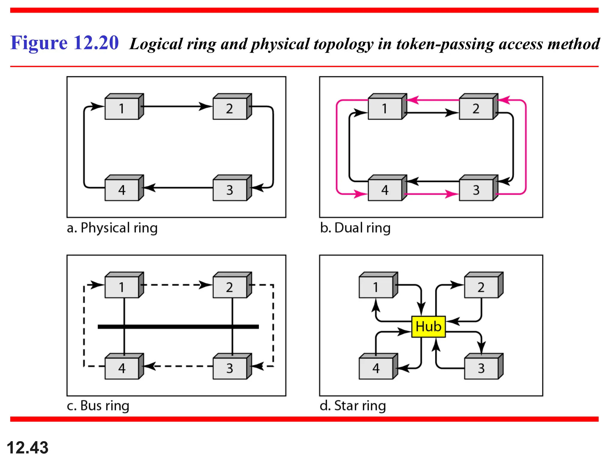
12-2 CONTROLLED ACCESS
12-2CONTROLLED ACCESS
In
In controlled access
controlled access, the stations consult one another
, the stations consult one another
to find which station has the right to send. A station
to find which station has the right to send. A station
cannot send unless it has been authorized by other
cannot send unless it has been authorized by other
stations. We discuss three popular controlled-access
stations. We discuss three popular controlled-access
methods.
methods.
Reservation
Polling
Token Passing
Topics discussed in this section:
Topics discussed in this section:
12.44
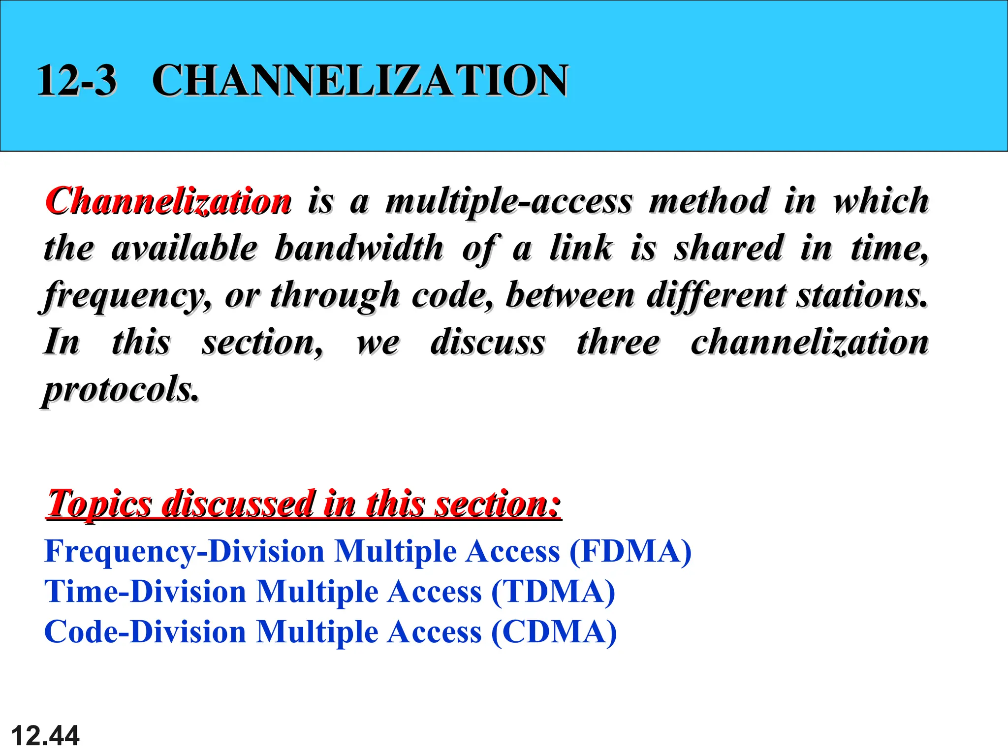
12-3 CHANNELIZATION
12-3 CHANNELIZATION
Channelization
Channelizationis a multiple-access method in which
is a multiple-access method in which
the available bandwidth of a link is shared in time,
the available bandwidth of a link is shared in time,
frequency, or through code, between different stations.
frequency, or through code, between different stations.
In this section, we discuss three channelization
In this section, we discuss three channelization
protocols.
protocols.
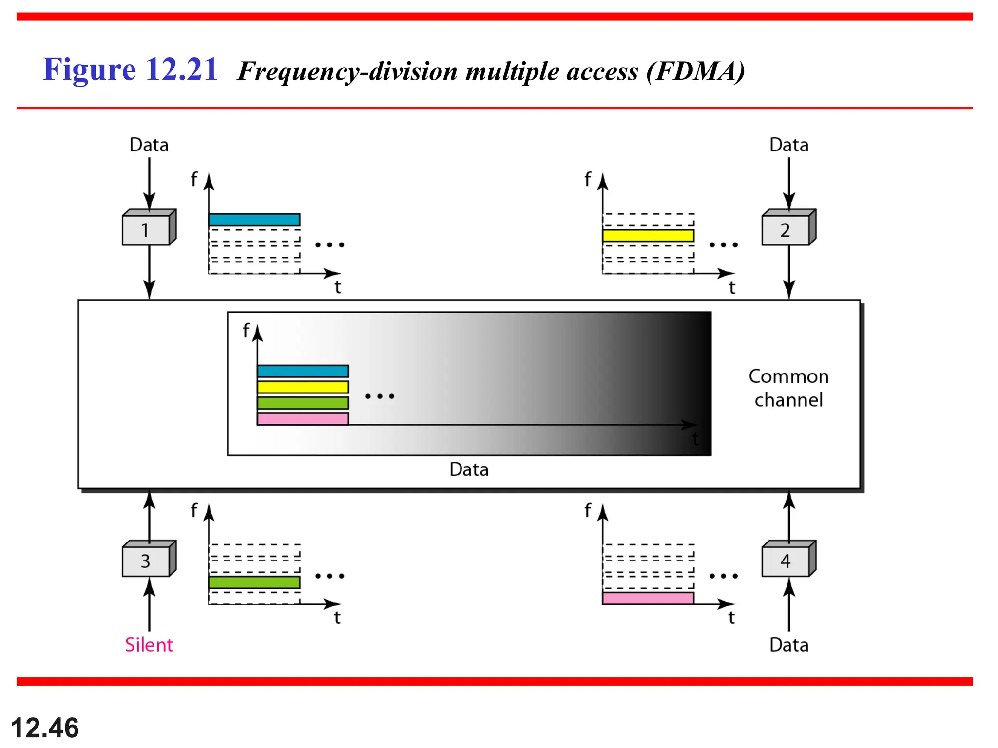
Frequency-Division Multiple Access (FDMA)
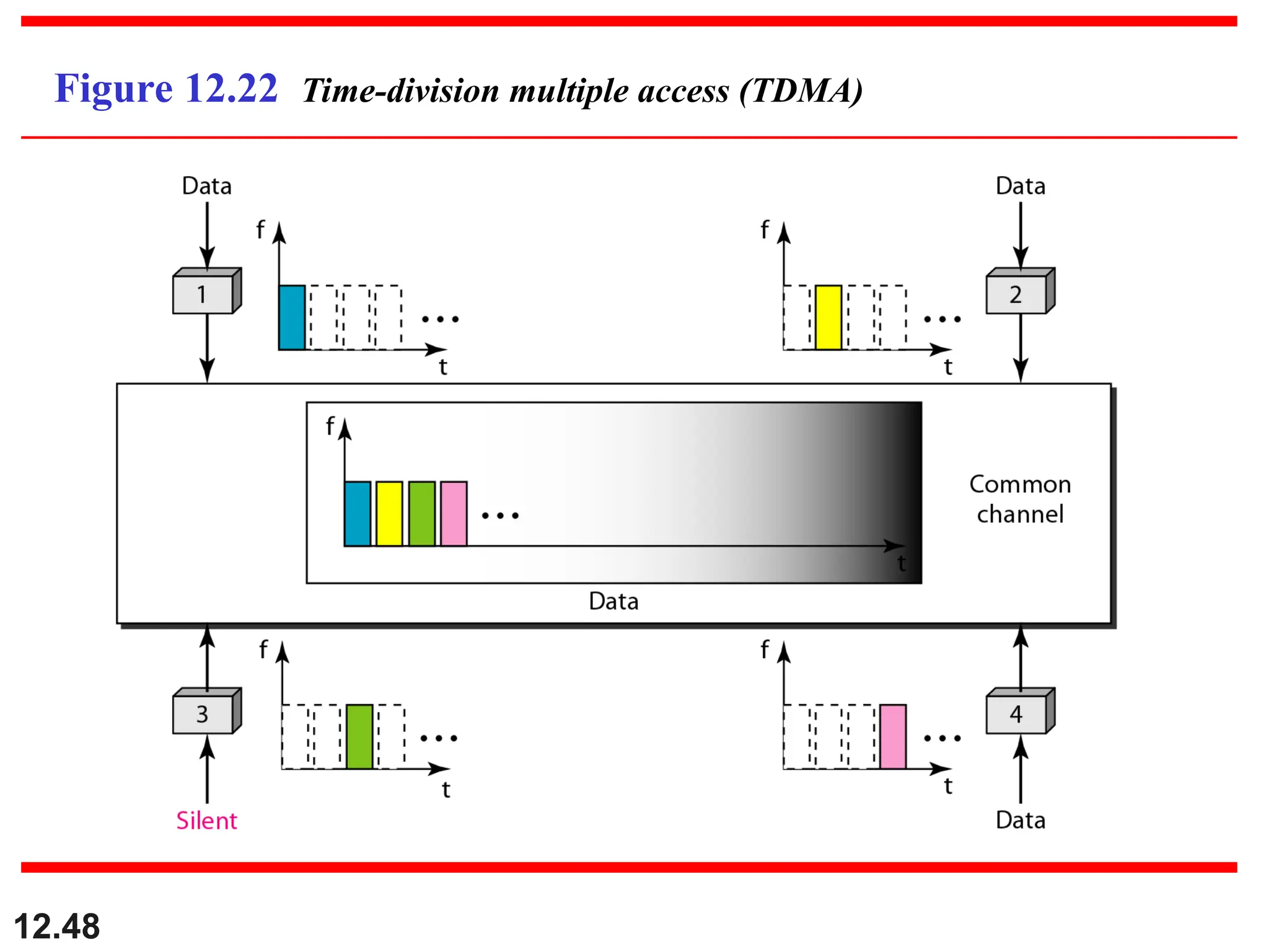
Time-Division Multiple Access (TDMA)
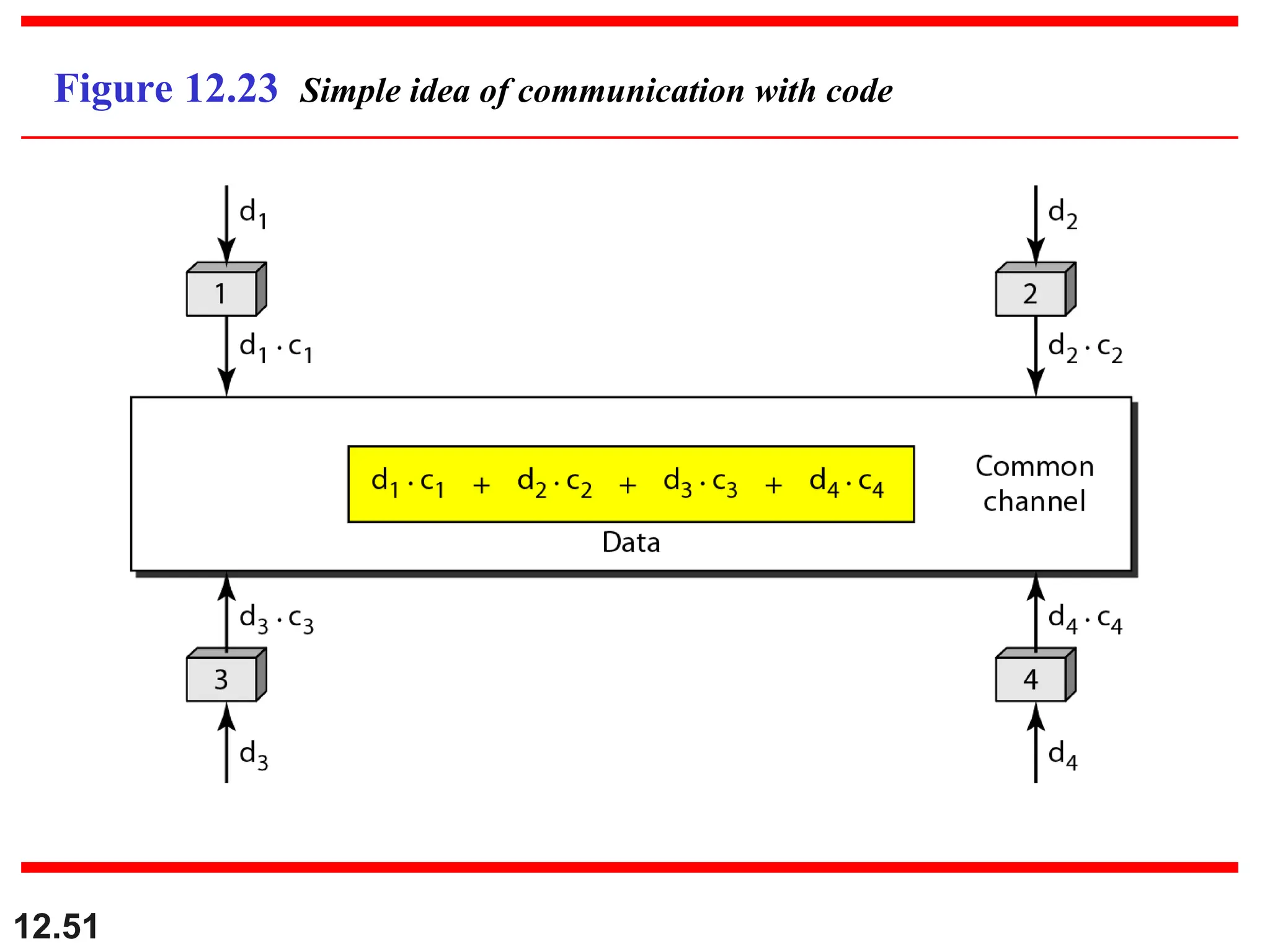
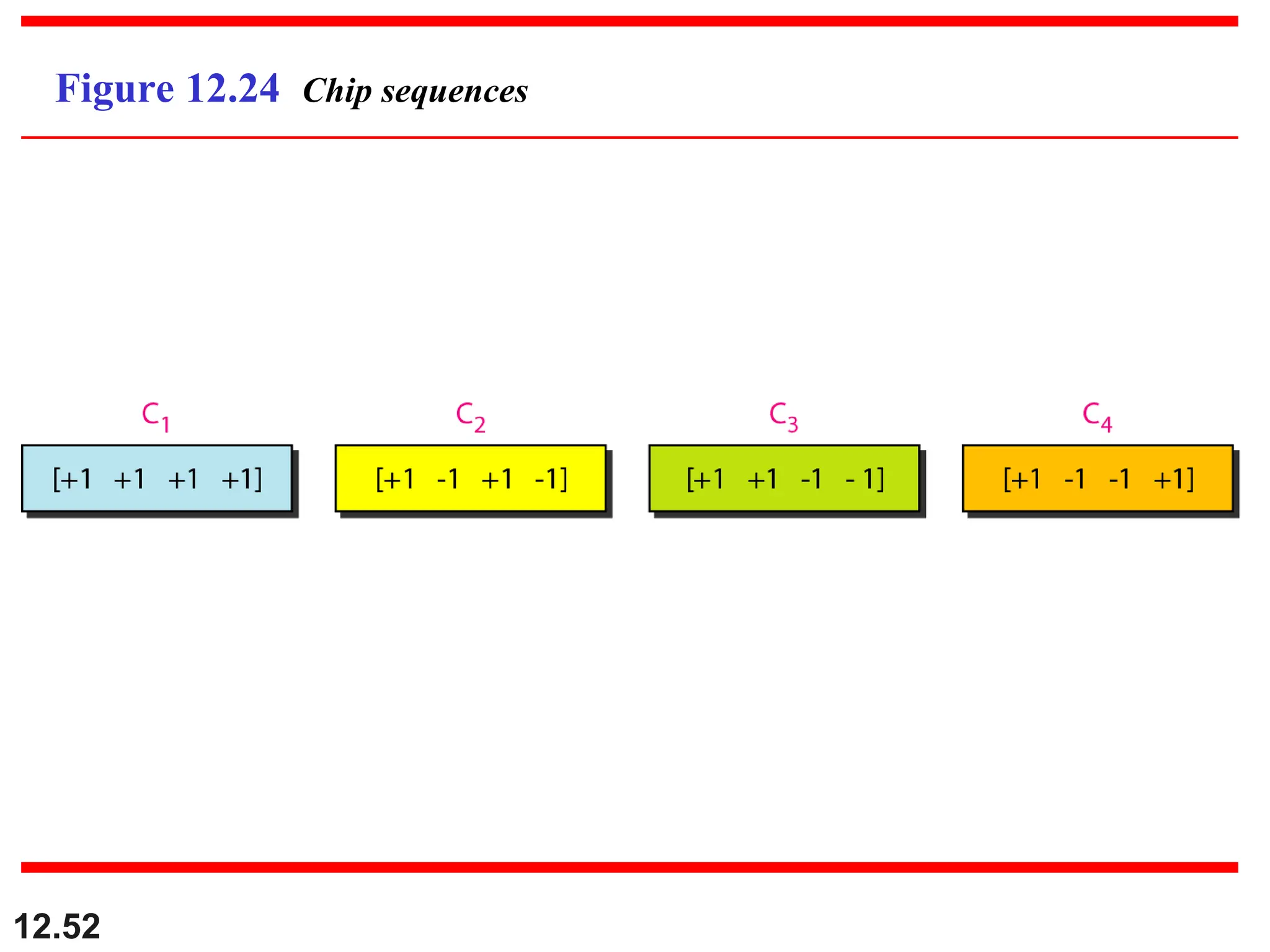
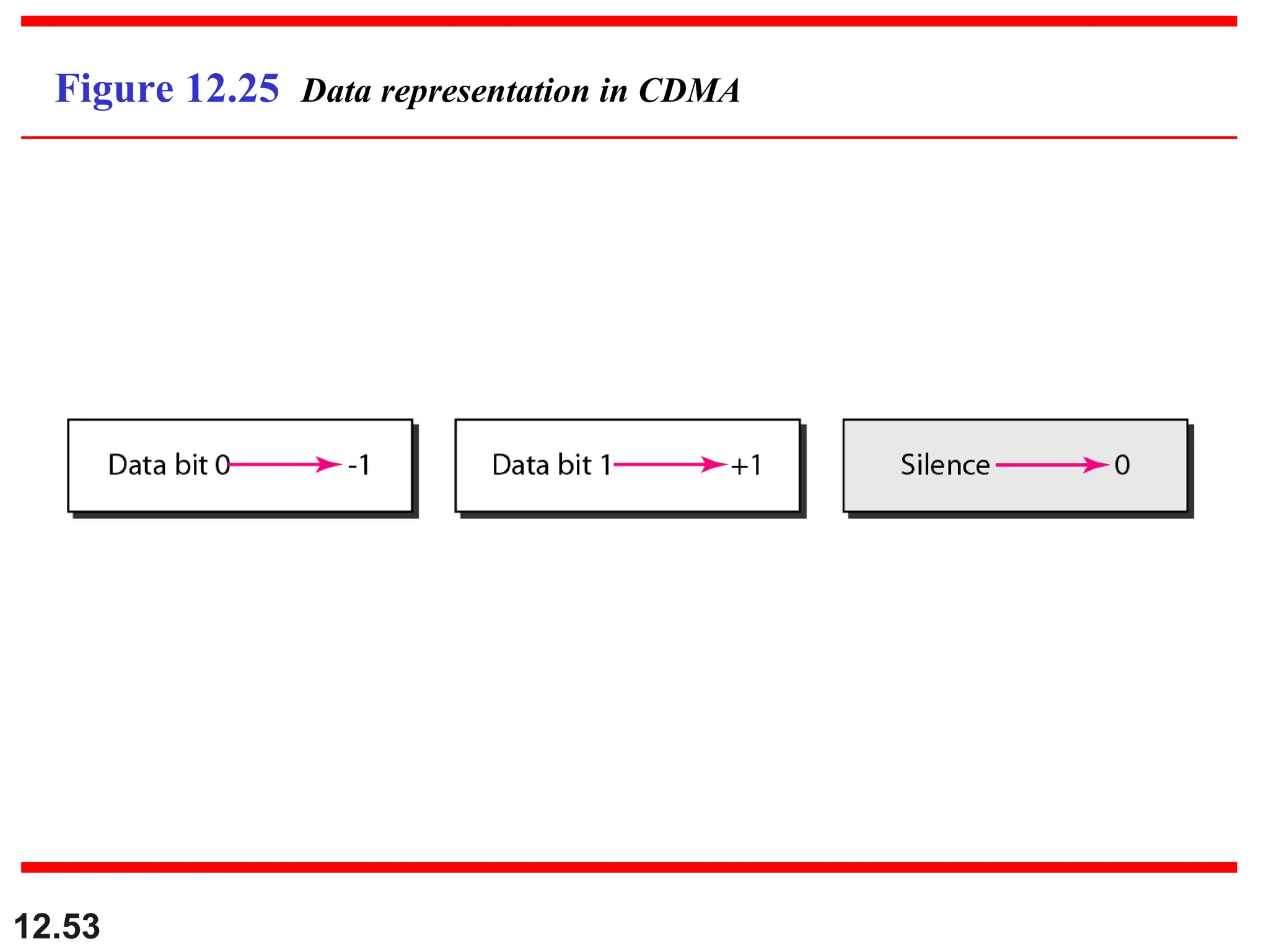
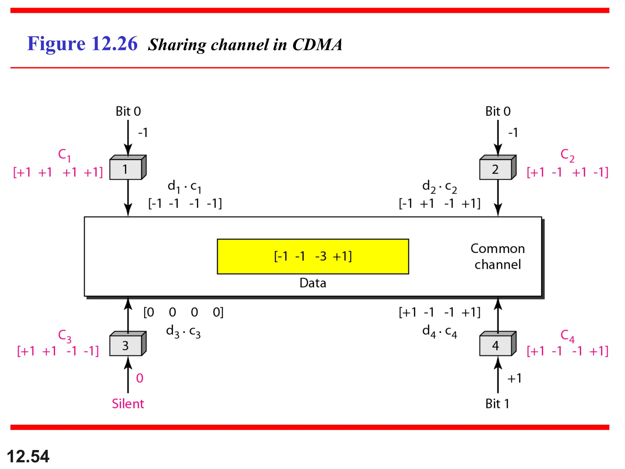
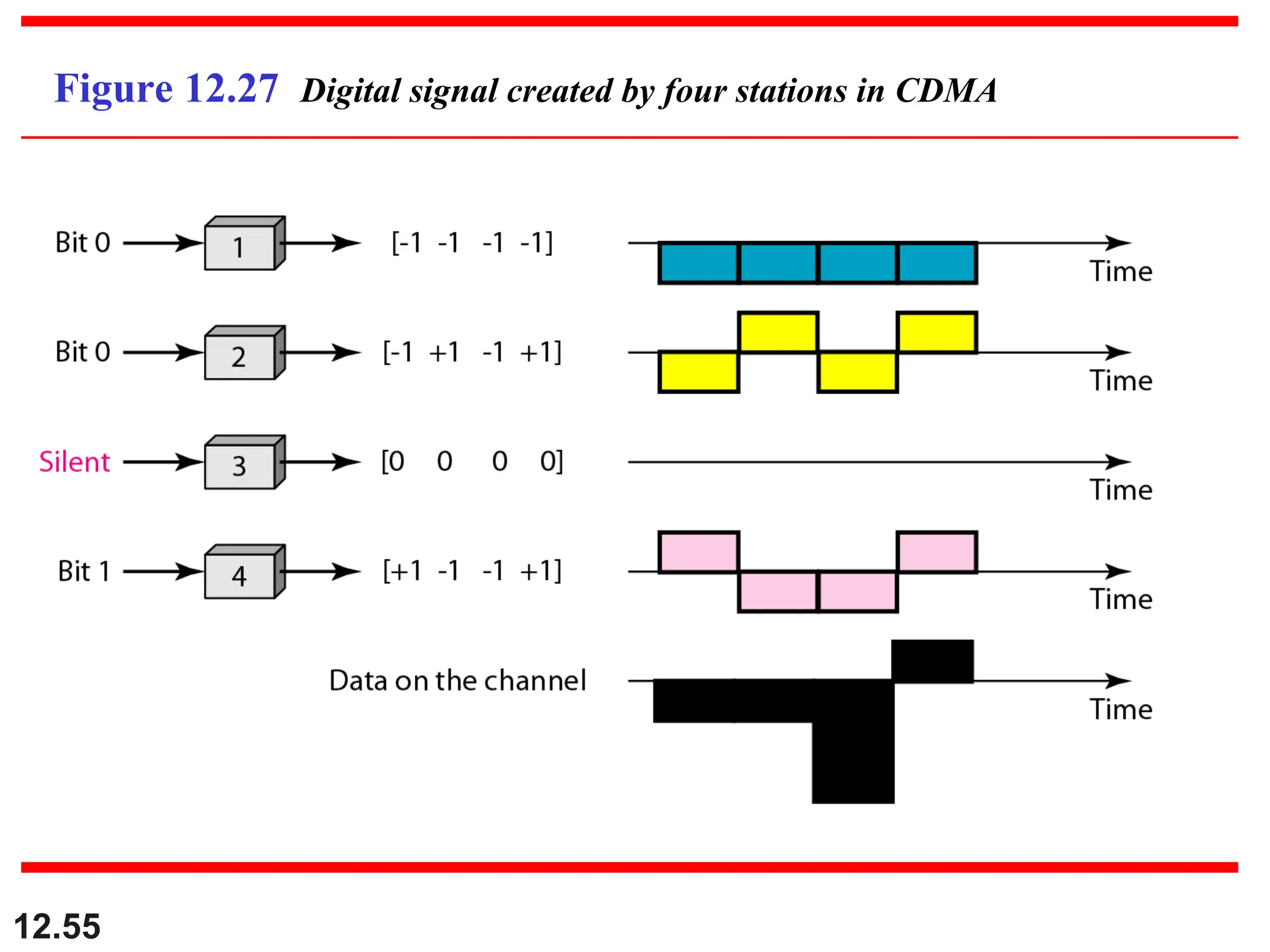
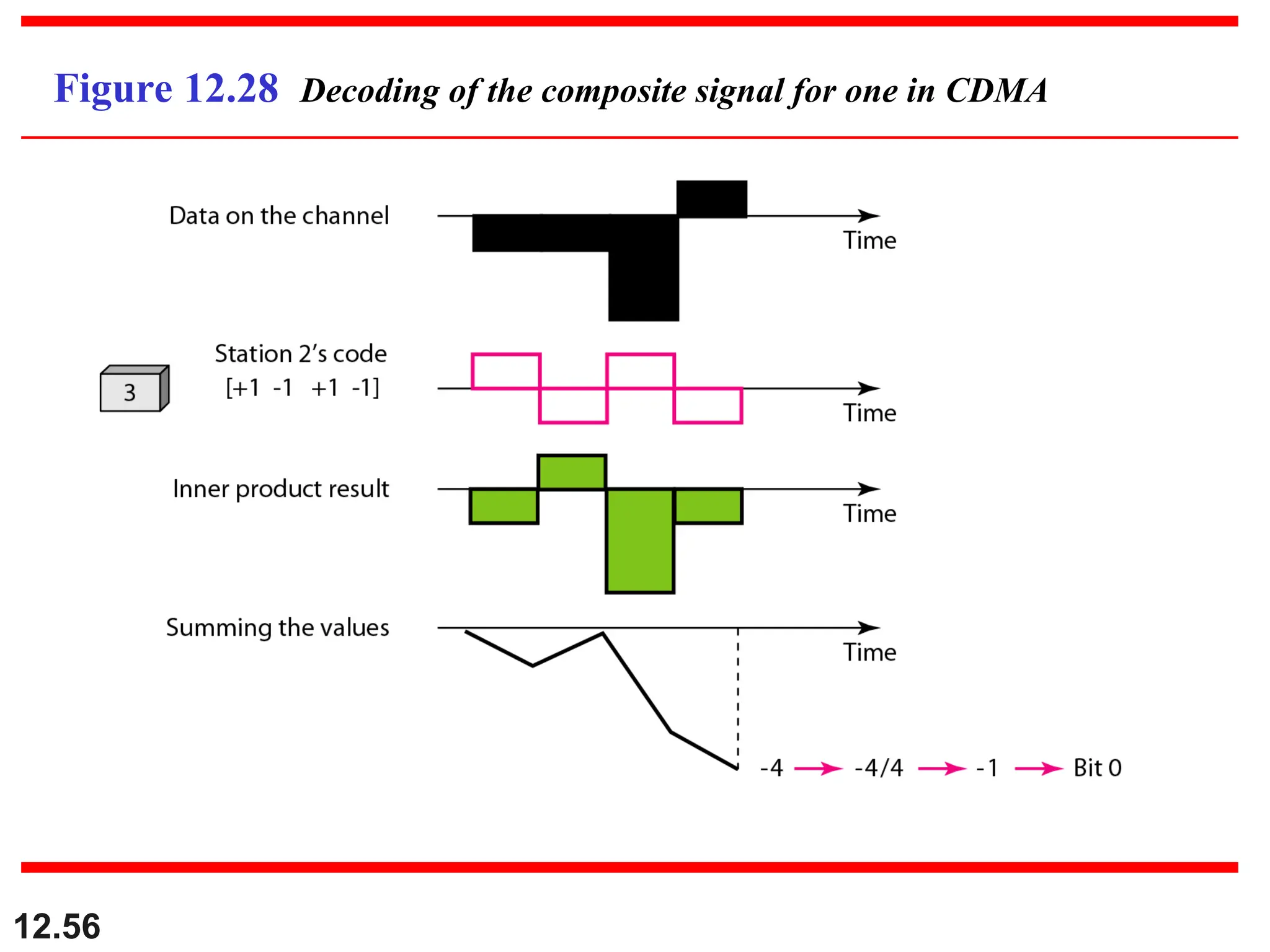
Code-Division Multiple Access (CDMA)
Topics discussed in this section:
Topics discussed in this section:
45.
12.45
We see theapplication of all these
methods in Chapter 16 when
we discuss cellular phone systems.
Note