Multiple Access
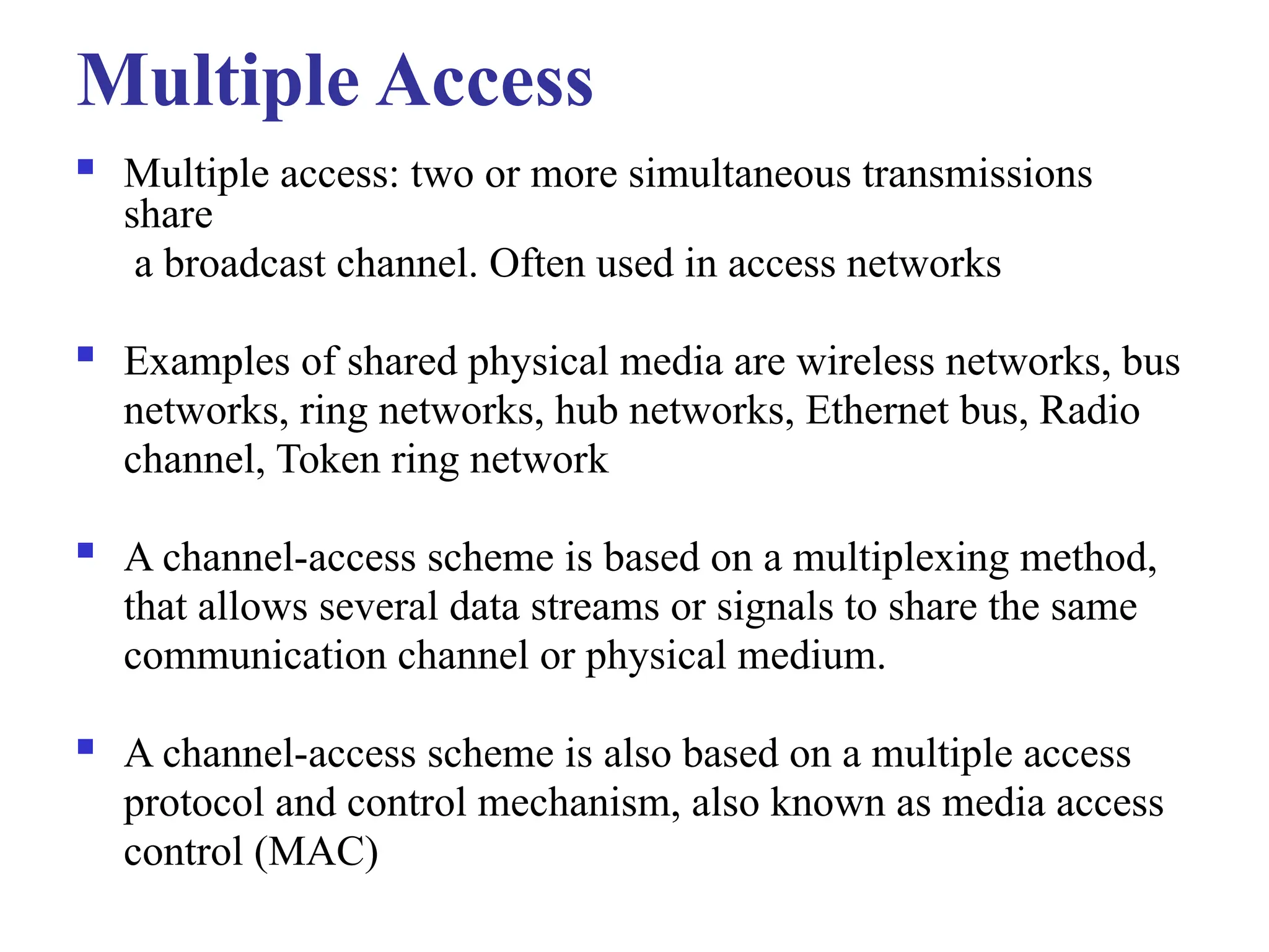
Multipleaccess: two or more simultaneous transmissions
share
a broadcast channel. Often used in access networks
Examples of shared physical media are wireless networks, bus
networks, ring networks, hub networks, Ethernet bus, Radio
channel, Token ring network
A channel-access scheme is based on a multiplexing method,
that allows several data streams or signals to share the same
communication channel or physical medium.
A channel-access scheme is also based on a multiple access
protocol and control mechanism, also known as media access
control (MAC)
4.
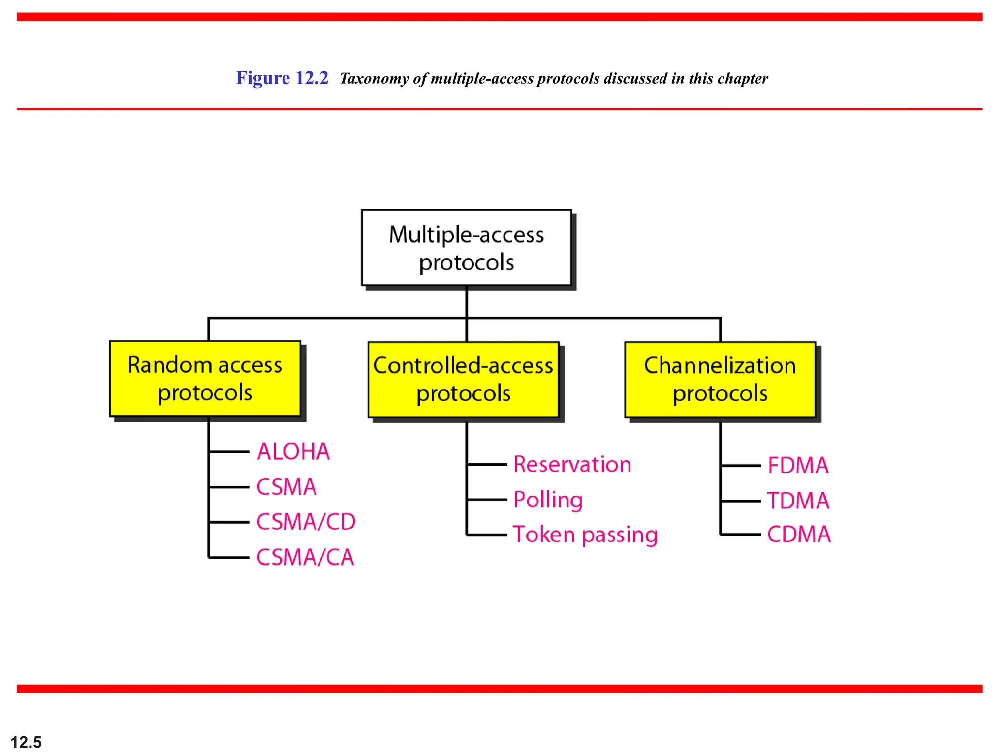
Multiple Access Protocols
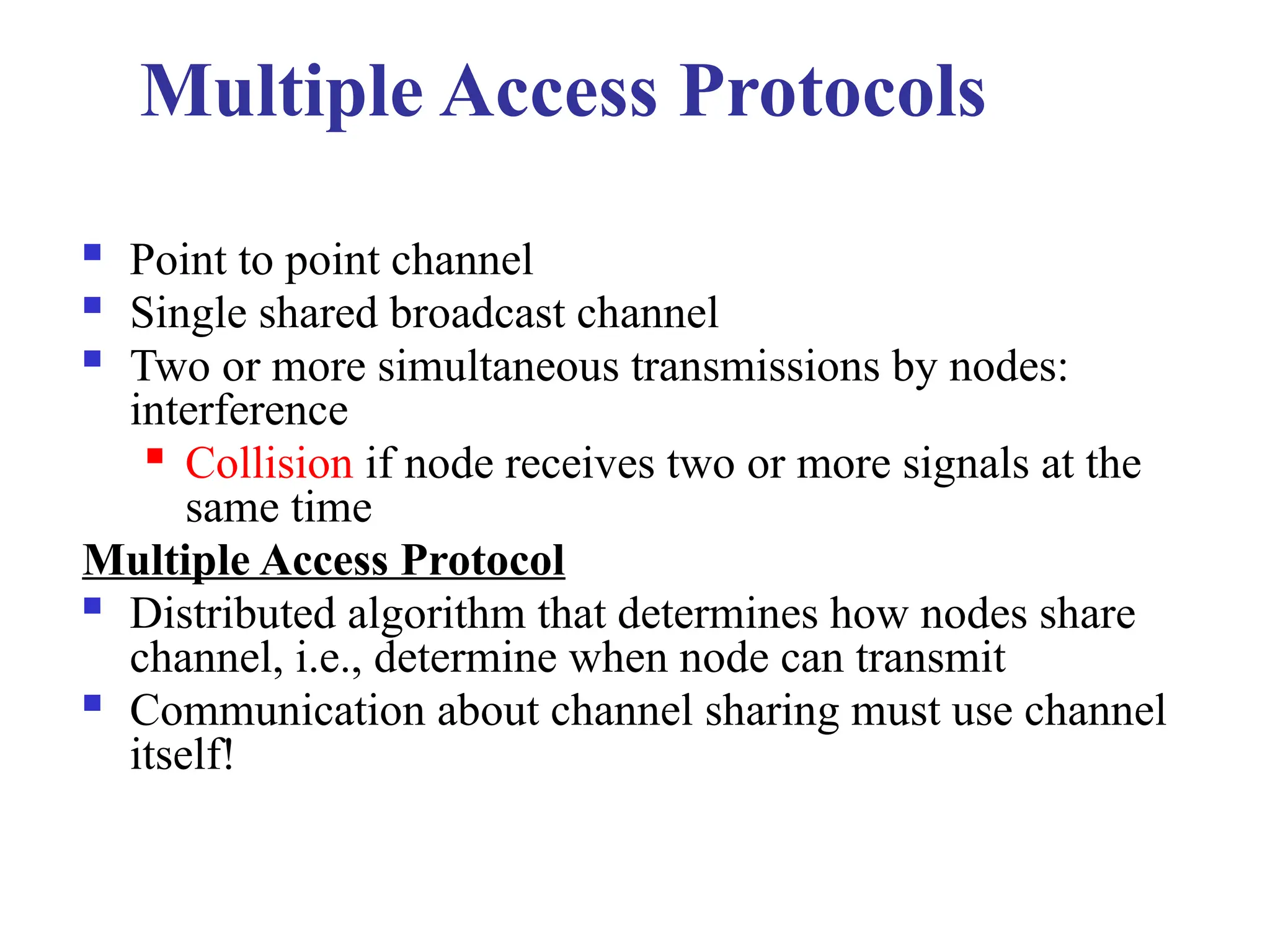
Point to point channel
Single shared broadcast channel
Two or more simultaneous transmissions by nodes:
interference
Collision if node receives two or more signals at the
same time
Multiple Access Protocol
Distributed algorithm that determines how nodes share
channel, i.e., determine when node can transmit
Communication about channel sharing must use channel
itself!
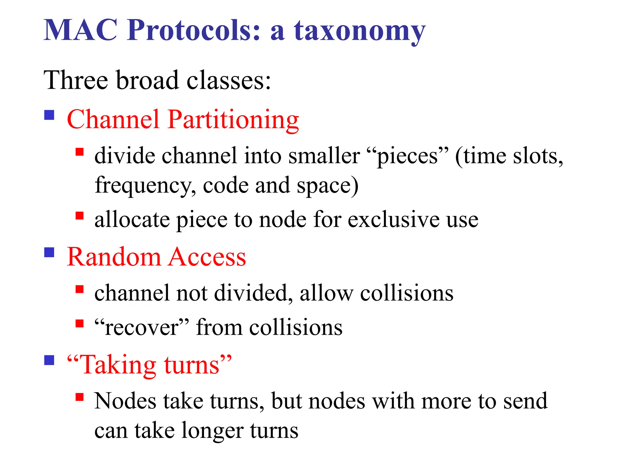
MAC Protocols: ataxonomy
Three broad classes:
Channel Partitioning
divide channel into smaller “pieces” (time slots,
frequency, code and space)
allocate piece to node for exclusive use
Random Access
channel not divided, allow collisions
“recover” from collisions
“Taking turns”
Nodes take turns, but nodes with more to send
can take longer turns
7.
12.7
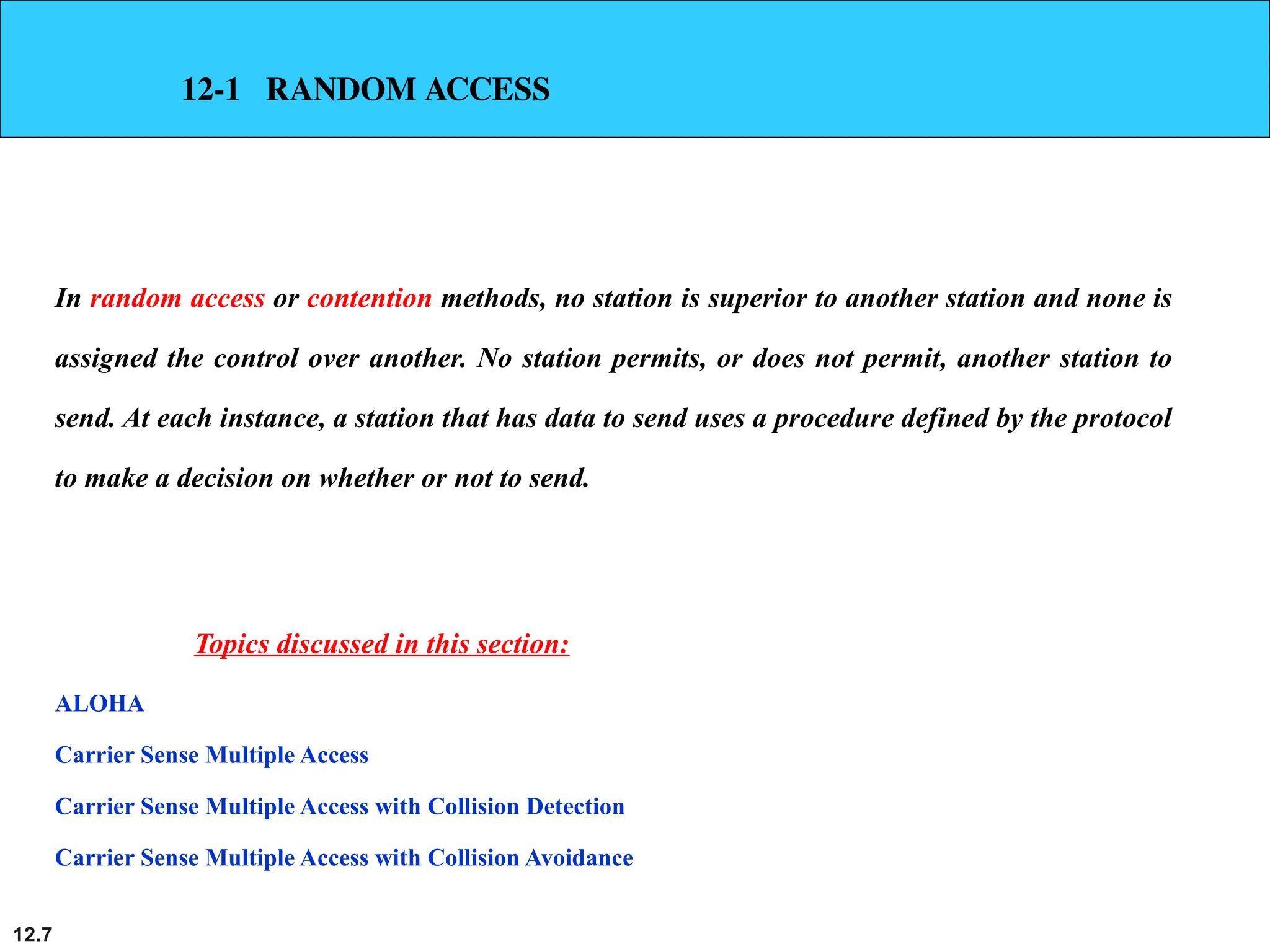
12-1 RANDOM ACCESS
Inrandom access or contention methods, no station is superior to another station and none is
assigned the control over another. No station permits, or does not permit, another station to
send. At each instance, a station that has data to send uses a procedure defined by the protocol
to make a decision on whether or not to send.
ALOHA
Carrier Sense Multiple Access
Carrier Sense Multiple Access with Collision Detection
Carrier Sense Multiple Access with Collision Avoidance
Topics discussed in this section:
8.
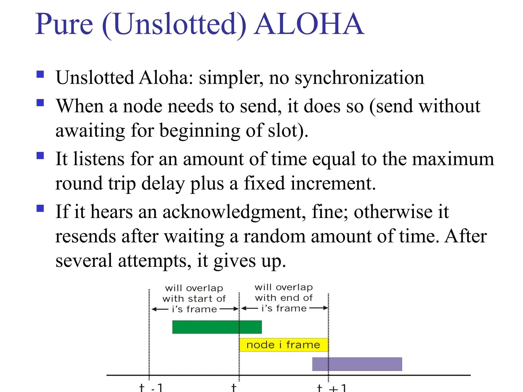
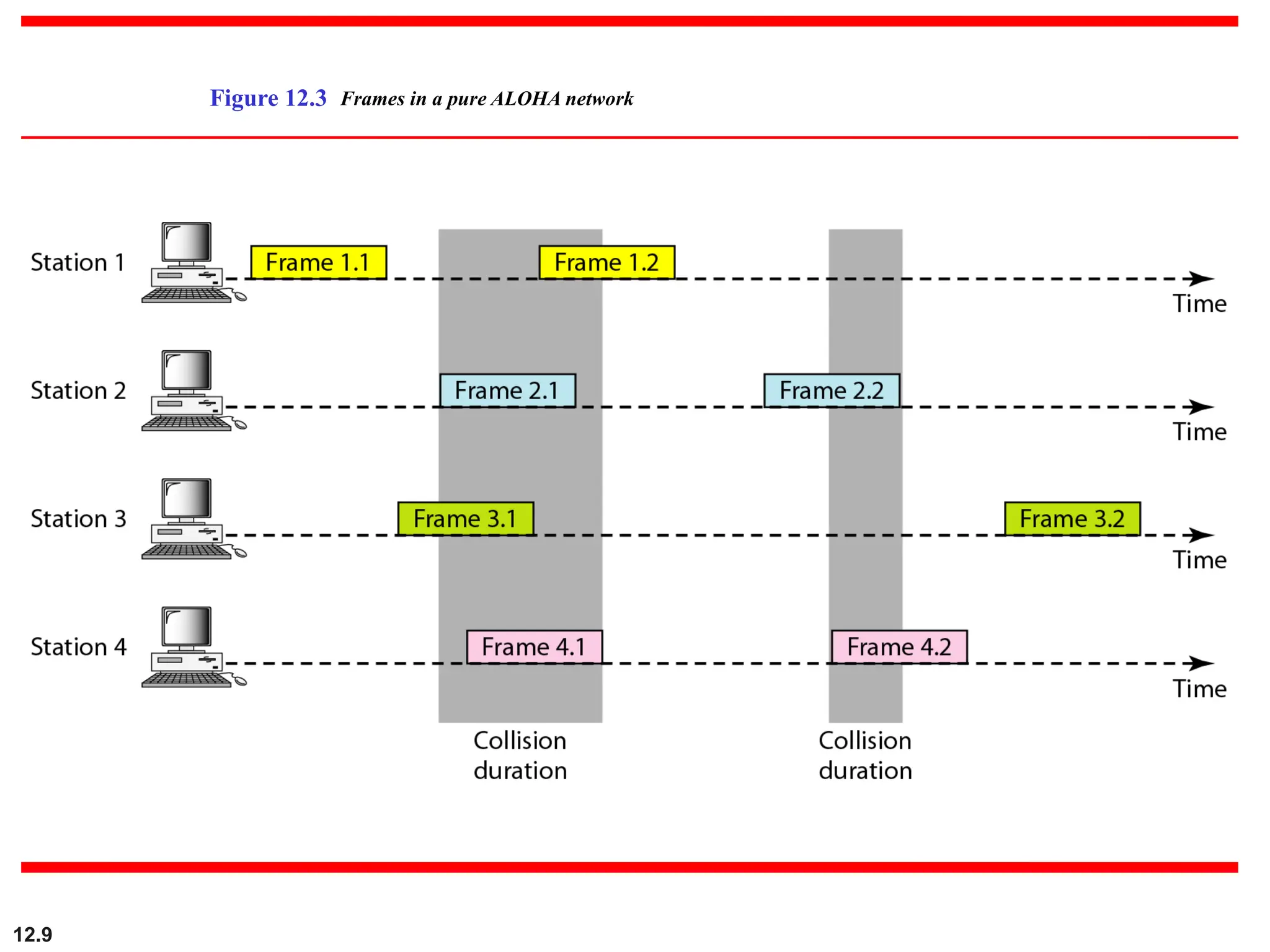
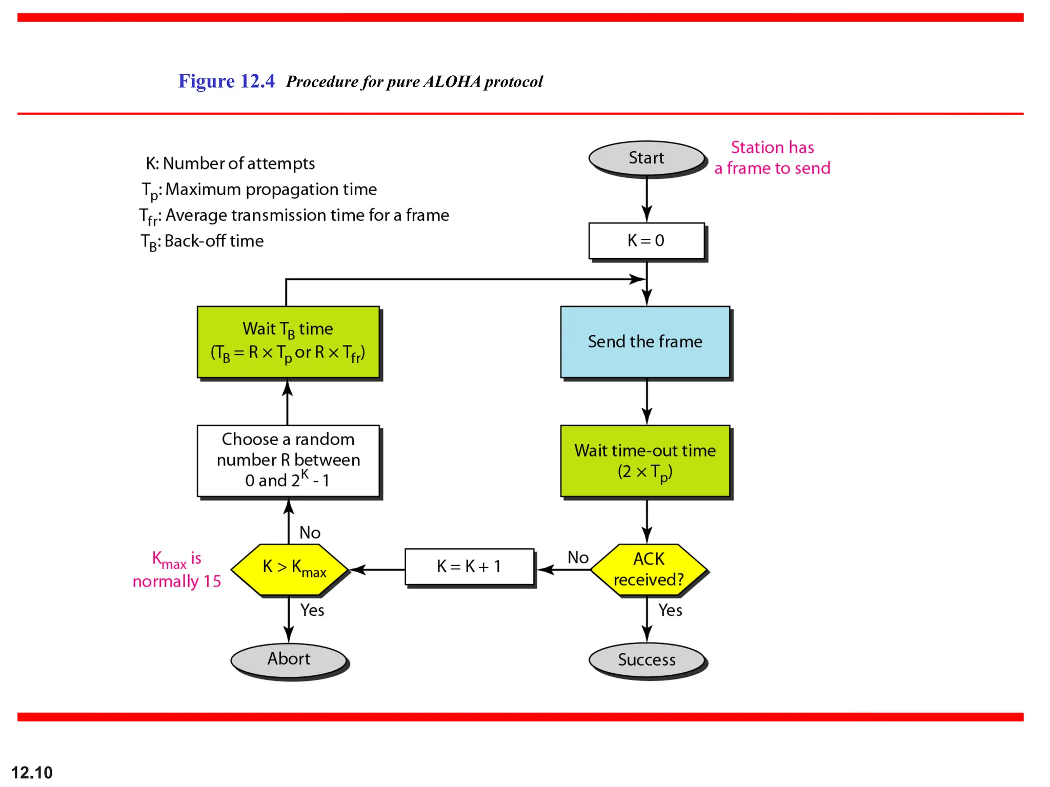
Pure (Unslotted) ALOHA
Unslotted Aloha: simpler, no synchronization
When a node needs to send, it does so (send without
awaiting for beginning of slot).
It listens for an amount of time equal to the maximum
round trip delay plus a fixed increment.
If it hears an acknowledgment, fine; otherwise it
resends after waiting a random amount of time. After
several attempts, it gives up.
12.11
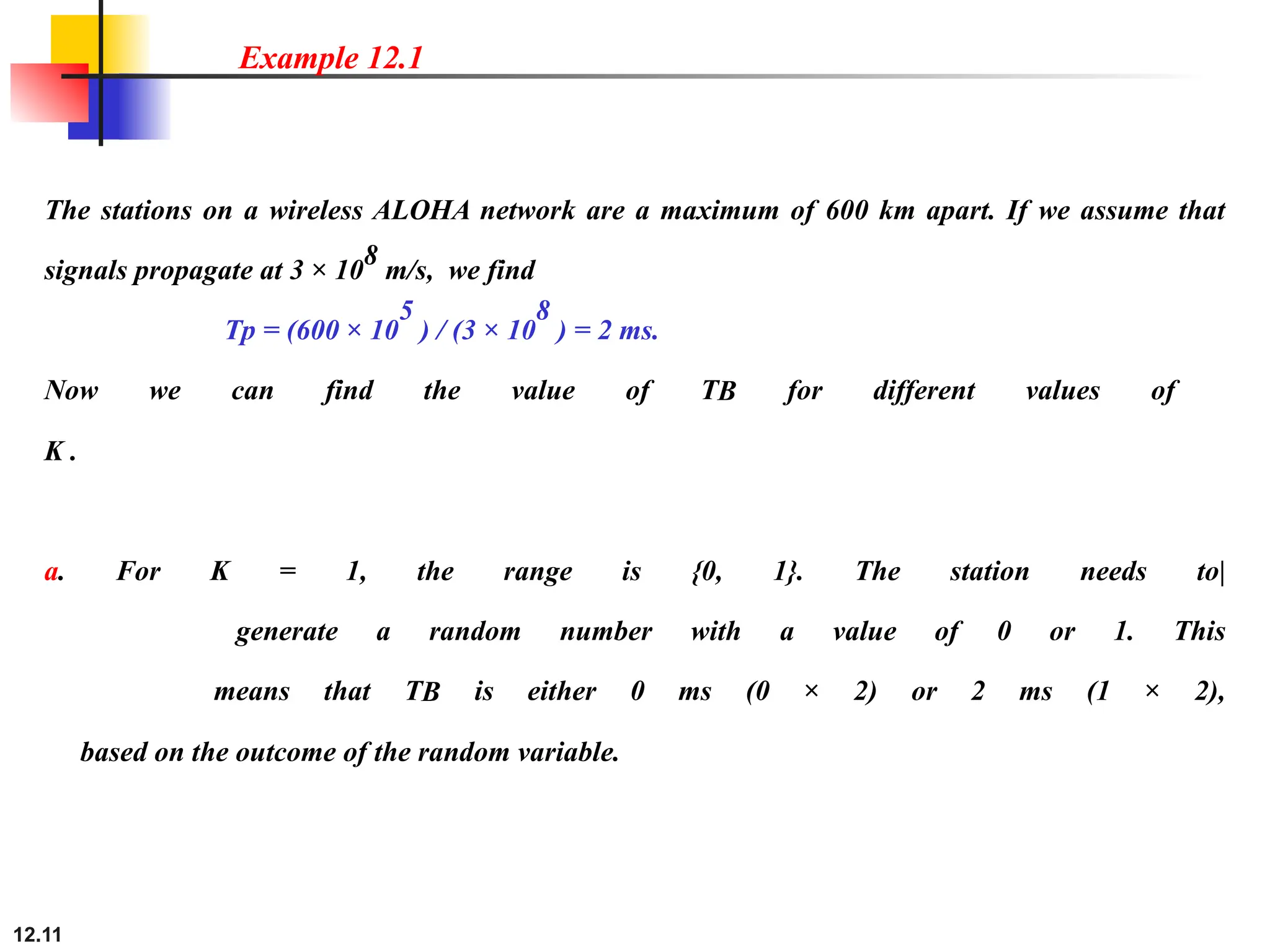
The stations ona wireless ALOHA network are a maximum of 600 km apart. If we assume that
signals propagate at 3 × 10
8
m/s, we find
Tp = (600 × 10
5
) / (3 × 10
8
) = 2 ms.
Now we can find the value of TB for different values of
K .
a. For K = 1, the range is {0, 1}. The station needs to|
generate a random number with a value of 0 or 1. This
means that TB is either 0 ms (0 × 2) or 2 ms (1 × 2),
based on the outcome of the random variable.
Example 12.1
12.
12.12
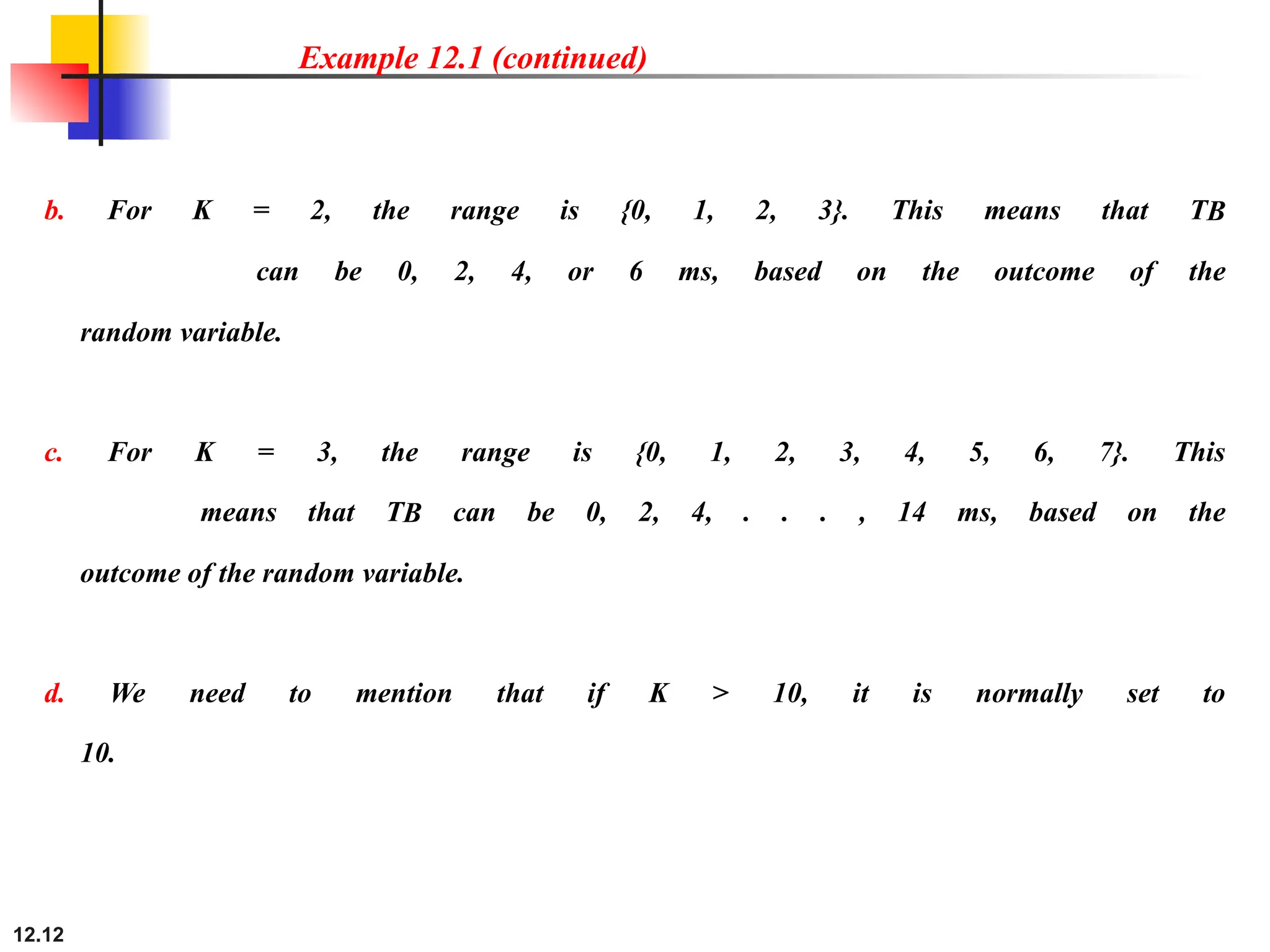
b. For K= 2, the range is {0, 1, 2, 3}. This means that TB
can be 0, 2, 4, or 6 ms, based on the outcome of the
random variable.
c. For K = 3, the range is {0, 1, 2, 3, 4, 5, 6, 7}. This
means that TB can be 0, 2, 4, . . . , 14 ms, based on the
outcome of the random variable.
d. We need to mention that if K > 10, it is normally set to
10.
Example 12.1 (continued)
12.14
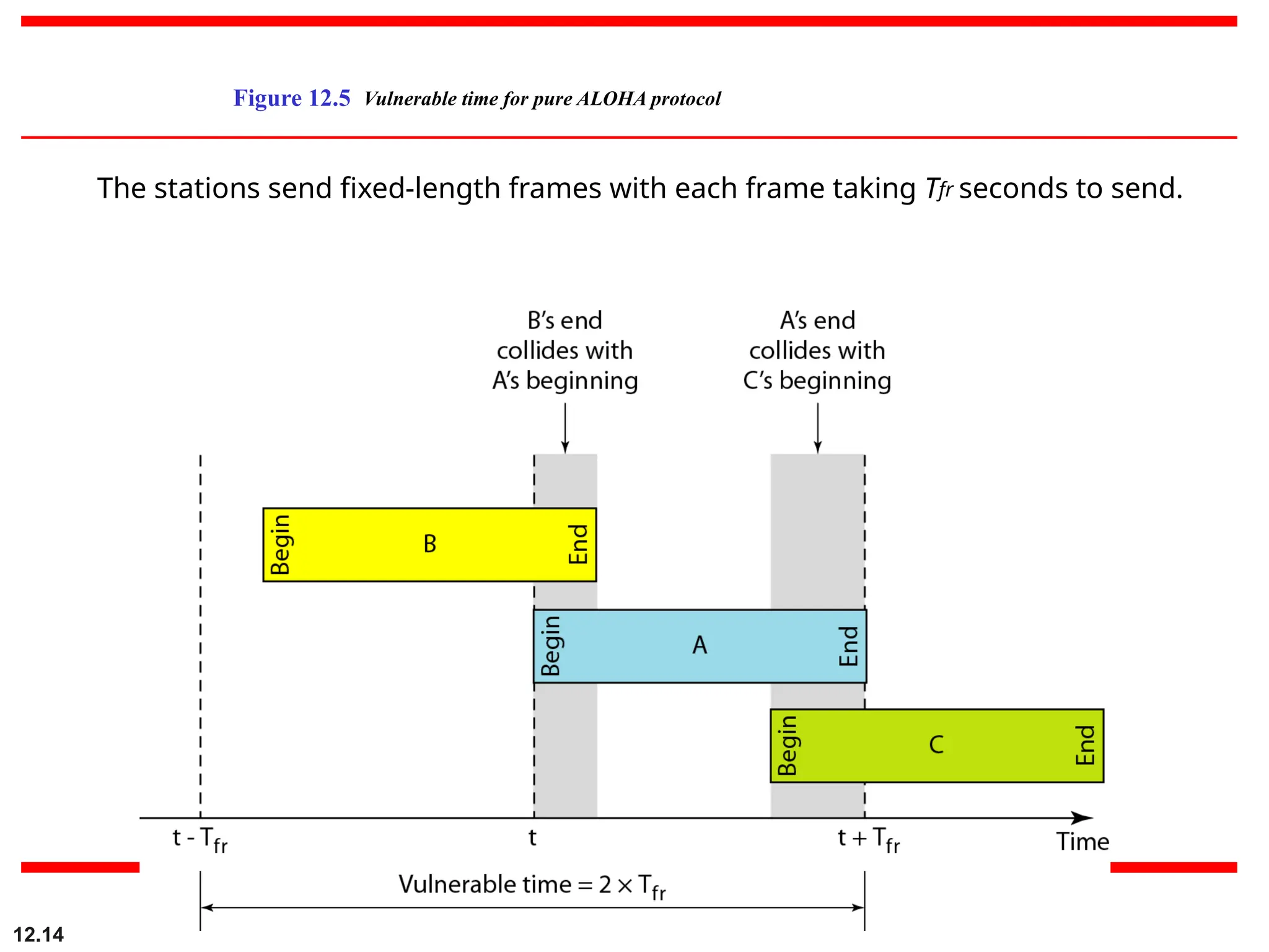
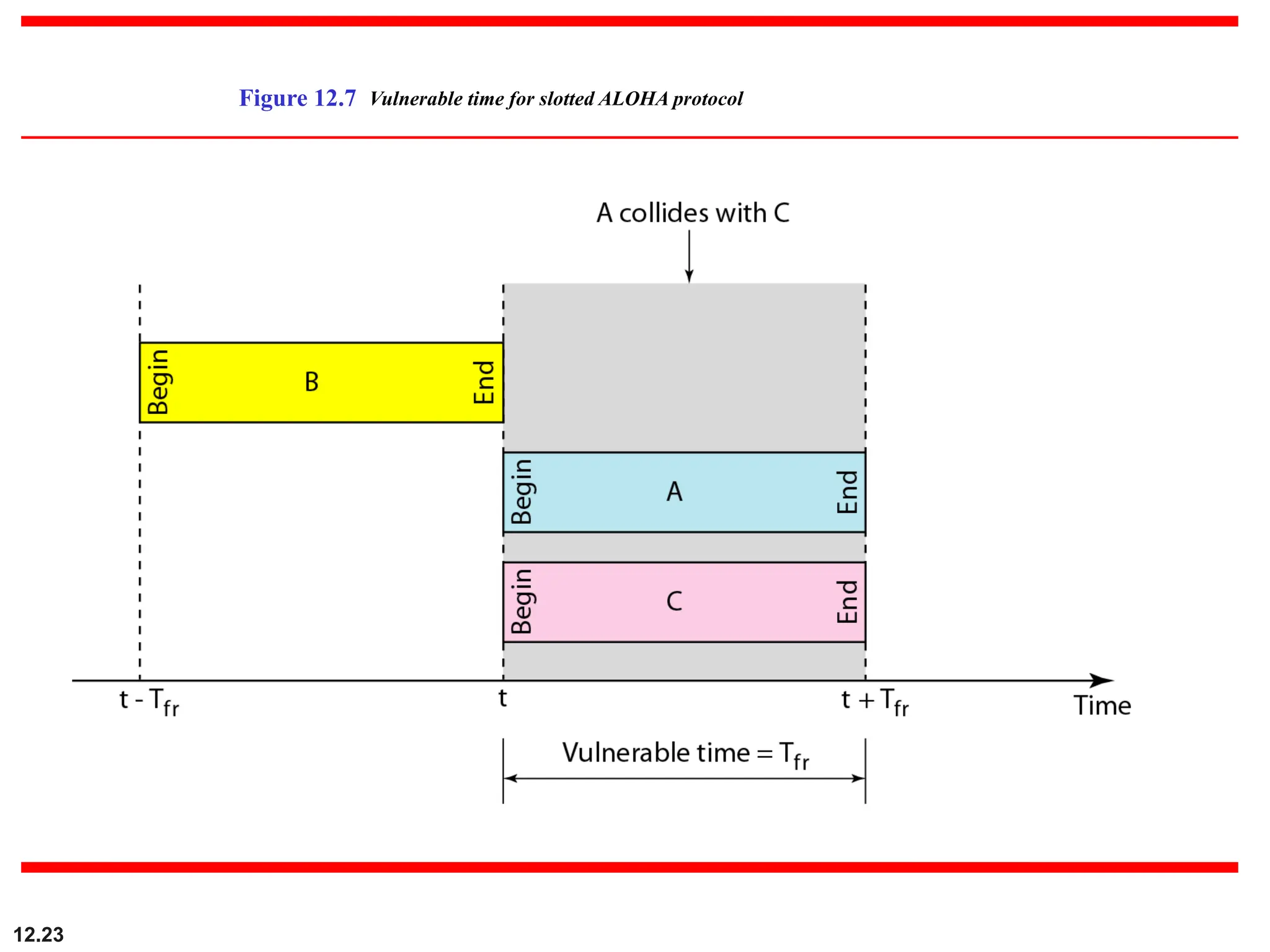
Figure 12.5 Vulnerabletime for pure ALOHA protocol
The stations send fixed-length frames with each frame taking Tfr seconds to send.
15.
12.15
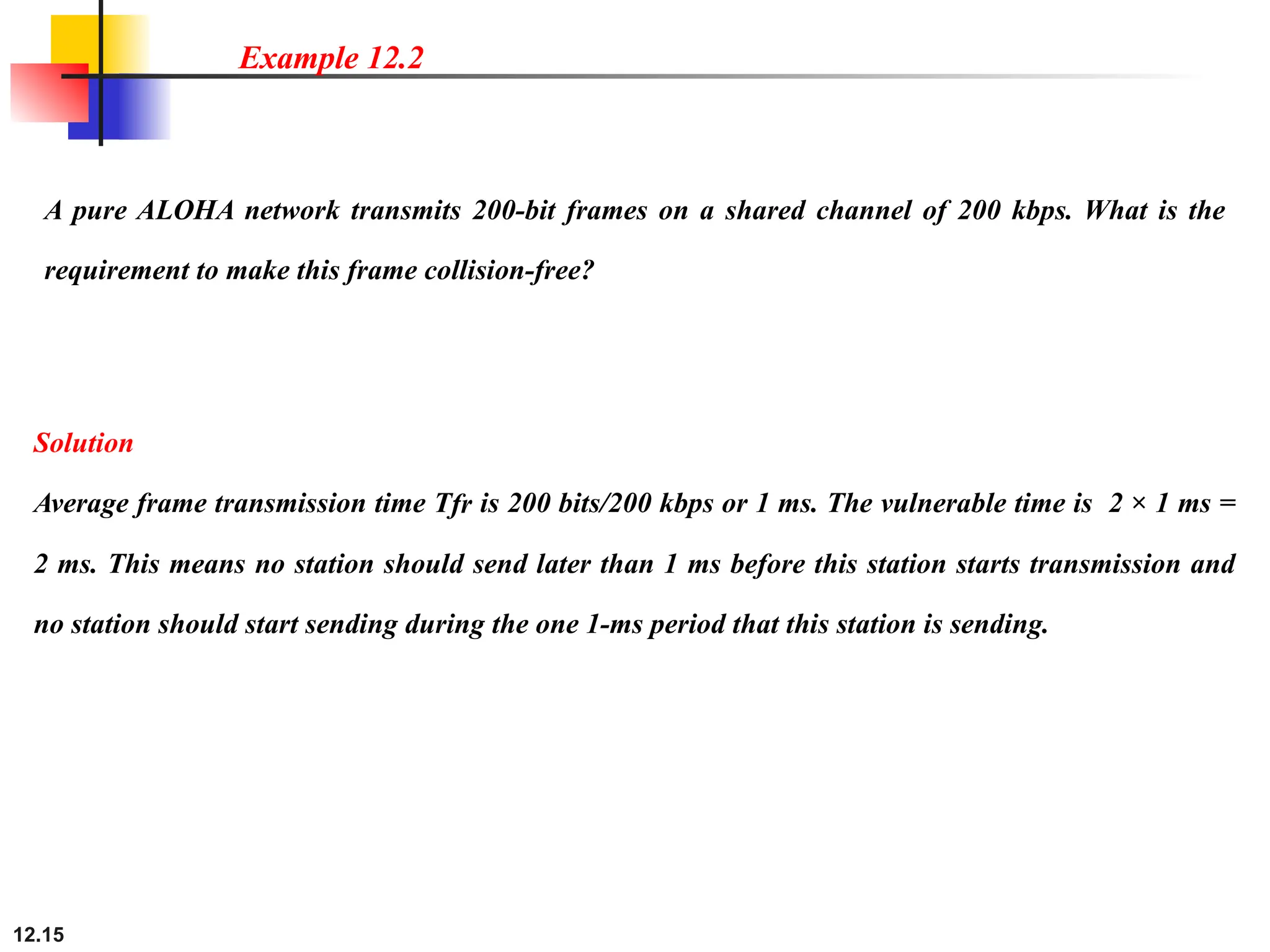
A pure ALOHAnetwork transmits 200-bit frames on a shared channel of 200 kbps. What is the
requirement to make this frame collision-free?
Example 12.2
Solution
Average frame transmission time Tfr is 200 bits/200 kbps or 1 ms. The vulnerable time is 2 × 1 ms =
2 ms. This means no station should send later than 1 ms before this station starts transmission and
no station should start sending during the one 1-ms period that this station is sending.
16.
12.16
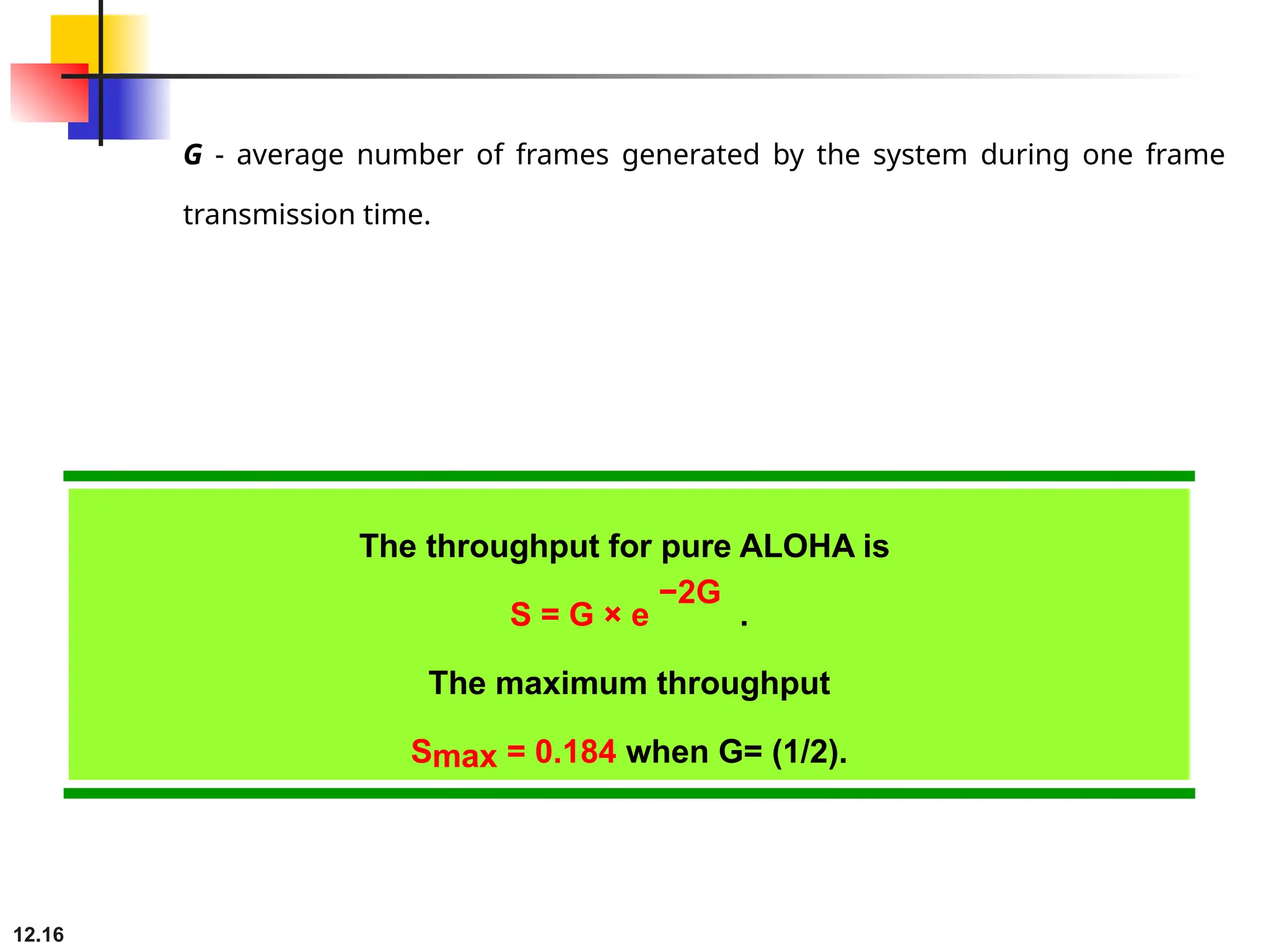
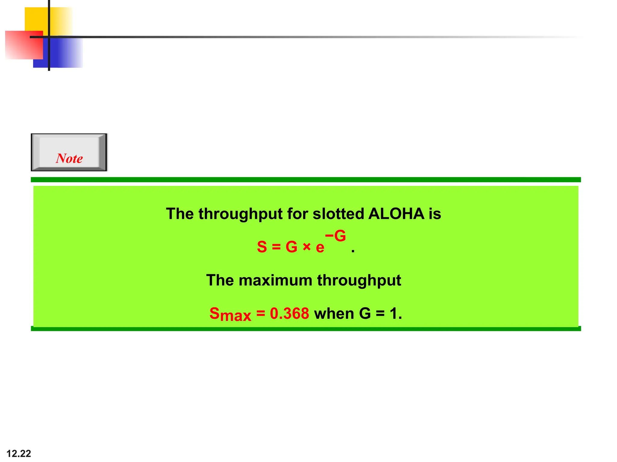
The throughput forpure ALOHA is
S = G × e
−2G
.
The maximum throughput
Smax = 0.184 when G= (1/2).
G - average number of frames generated by the system during one frame
transmission time.
17.
12.17
A pure ALOHAnetwork transmits 200-bit frames on a shared channel of 200 kbps. What is the
throughput if the system (all stations together) produces
a. 1000 frames per second b. 500 frames per second
c. 250 frames per second.
Example 12.3
Solution
The frame transmission time is 200/200 kbps or 1 ms.
a. If the system creates 1000 frames per second, this is 1
frame per millisecond. The load is 1. In this case
S = G× e
−2 G
or S = 0.135 (13.5 percent). This means
that the throughput is 1000 × 0.135 = 135 frames. Only
135 frames out of 1000 will probably survive.
18.
12.18
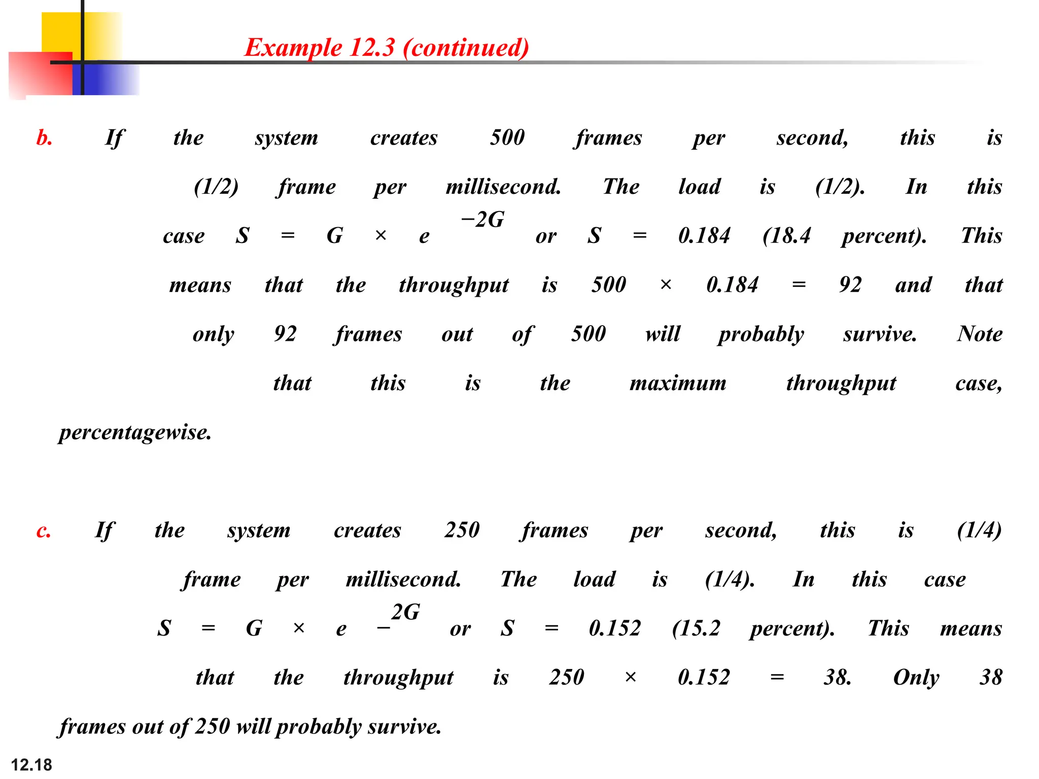
Example 12.3 (continued)
b.If the system creates 500 frames per second, this is
(1/2) frame per millisecond. The load is (1/2). In this
case S = G × e
−2G
or S = 0.184 (18.4 percent). This
means that the throughput is 500 × 0.184 = 92 and that
only 92 frames out of 500 will probably survive. Note
that this is the maximum throughput case,
percentagewise.
c. If the system creates 250 frames per second, this is (1/4)
frame per millisecond. The load is (1/4). In this case
S = G × e −
2G
or S = 0.152 (15.2 percent). This means
that the throughput is 250 × 0.152 = 38. Only 38
frames out of 250 will probably survive.
19.
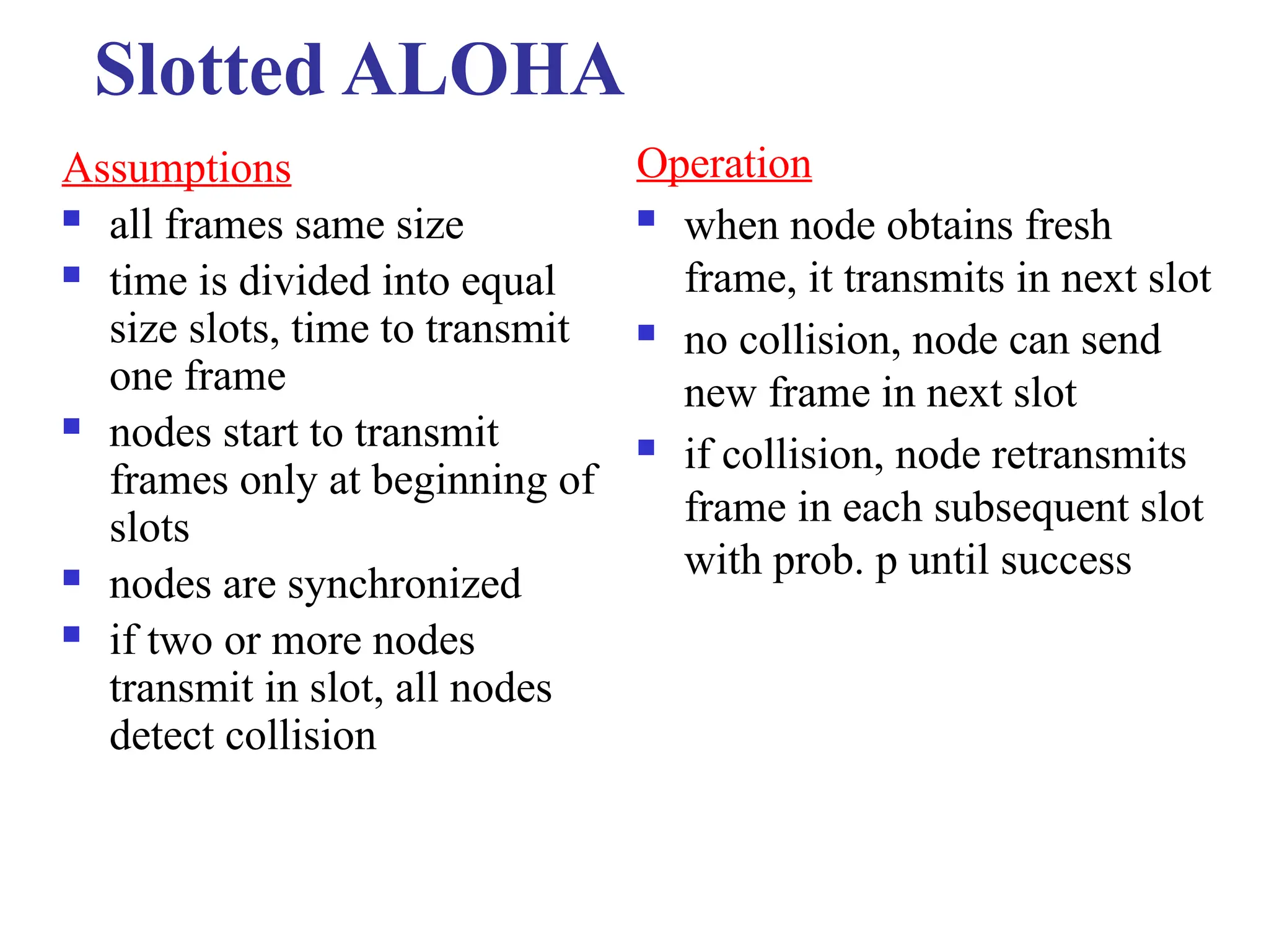
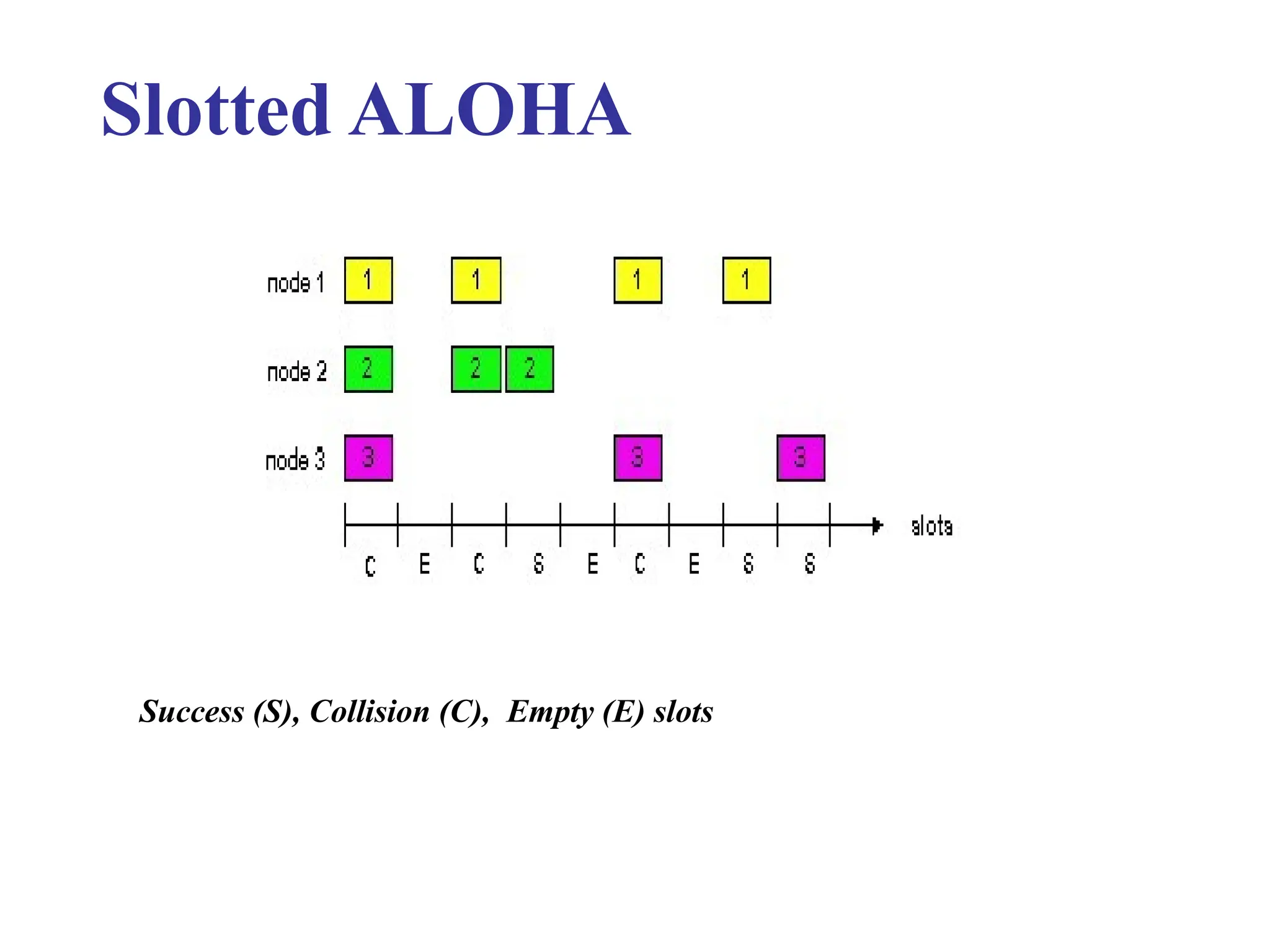
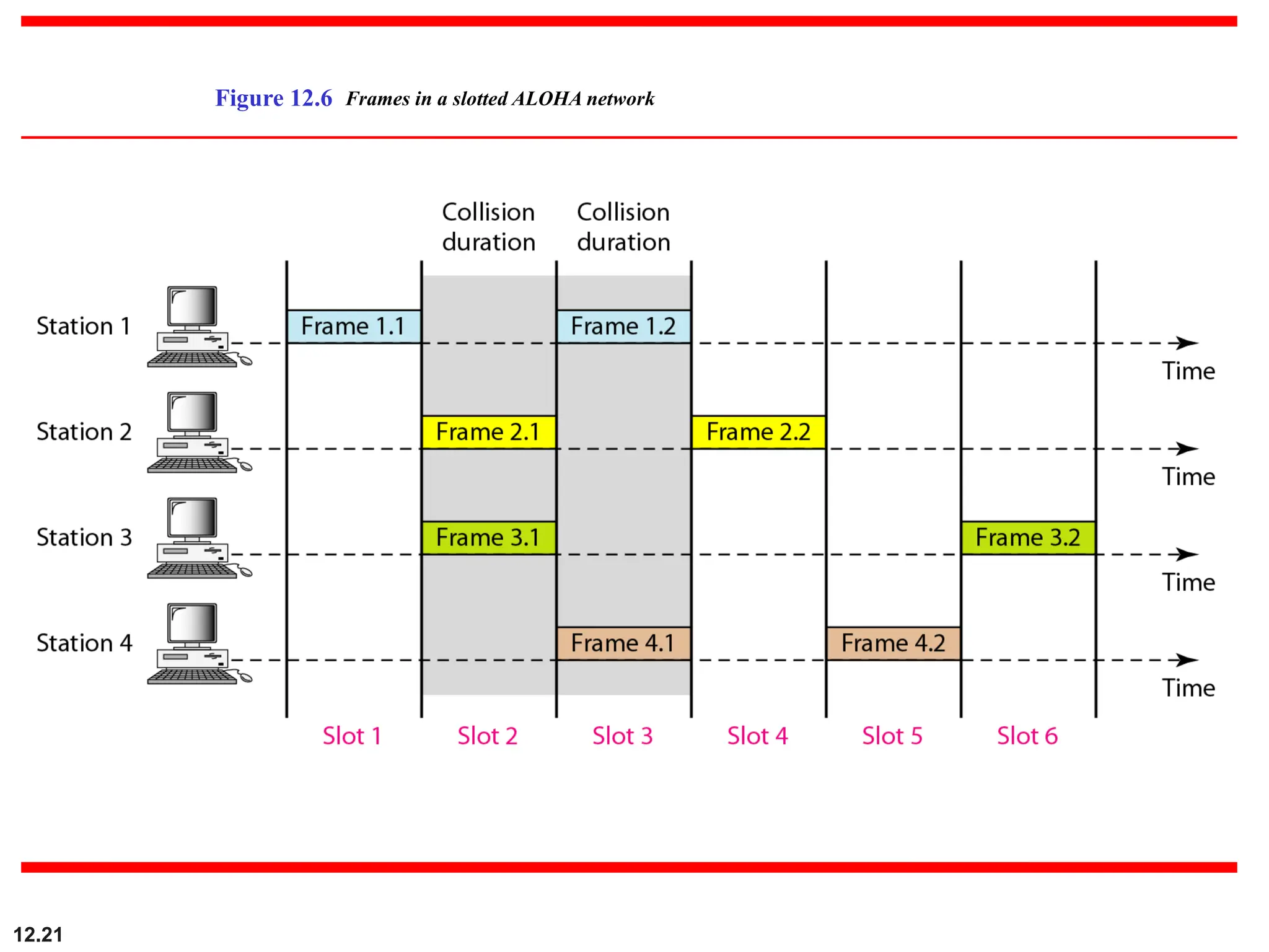
Slotted ALOHA
Assumptions
allframes same size
time is divided into equal
size slots, time to transmit
one frame
nodes start to transmit
frames only at beginning of
slots
nodes are synchronized
if two or more nodes
transmit in slot, all nodes
detect collision
Operation
when node obtains fresh
frame, it transmits in next slot
no collision, node can send
new frame in next slot
if collision, node retransmits
frame in each subsequent slot
with prob. p until success
12.24
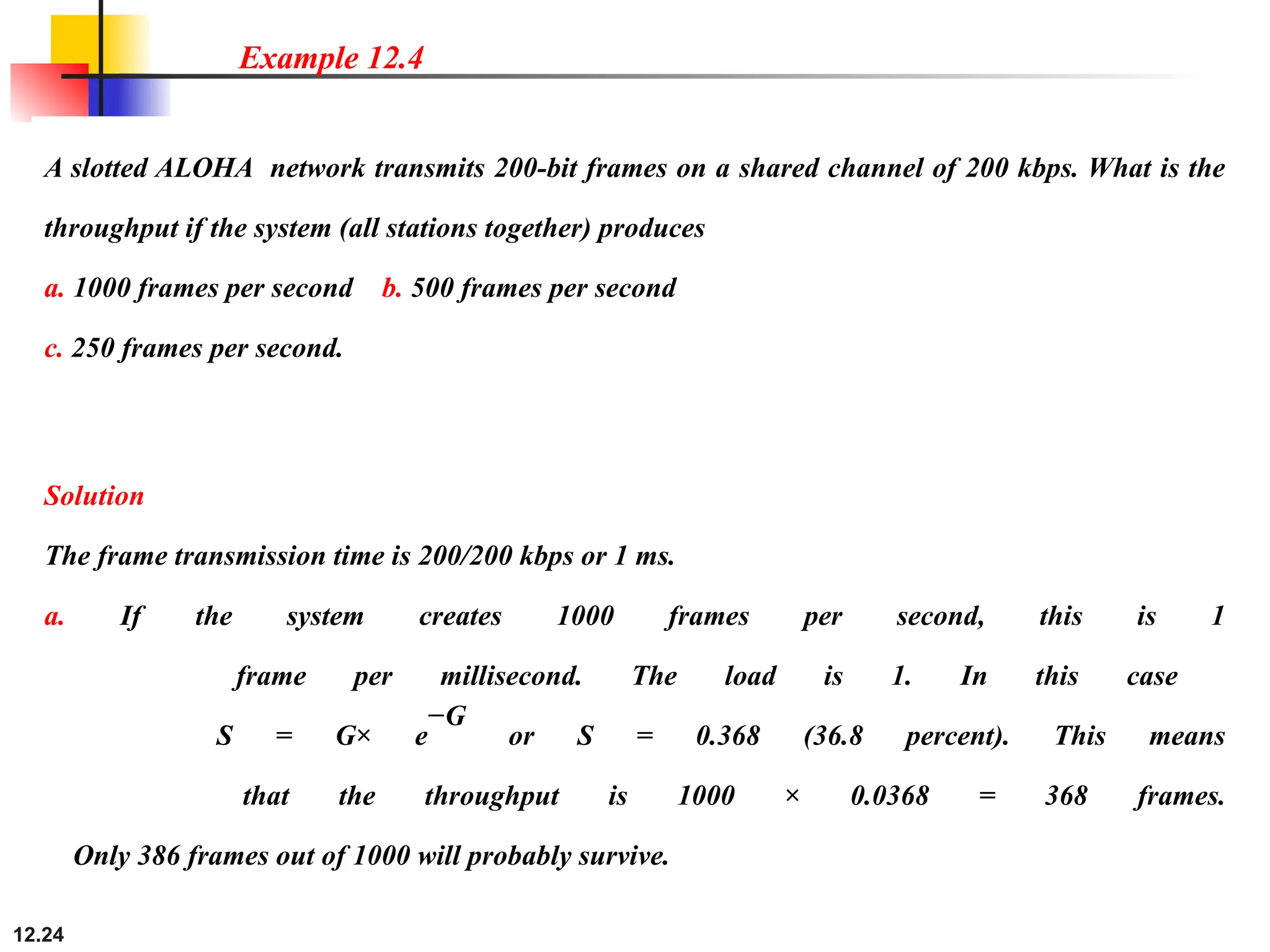
A slotted ALOHAnetwork transmits 200-bit frames on a shared channel of 200 kbps. What is the
throughput if the system (all stations together) produces
a. 1000 frames per second b. 500 frames per second
c. 250 frames per second.
Example 12.4
Solution
The frame transmission time is 200/200 kbps or 1 ms.
a. If the system creates 1000 frames per second, this is 1
frame per millisecond. The load is 1. In this case
S = G× e
−G
or S = 0.368 (36.8 percent). This means
that the throughput is 1000 × 0.0368 = 368 frames.
Only 386 frames out of 1000 will probably survive.
25.
12.25
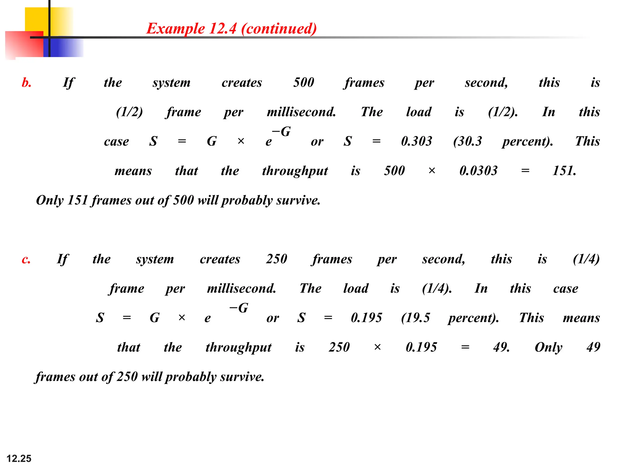
Example 12.4 (continued)
b.If the system creates 500 frames per second, this is
(1/2) frame per millisecond. The load is (1/2). In this
case S = G × e
−G
or S = 0.303 (30.3 percent). This
means that the throughput is 500 × 0.0303 = 151.
Only 151 frames out of 500 will probably survive.
c. If the system creates 250 frames per second, this is (1/4)
frame per millisecond. The load is (1/4). In this case
S = G × e
−G
or S = 0.195 (19.5 percent). This means
that the throughput is 250 × 0.195 = 49. Only 49
frames out of 250 will probably survive.
26.
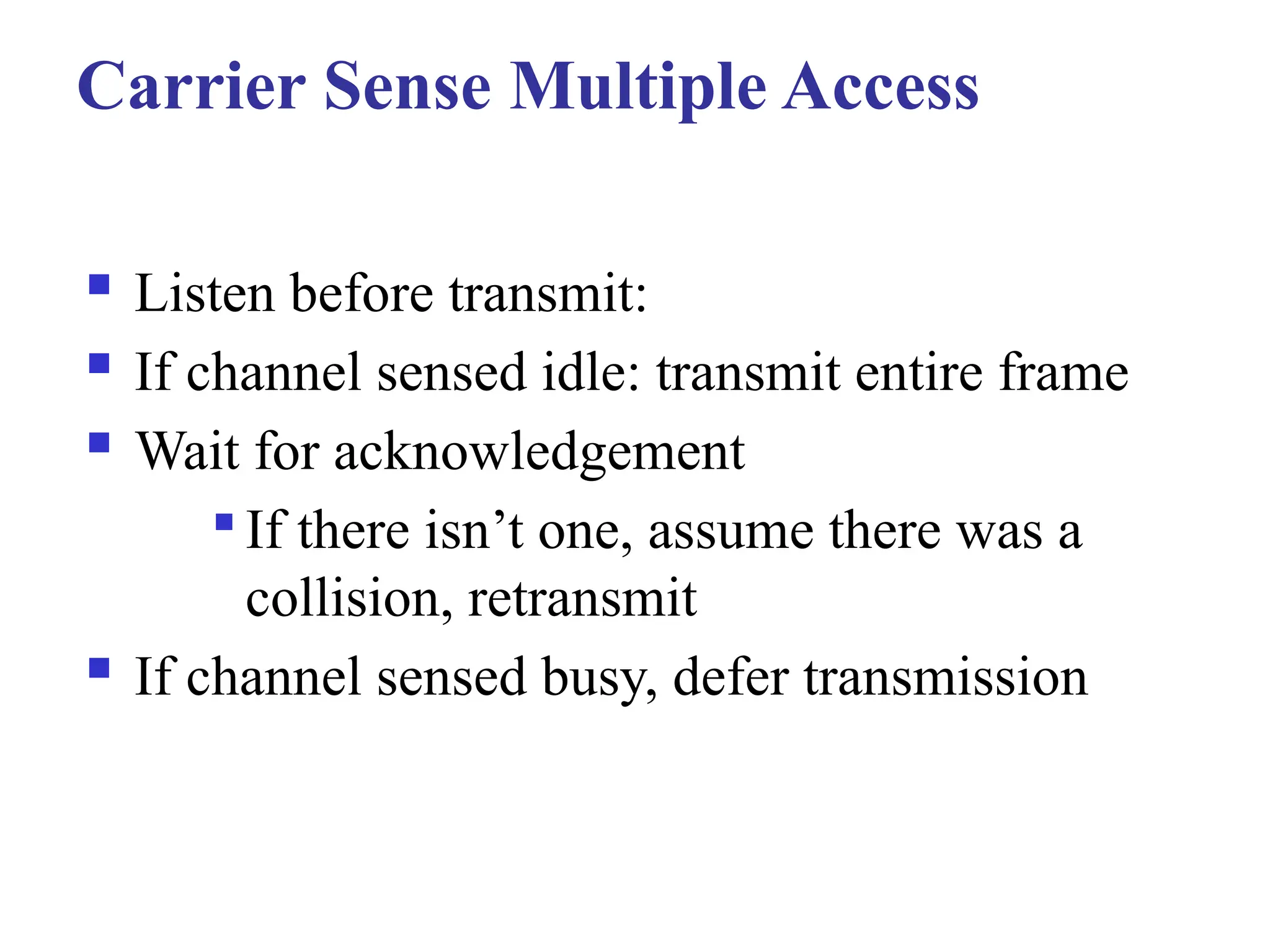
Carrier Sense MultipleAccess
Listen before transmit:
If channel sensed idle: transmit entire frame
Wait for acknowledgement
If there isn’t one, assume there was a
collision, retransmit
If channel sensed busy, defer transmission
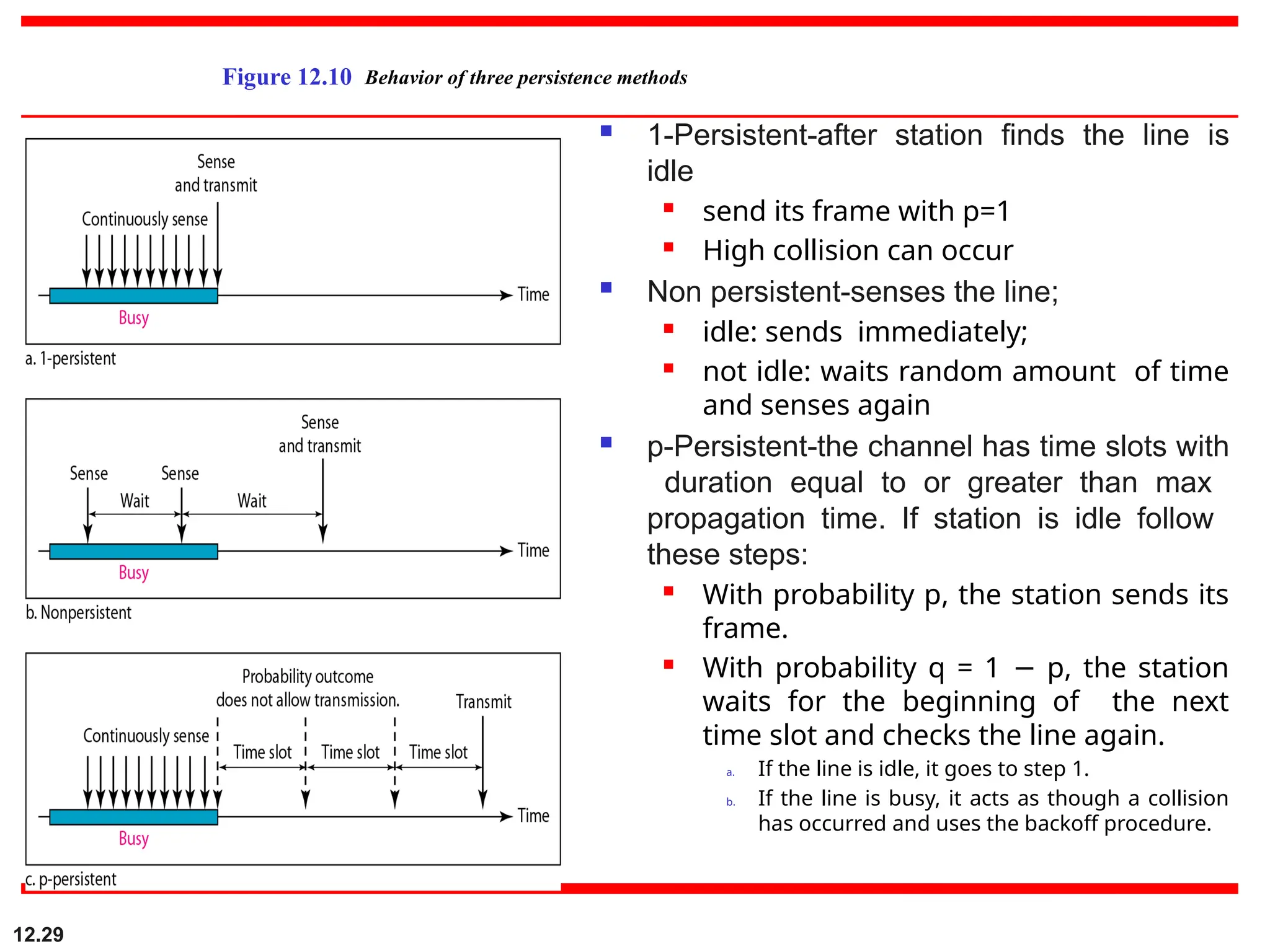
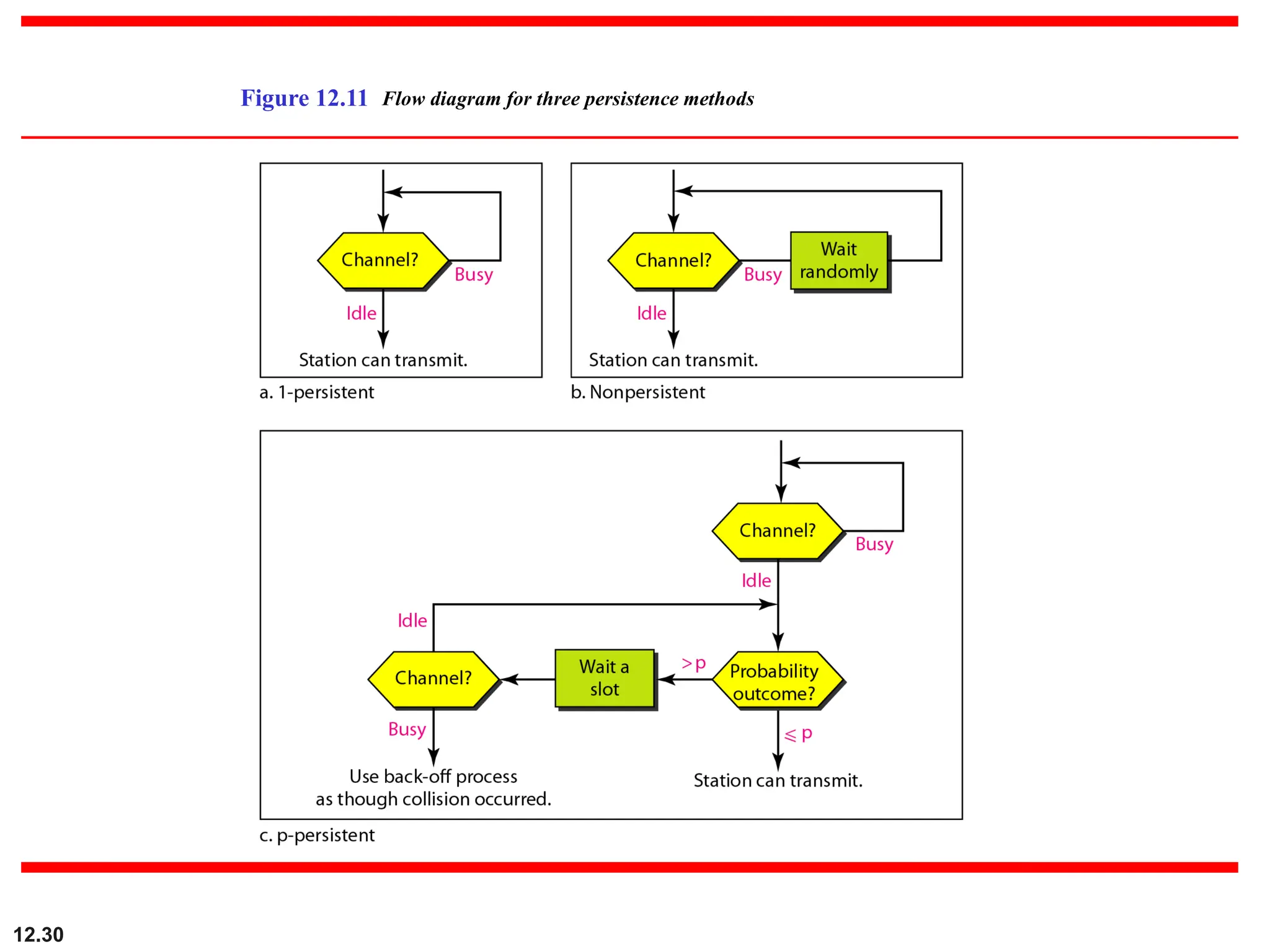
1-Persistent-after stationfinds the line is
idle
send its frame with p=1
High collision can occur
Non persistent-senses the line;
idle: sends immediately;
not idle: waits random amount of time
and senses again
p-Persistent-the channel has time slots with
duration equal to or greater than max
propagation time. If station is idle follow
these steps:
With probability p, the station sends its
frame.
With probability q = 1 p, the station
−
waits for the beginning of the next
time slot and checks the line again.
a. If the line is idle, it goes to step 1.
b. If the line is busy, it acts as though a collision
has occurred and uses the backoff procedure.
12.29
Figure 12.10 Behavior of three persistence methods
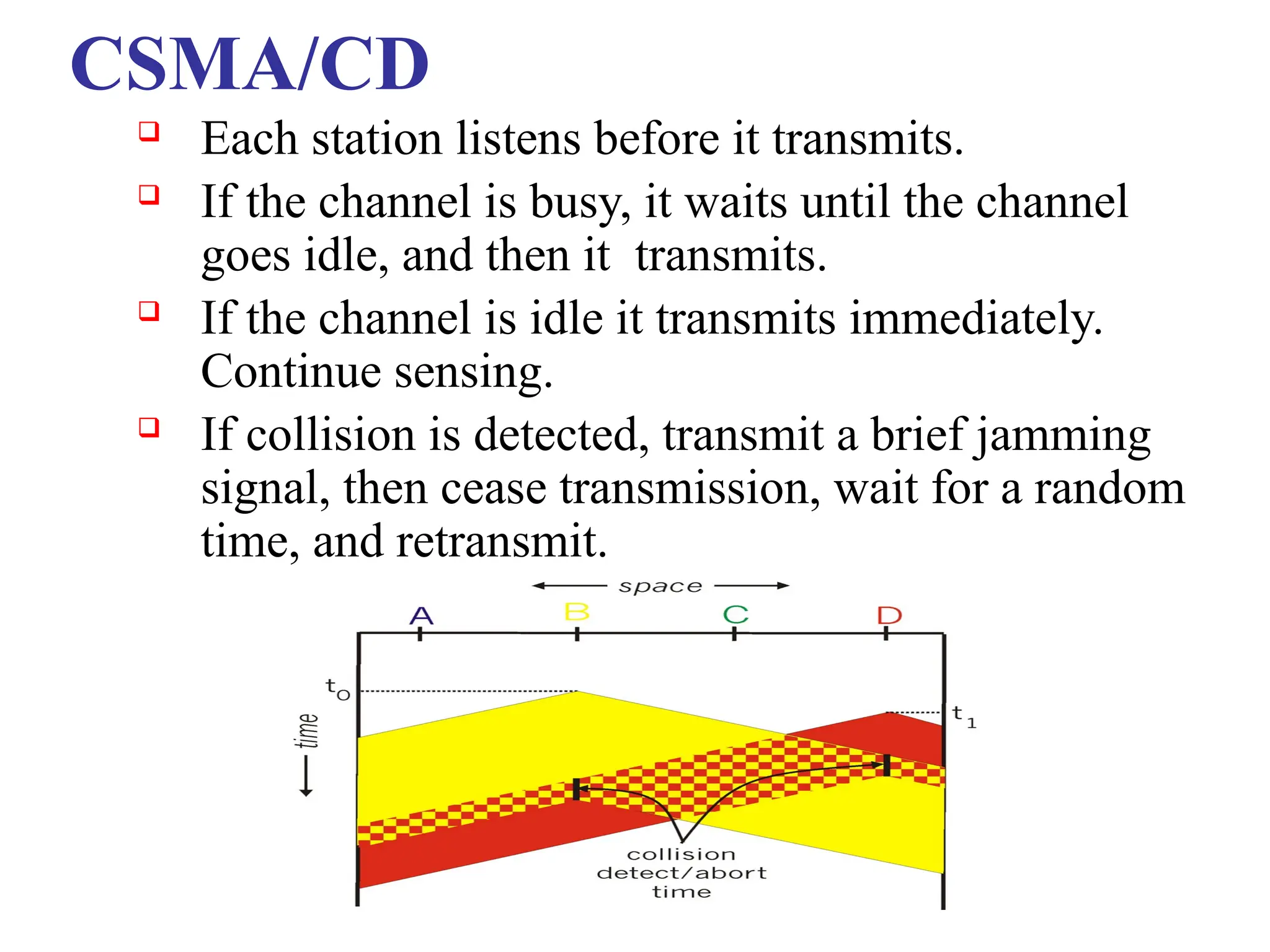
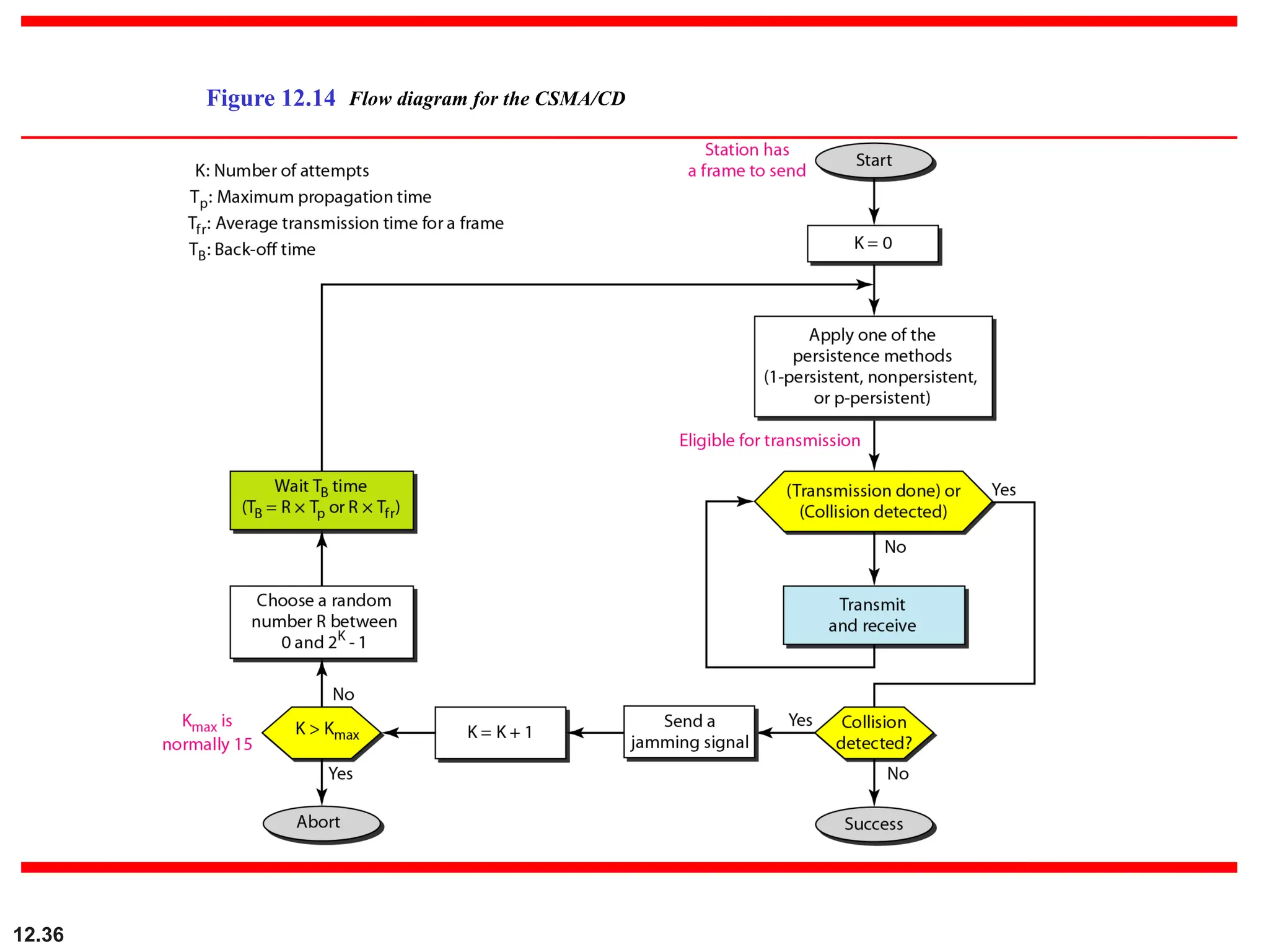
CSMA/CD
Each stationlistens before it transmits.
If the channel is busy, it waits until the channel
goes idle, and then it transmits.
If the channel is idle it transmits immediately.
Continue sensing.
If collision is detected, transmit a brief jamming
signal, then cease transmission, wait for a random
time, and retransmit.
CSMA/CD
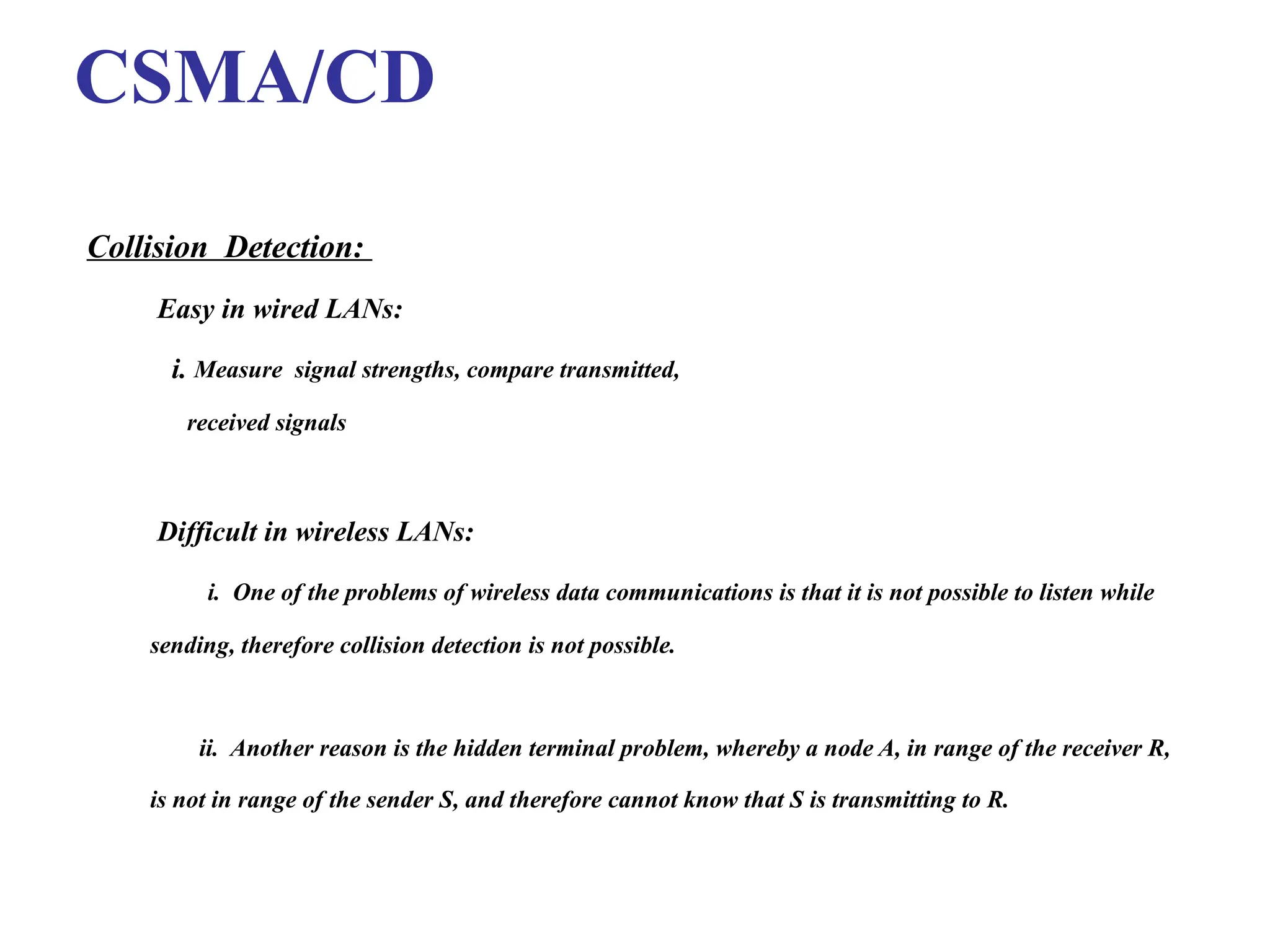
Collision Detection:
Easy inwired LANs:
i. Measure signal strengths, compare transmitted,
received signals
Difficult in wireless LANs:
i. One of the problems of wireless data communications is that it is not possible to listen while
sending, therefore collision detection is not possible.
ii. Another reason is the hidden terminal problem, whereby a node A, in range of the receiver R,
is not in range of the sender S, and therefore cannot know that S is transmitting to R.
35.
12.35
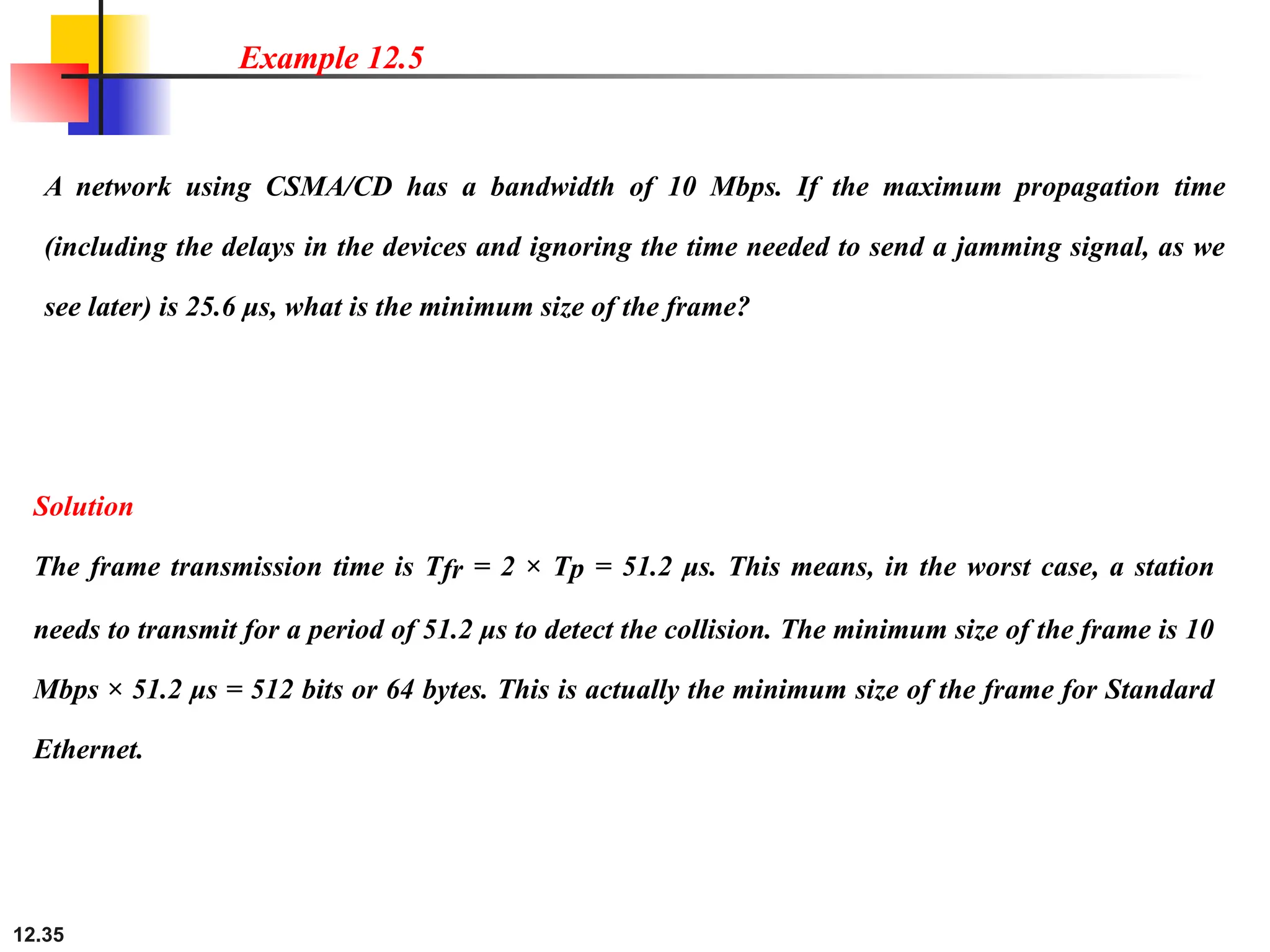
A network usingCSMA/CD has a bandwidth of 10 Mbps. If the maximum propagation time
(including the delays in the devices and ignoring the time needed to send a jamming signal, as we
see later) is 25.6 μs, what is the minimum size of the frame?
Example 12.5
Solution
The frame transmission time is Tfr = 2 × Tp = 51.2 μs. This means, in the worst case, a station
needs to transmit for a period of 51.2 μs to detect the collision. The minimum size of the frame is 10
Mbps × 51.2 μs = 512 bits or 64 bytes. This is actually the minimum size of the frame for Standard
Ethernet.
12.42
12-2 CONTROLLED ACCESS
Incontrolled access, the stations consult one another to find which station has the right to
send. A station cannot send unless it has been authorized by other stations. We discuss three
popular controlled-access methods.
Reservation
Polling
Token Passing
Topics discussed in this section:
39.
12.43
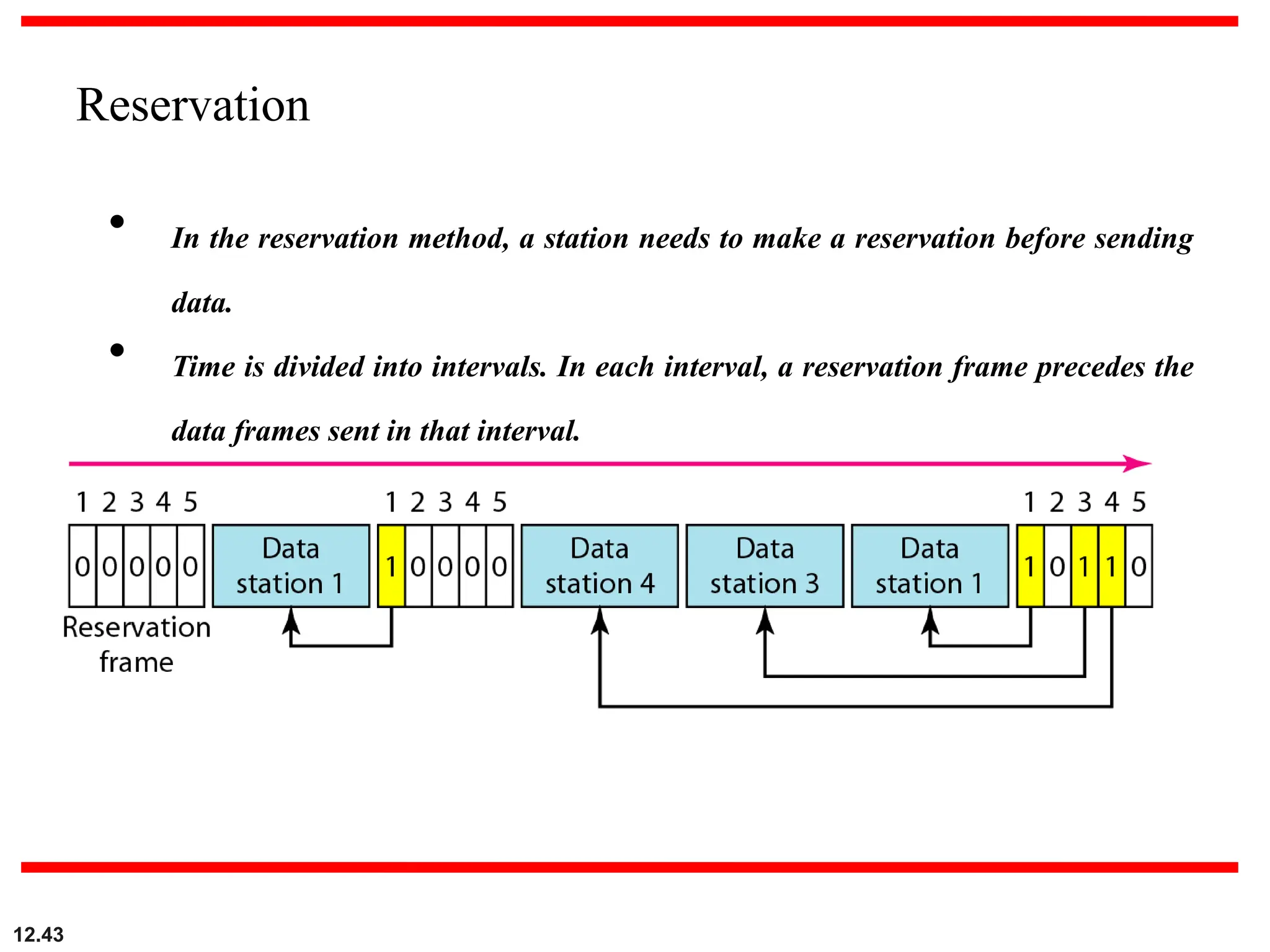
• In thereservation method, a station needs to make a reservation before sending
data.
• Time is divided into intervals. In each interval, a reservation frame precedes the
data frames sent in that interval.
Reservation
40.
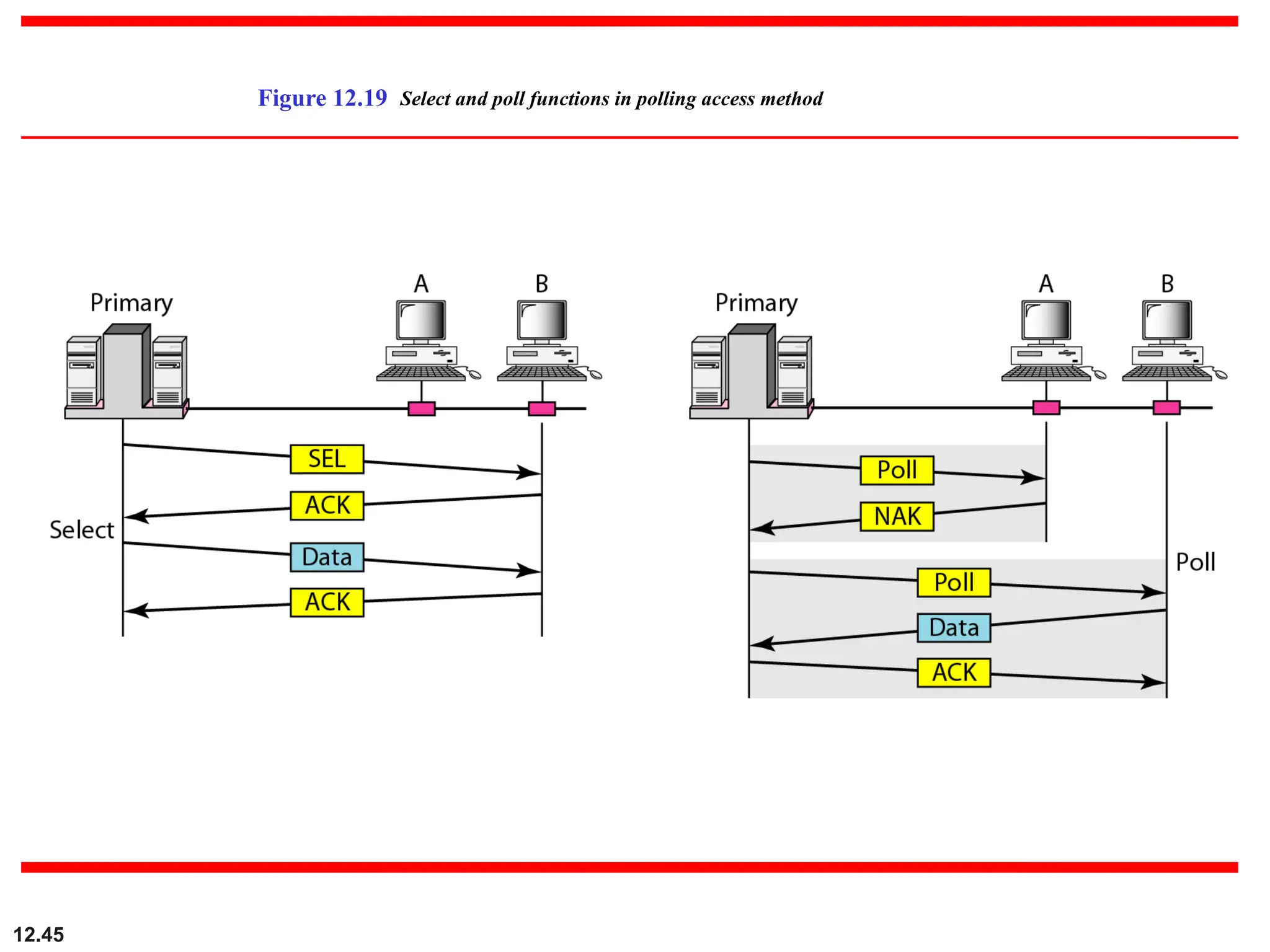
Polling
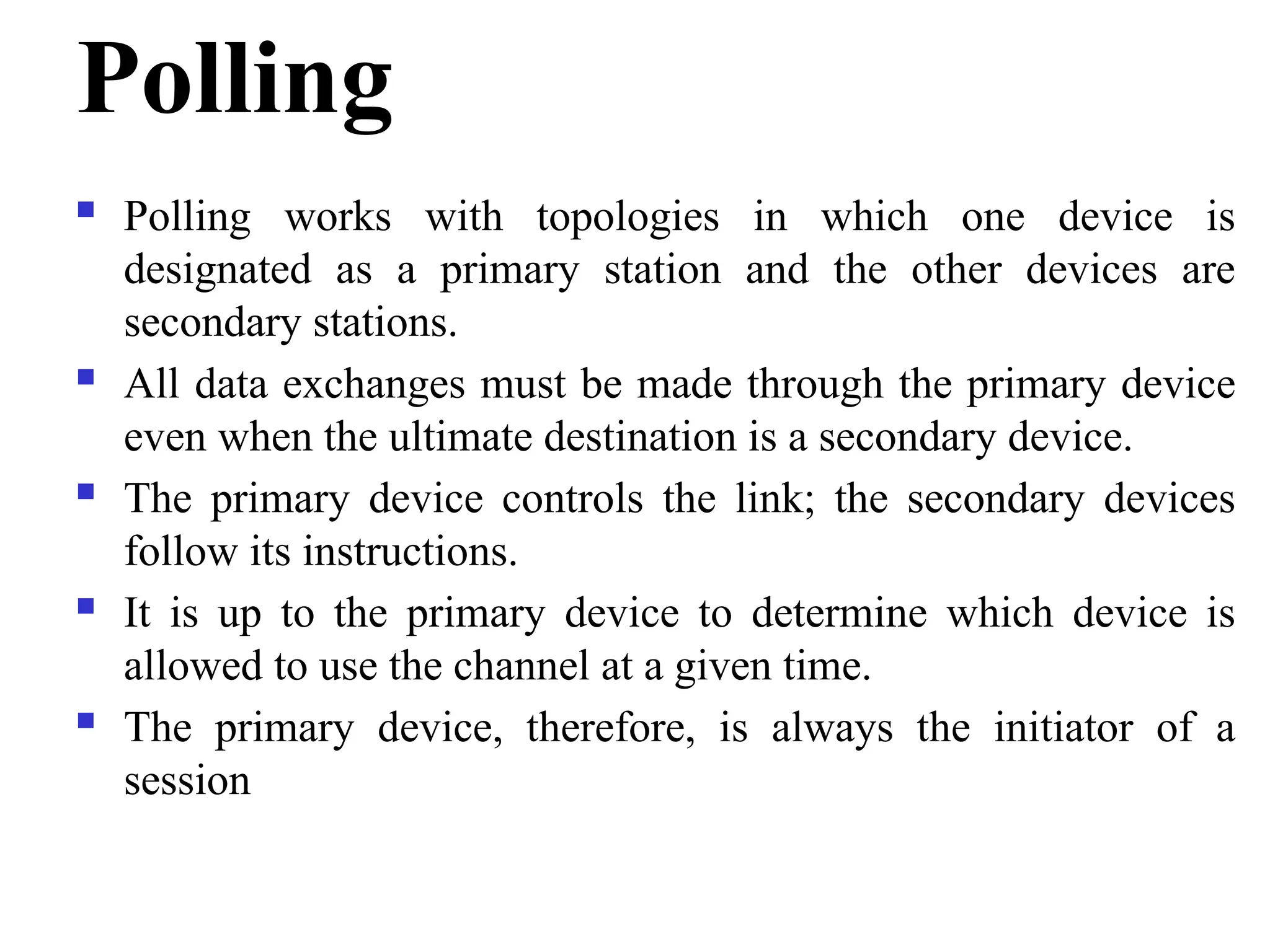
Polling workswith topologies in which one device is
designated as a primary station and the other devices are
secondary stations.
All data exchanges must be made through the primary device
even when the ultimate destination is a secondary device.
The primary device controls the link; the secondary devices
follow its instructions.
It is up to the primary device to determine which device is
allowed to use the channel at a given time.
The primary device, therefore, is always the initiator of a
session
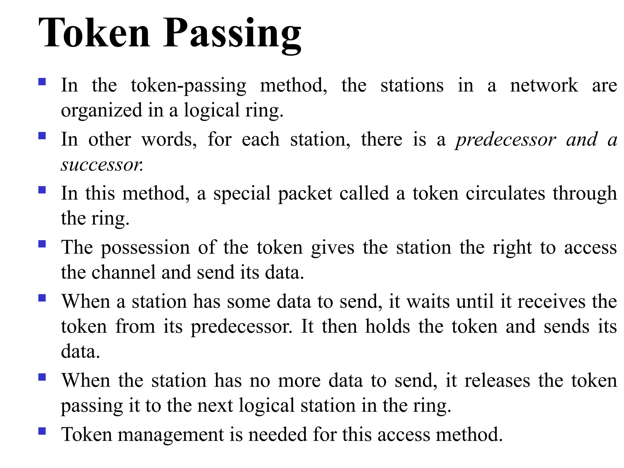
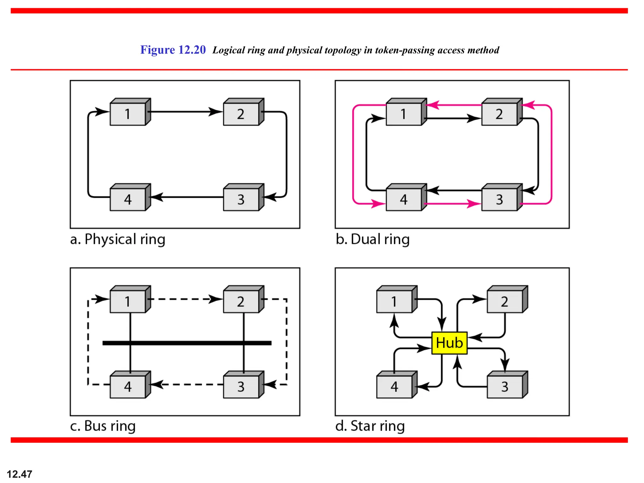
Token Passing
Inthe token-passing method, the stations in a network are
organized in a logical ring.
In other words, for each station, there is a predecessor and a
successor.
In this method, a special packet called a token circulates through
the ring.
The possession of the token gives the station the right to access
the channel and send its data.
When a station has some data to send, it waits until it receives the
token from its predecessor. It then holds the token and sends its
data.
When the station has no more data to send, it releases the token
passing it to the next logical station in the ring.
Token management is needed for this access method.
12.48
12-3 CHANNELIZATION
Channelization isa multiple-access method in which the available bandwidth of a link is
shared in time, frequency, or through code, between different stations. In this section, we
discuss three channelization protocols.
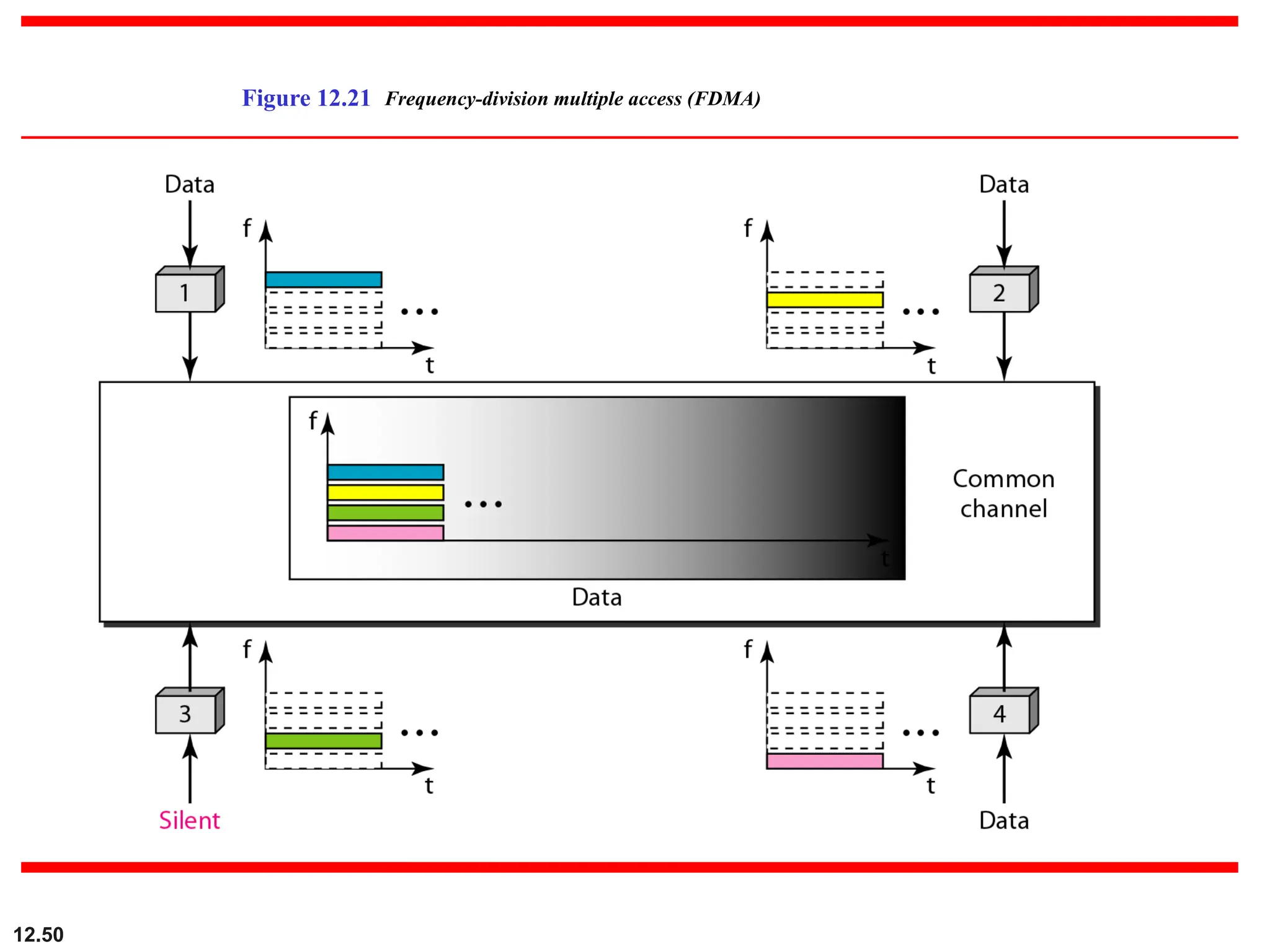
Frequency-Division Multiple Access (FDMA)
Time-Division Multiple Access (TDMA)
Code-Division Multiple Access (CDMA)
Topics discussed in this section:
45.
FDMA (Frequency DivisionMultiple Access)
In frequency-division multiple access (FDMA), the
available bandwidth is divided into frequency bands.
Each station is allocated a band to send its data.
In other words, each band is reserved for a specific
station, and it belongs to the station all the time.
Example :Radio broadcast
12.51
In FDMA, theavailable bandwidth
of the common channel is divided into bands that are separated by
guard bands.
Note
48.
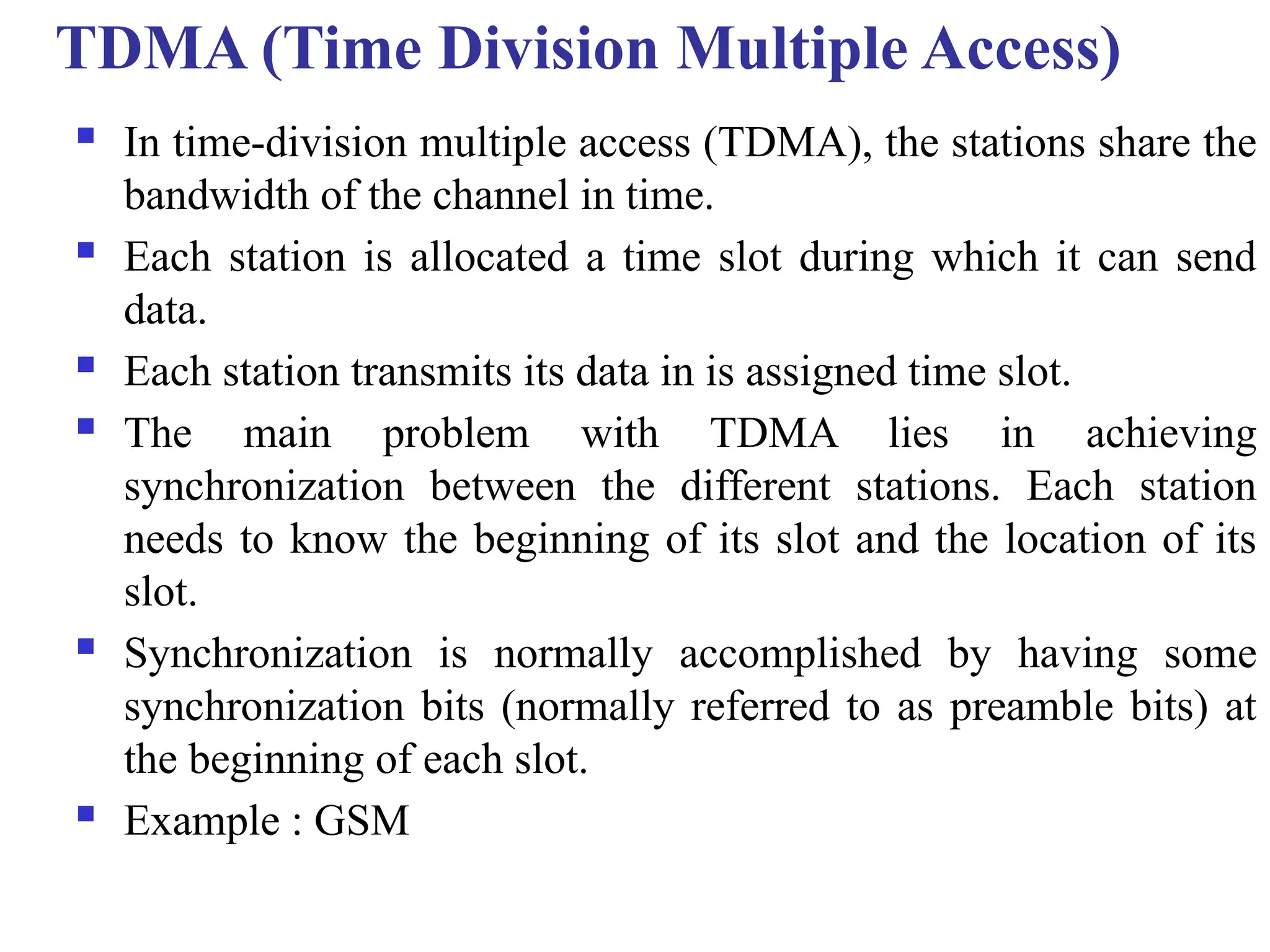
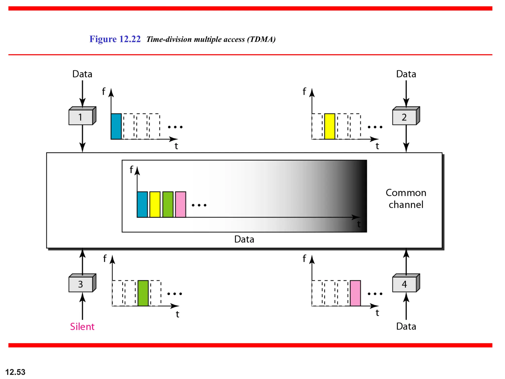
TDMA (Time DivisionMultiple Access)
In time-division multiple access (TDMA), the stations share the
bandwidth of the channel in time.
Each station is allocated a time slot during which it can send
data.
Each station transmits its data in is assigned time slot.
The main problem with TDMA lies in achieving
synchronization between the different stations. Each station
needs to know the beginning of its slot and the location of its
slot.
Synchronization is normally accomplished by having some
synchronization bits (normally referred to as preamble bits) at
the beginning of each slot.
Example : GSM
12.54
In TDMA, thebandwidth is just one channel that is timeshared
between different stations.
Note
51.
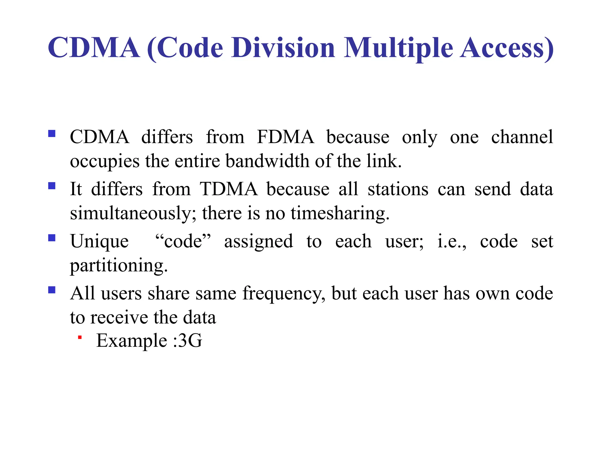
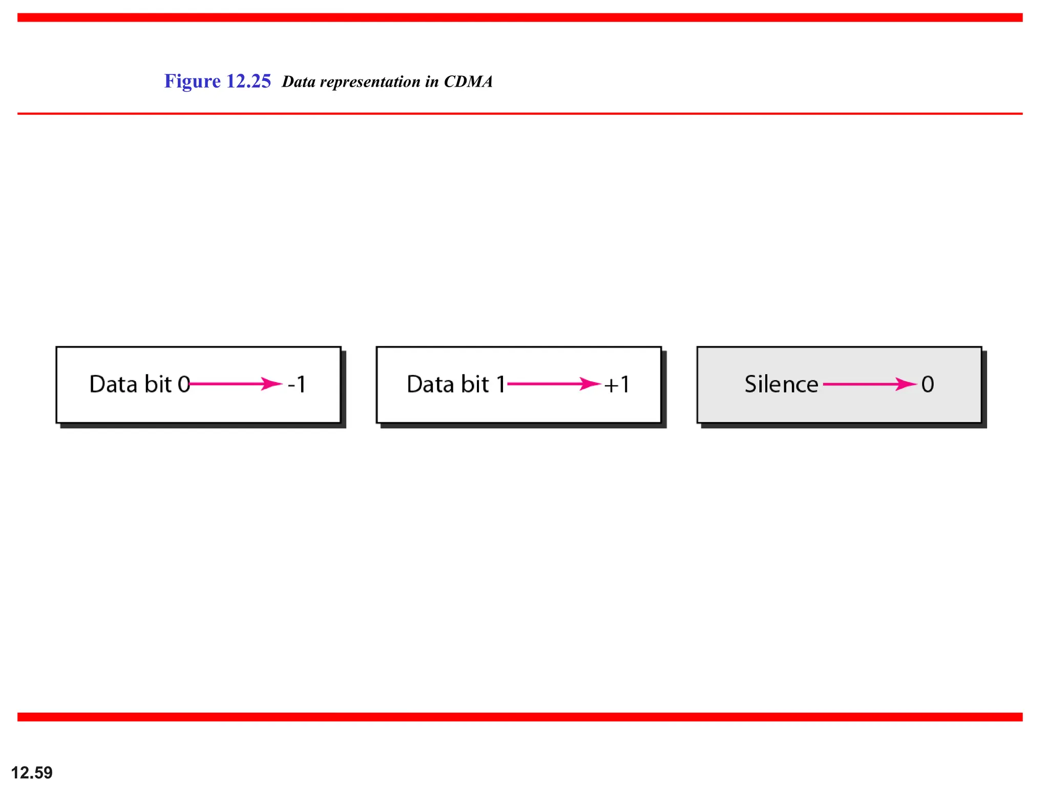
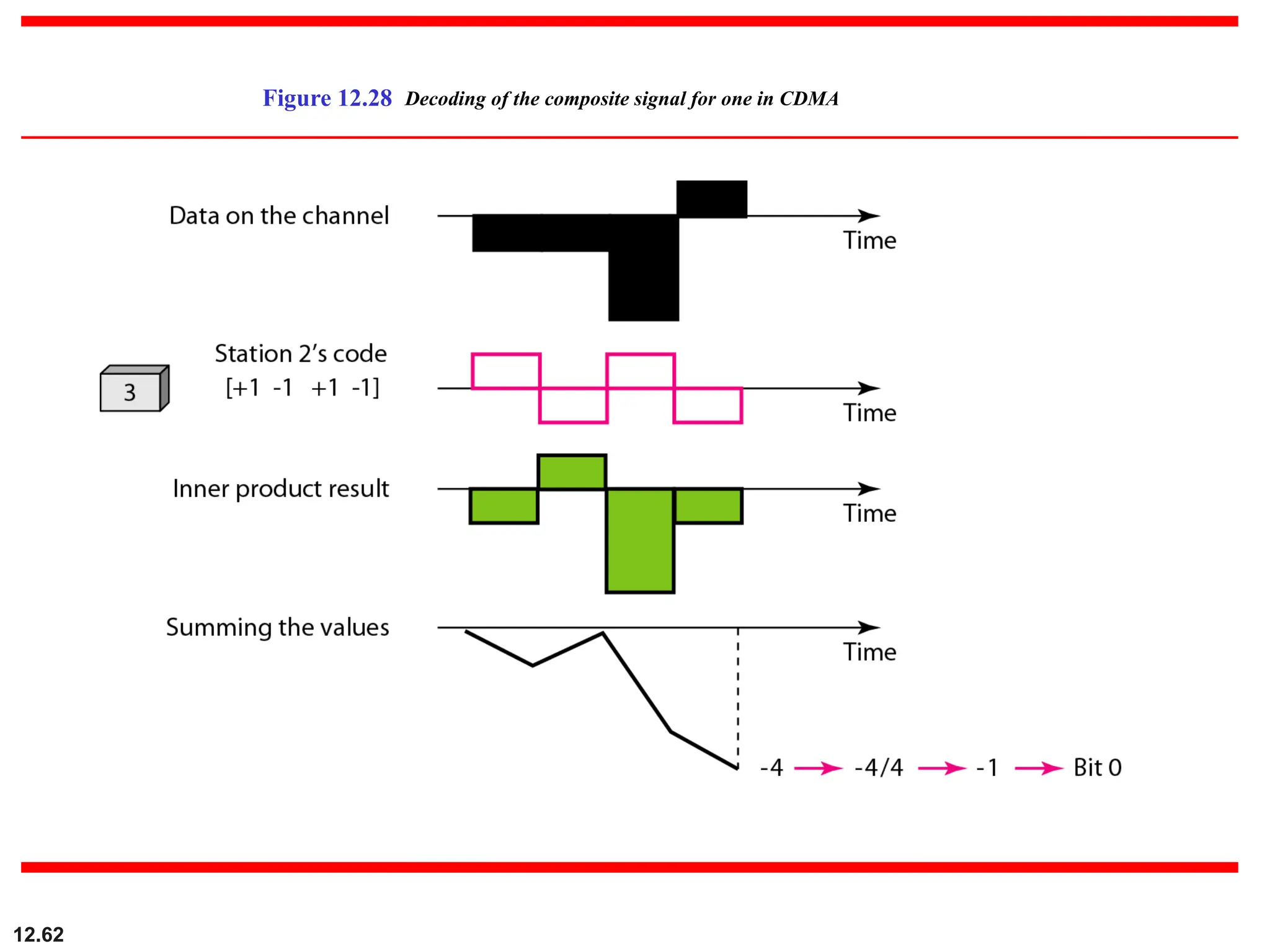
CDMA (Code DivisionMultiple Access)
CDMA differs from FDMA because only one channel
occupies the entire bandwidth of the link.
It differs from TDMA because all stations can send data
simultaneously; there is no timesharing.
Unique “code” assigned to each user; i.e., code set
partitioning.
All users share same frequency, but each user has own code
to receive the data
Example :3G
52.
12.56
In CDMA, onechannel carries all transmissions simultaneously.
Note
12.65
Find the chipsfor a network with
a. Two stations b. Four stations
Example 12.6
Solution
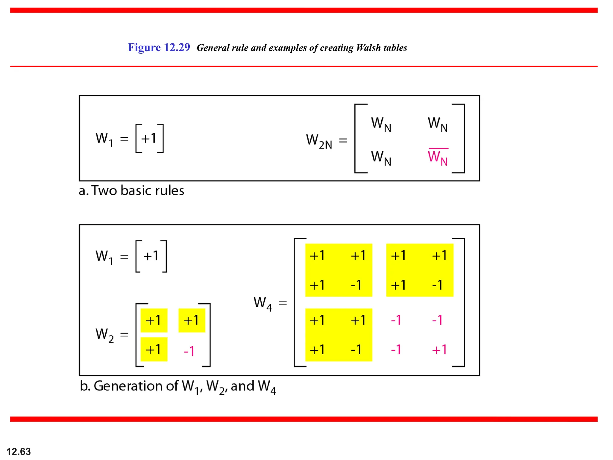
We can use the rows of W2 and W4 in Figure 12.29:
a. For a two-station network, we have
[+1 +1] and [+1 −1].
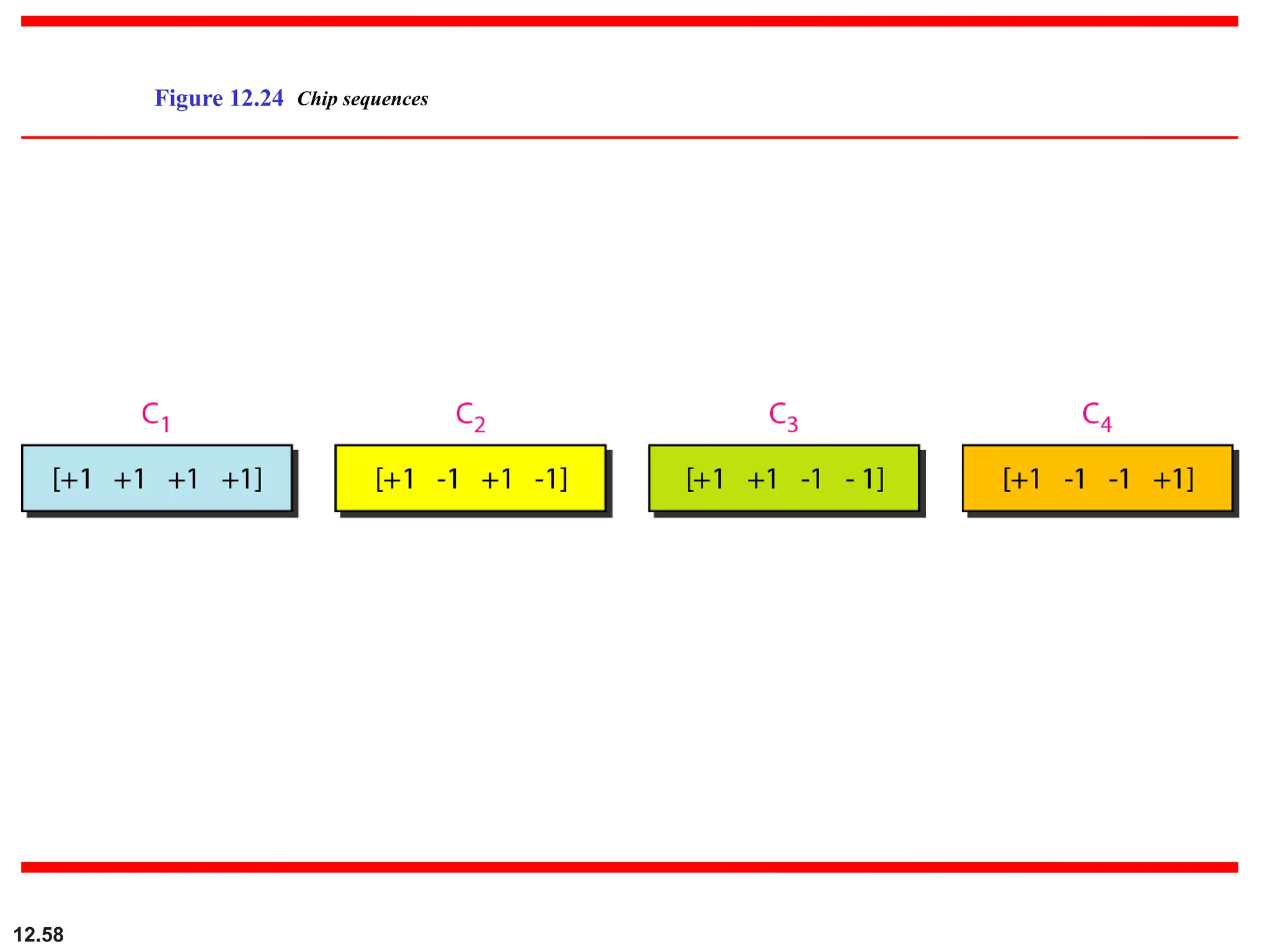
b. For a four-station network we have
[+1 +1 +1 +1], [+1 −1 +1 −1],
[+1 +1 −1 −1], and [+1 −1 −1 +1].
62.
12.66
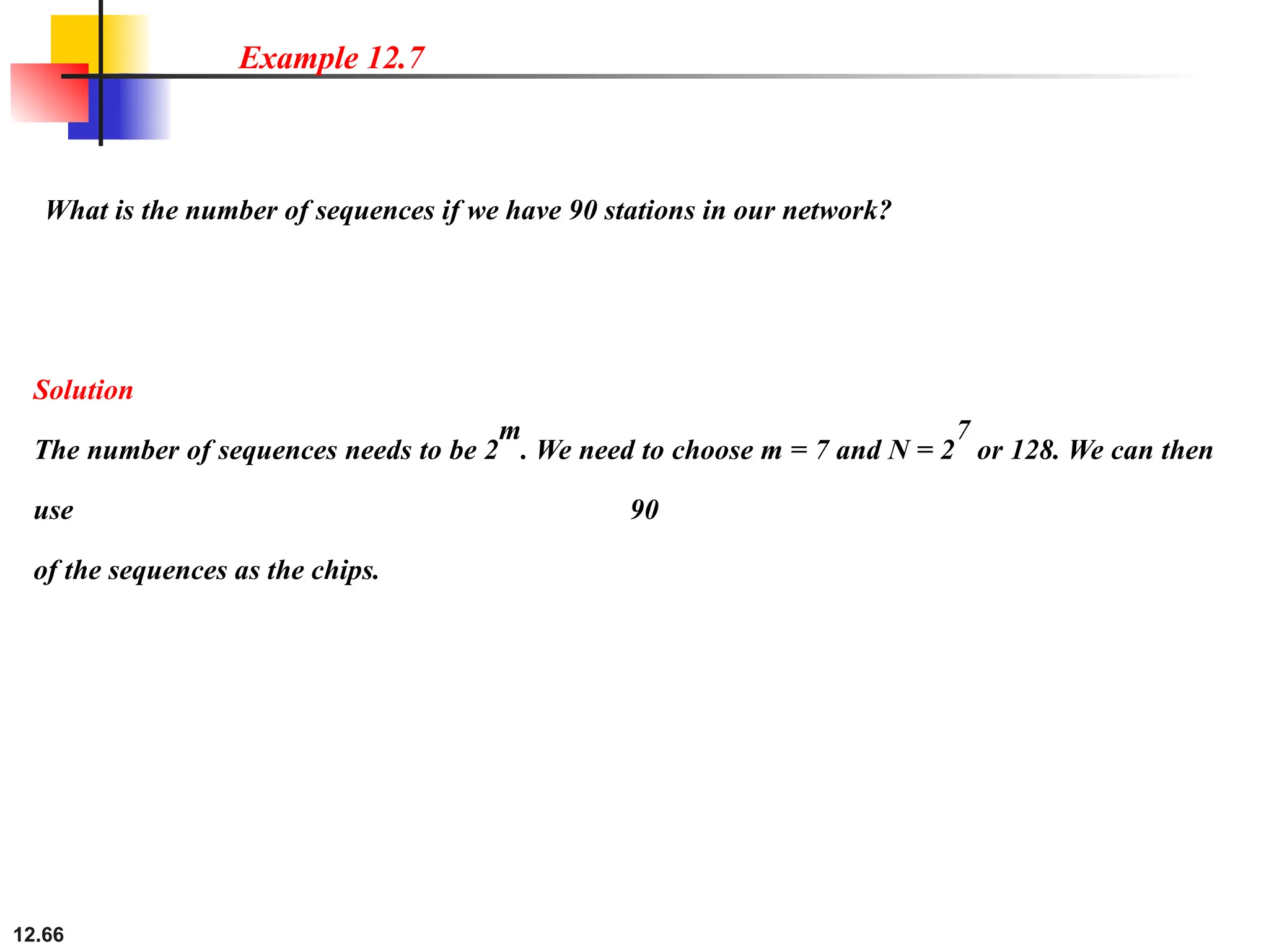
What is thenumber of sequences if we have 90 stations in our network?
Example 12.7
Solution
The number of sequences needs to be 2
m
. We need to choose m = 7 and N = 2
7
or 128. We can then
use 90
of the sequences as the chips.
63.
12.67
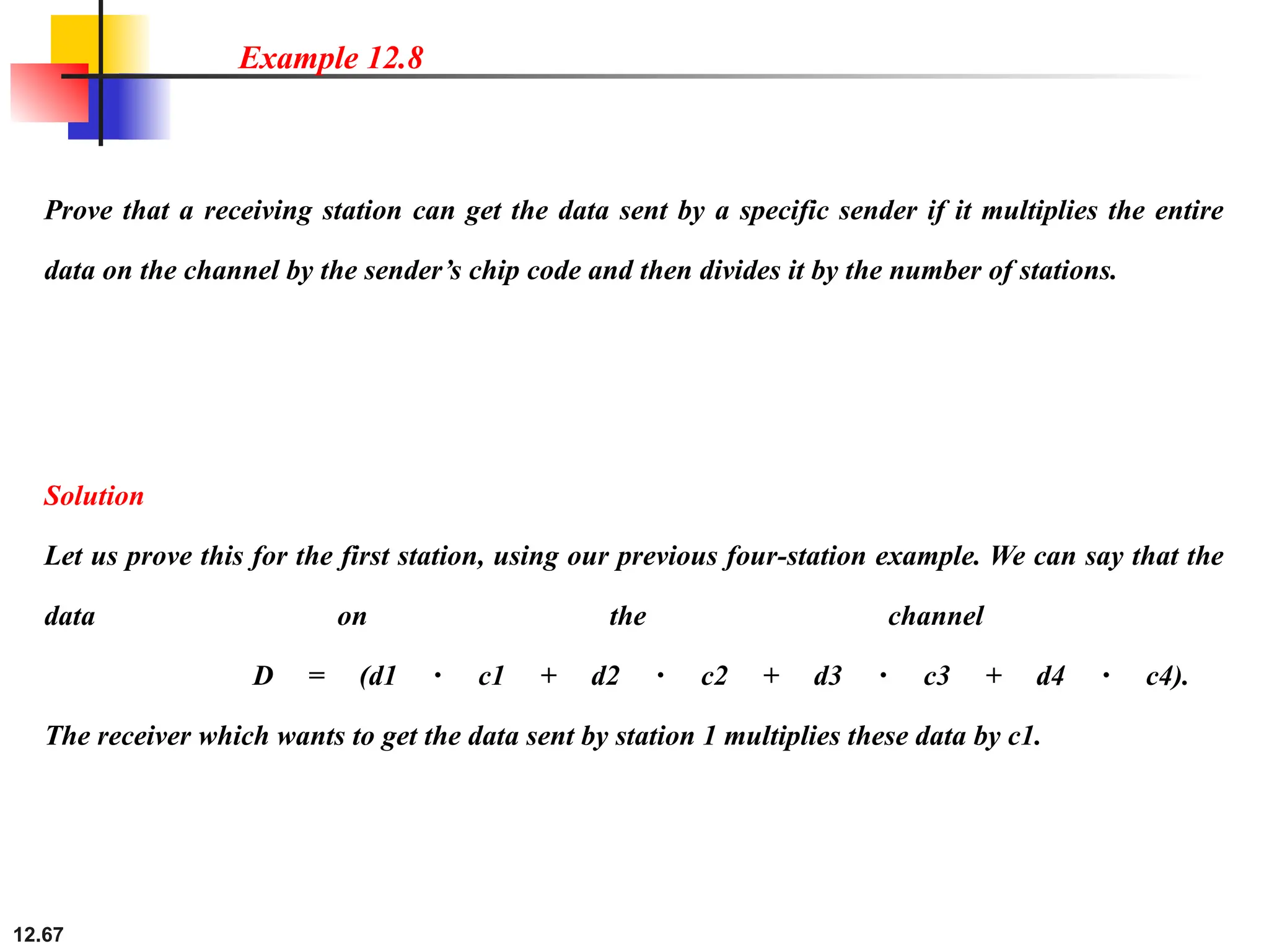
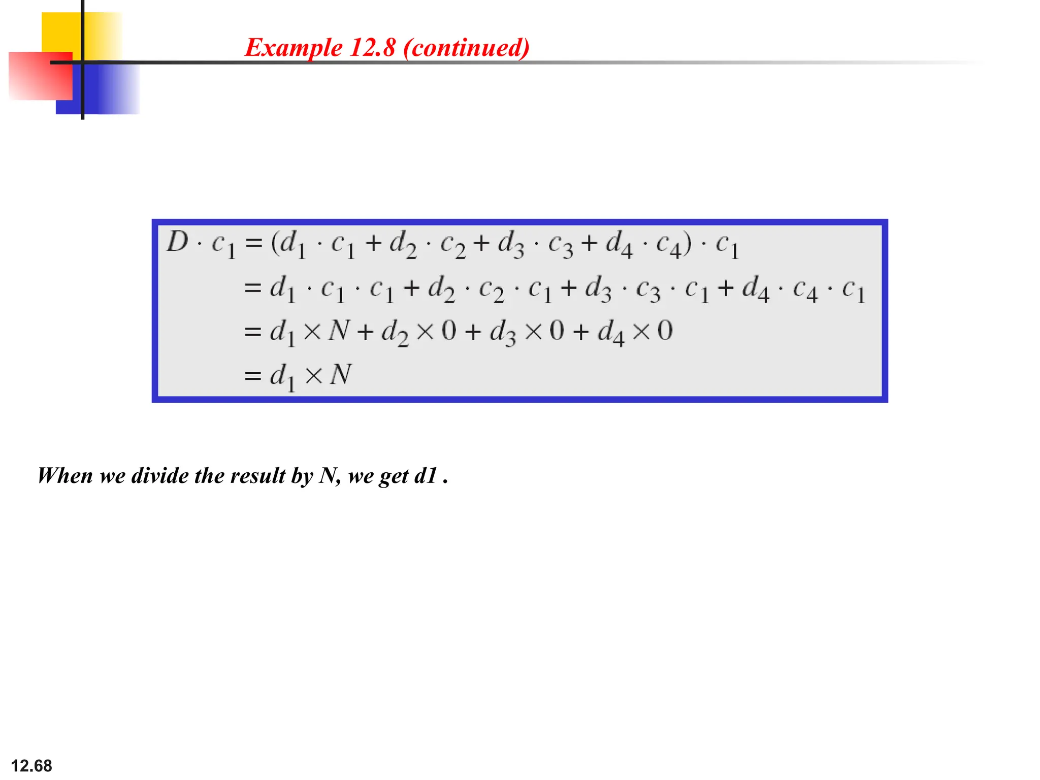
Prove that areceiving station can get the data sent by a specific sender if it multiplies the entire
data on the channel by the sender’s chip code and then divides it by the number of stations.
Example 12.8
Solution
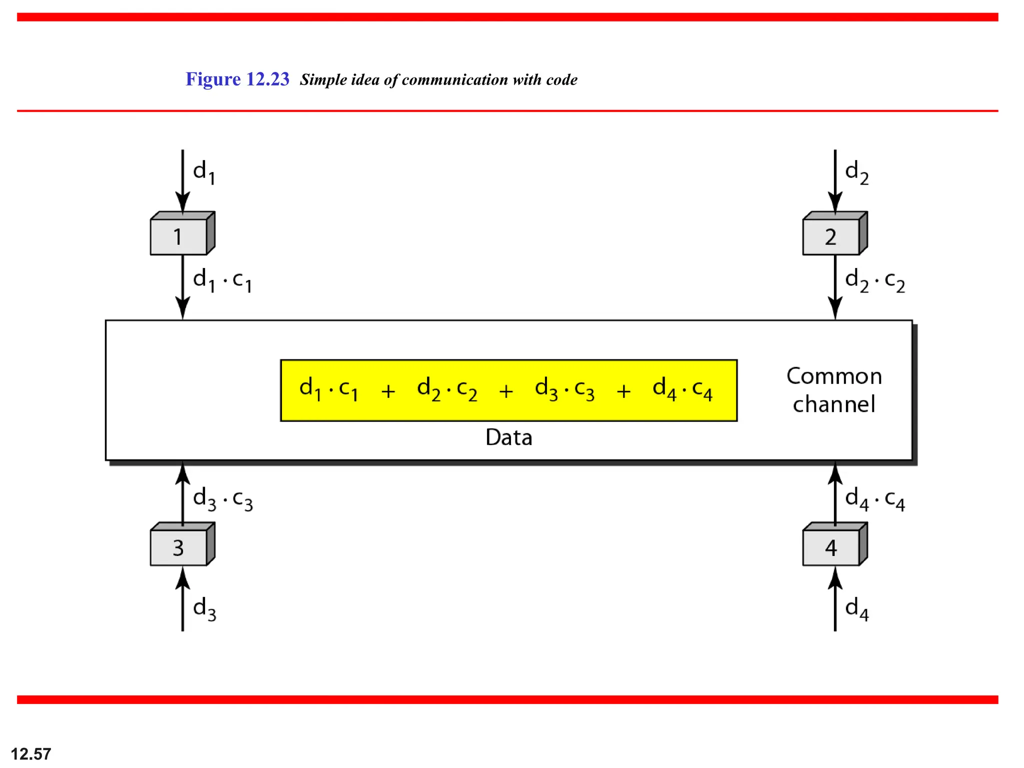
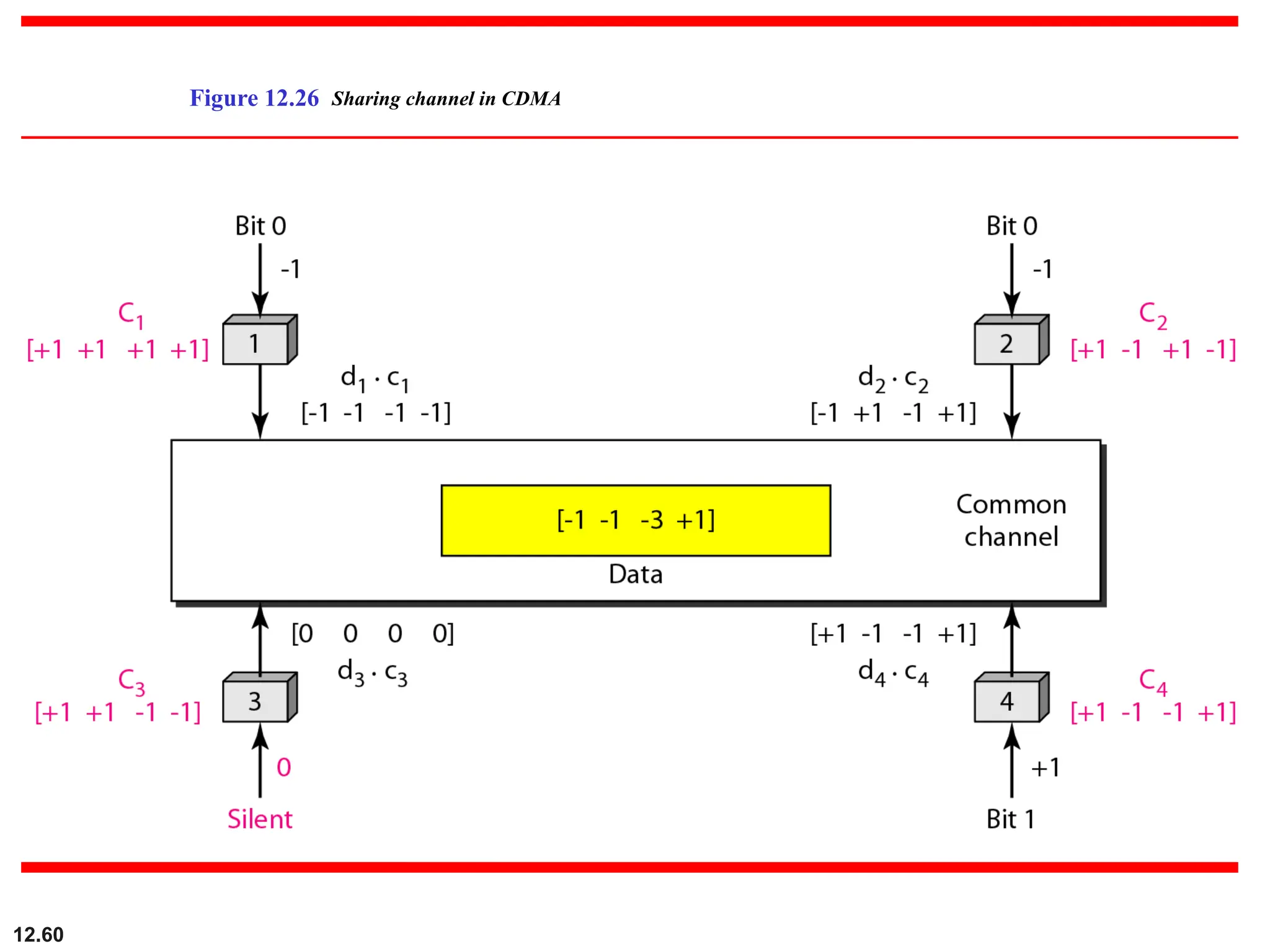
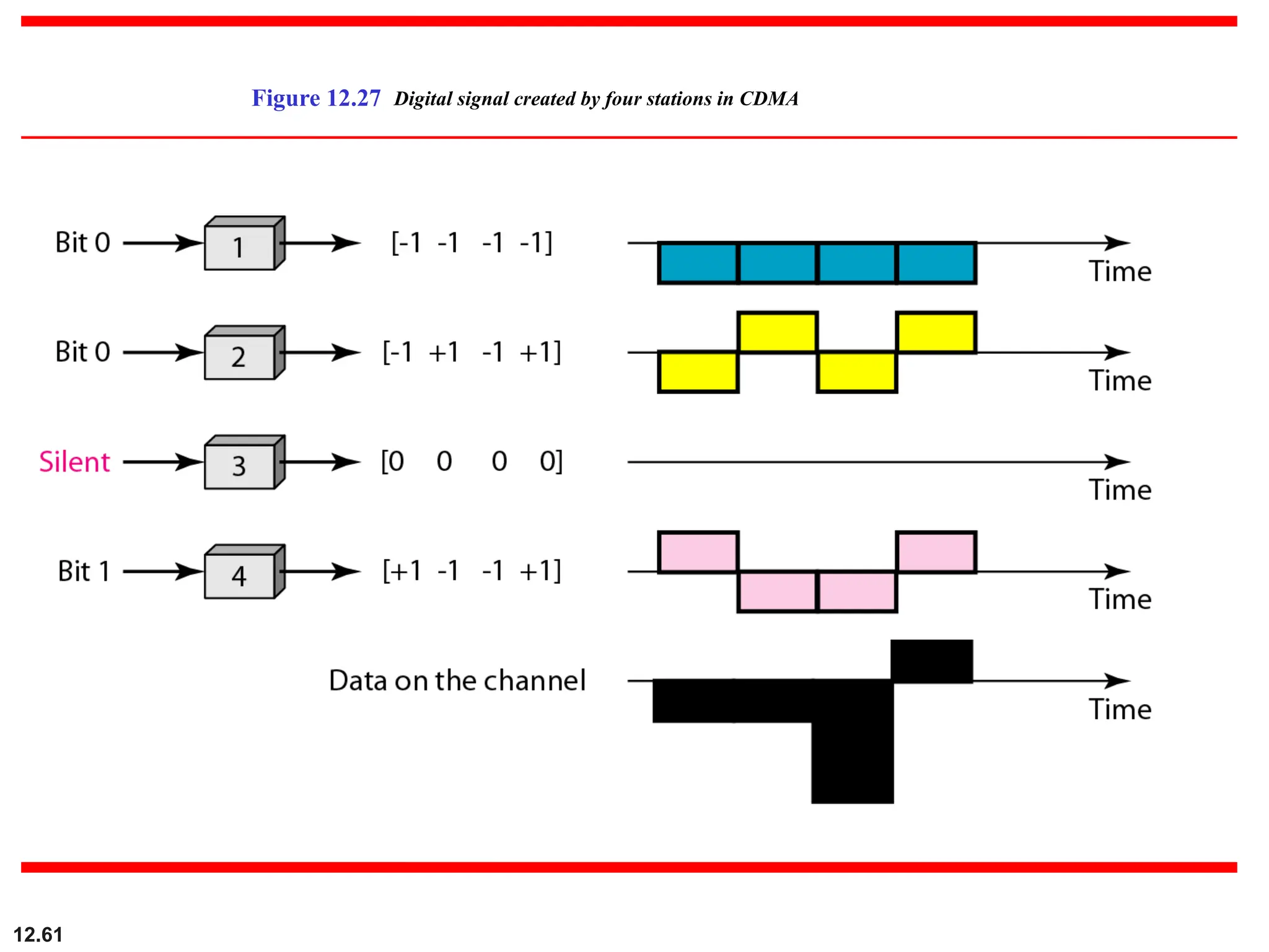
Let us prove this for the first station, using our previous four-station example. We can say that the
data on the channel
D = (d1 c1 + d2 c2 + d3 c3 + d4 c4).
⋅ ⋅ ⋅ ⋅
The receiver which wants to get the data sent by station 1 multiplies these data by c1.

![12.65
Find the chips for a network with
a. Two stations b. Four stations
Example 12.6
Solution
We can use the rows of W2 and W4 in Figure 12.29:
a. For a two-station network, we have
[+1 +1] and [+1 −1].
b. For a four-station network we have
[+1 +1 +1 +1], [+1 −1 +1 −1],
[+1 +1 −1 −1], and [+1 −1 −1 +1].](https://image.slidesharecdn.com/multipleaccess-250828092057-d3243a3c/75/Computer-Networks-Multiple-Access-Protocols-61-2048.jpg)


![12.65
Find the chips for a network with
a. Two stations b. Four stations
Example 12.6
Solution
We can use the rows of W2 and W4 in Figure 12.29:
a. For a two-station network, we have
[+1 +1] and [+1 −1].
b. For a four-station network we have
[+1 +1 +1 +1], [+1 −1 +1 −1],
[+1 +1 −1 −1], and [+1 −1 −1 +1].](https://crownmelresort.com/image.slidesharecdn.com/multipleaccess-250828092057-d3243a3c/75/Computer-Networks-Multiple-Access-Protocols-61-2048.jpg)


![ANPARA THERMAL POWER STATION[1] sangam.pdf](https://cdn.slidesharecdn.com/ss_thumbnails/anparathermalpowerstation1sangam-251121115219-9261cde4-thumbnail.jpg?width=640&height=640&fit=bounds)


