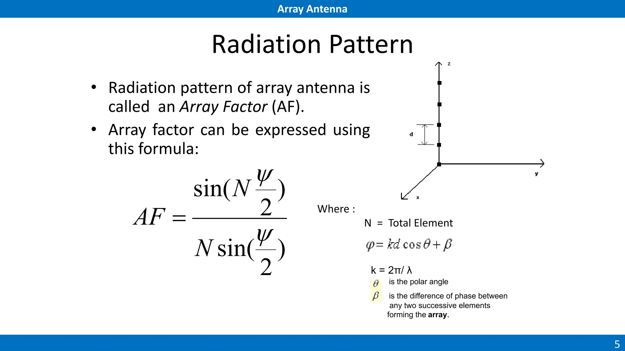
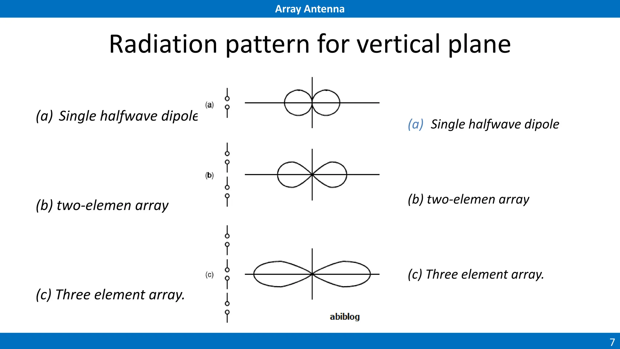
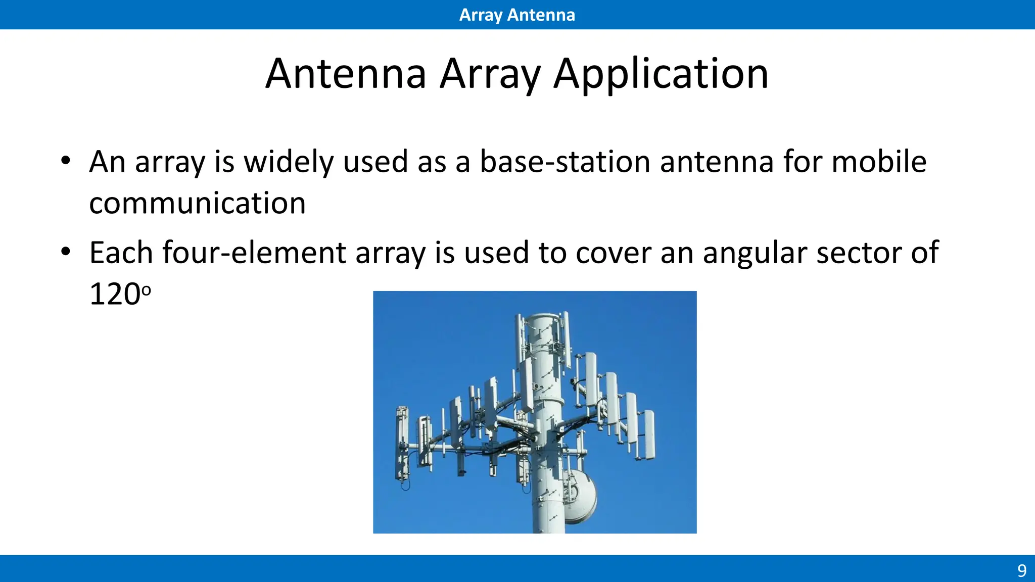
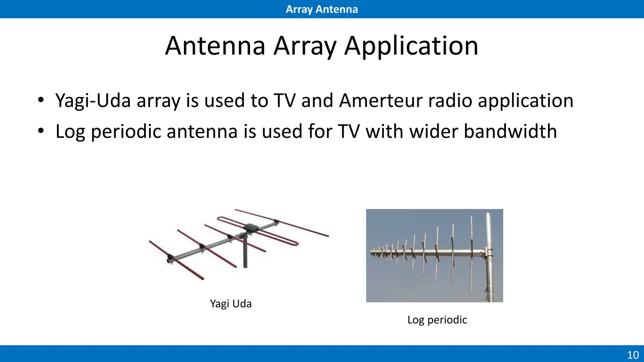
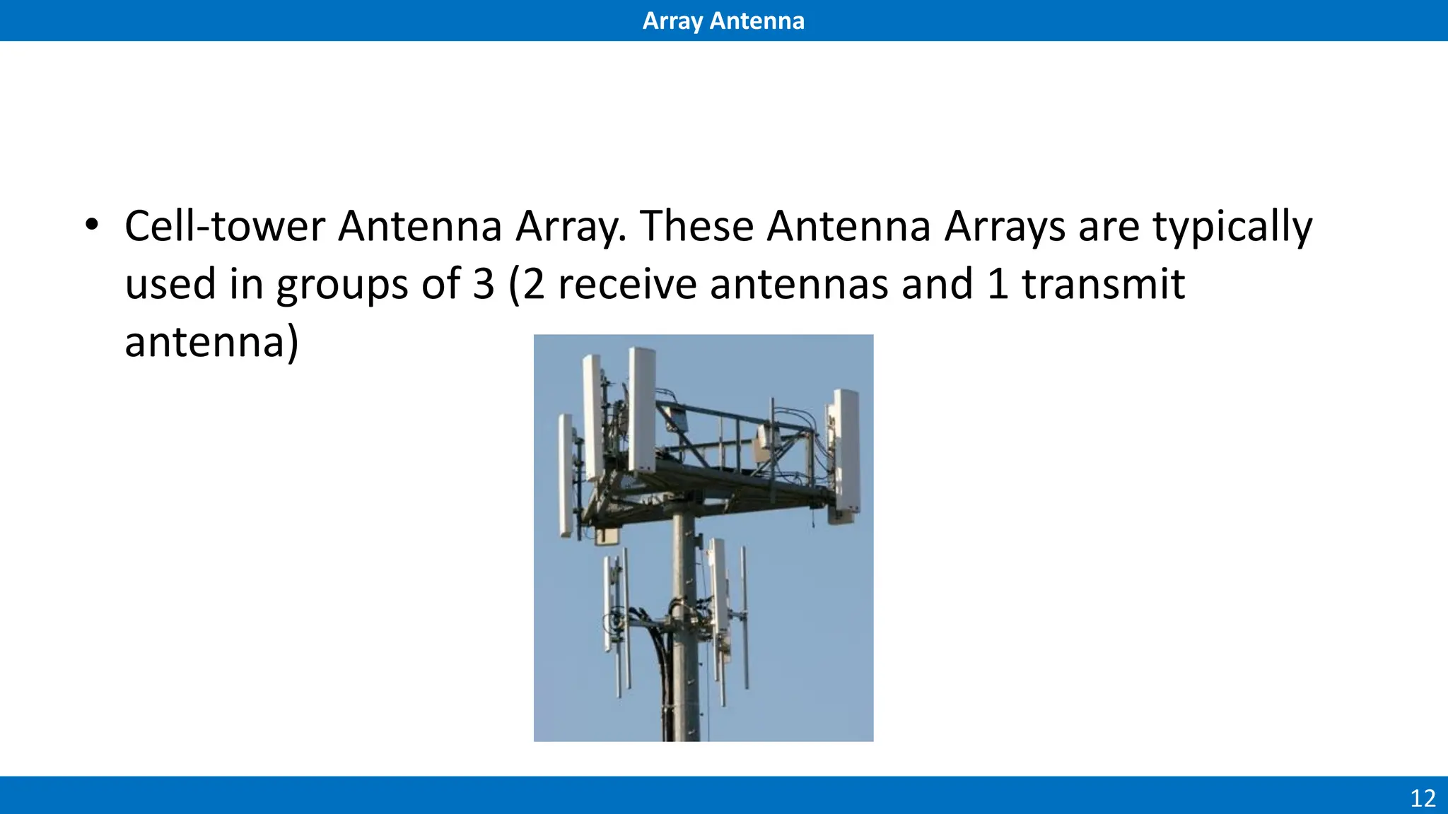
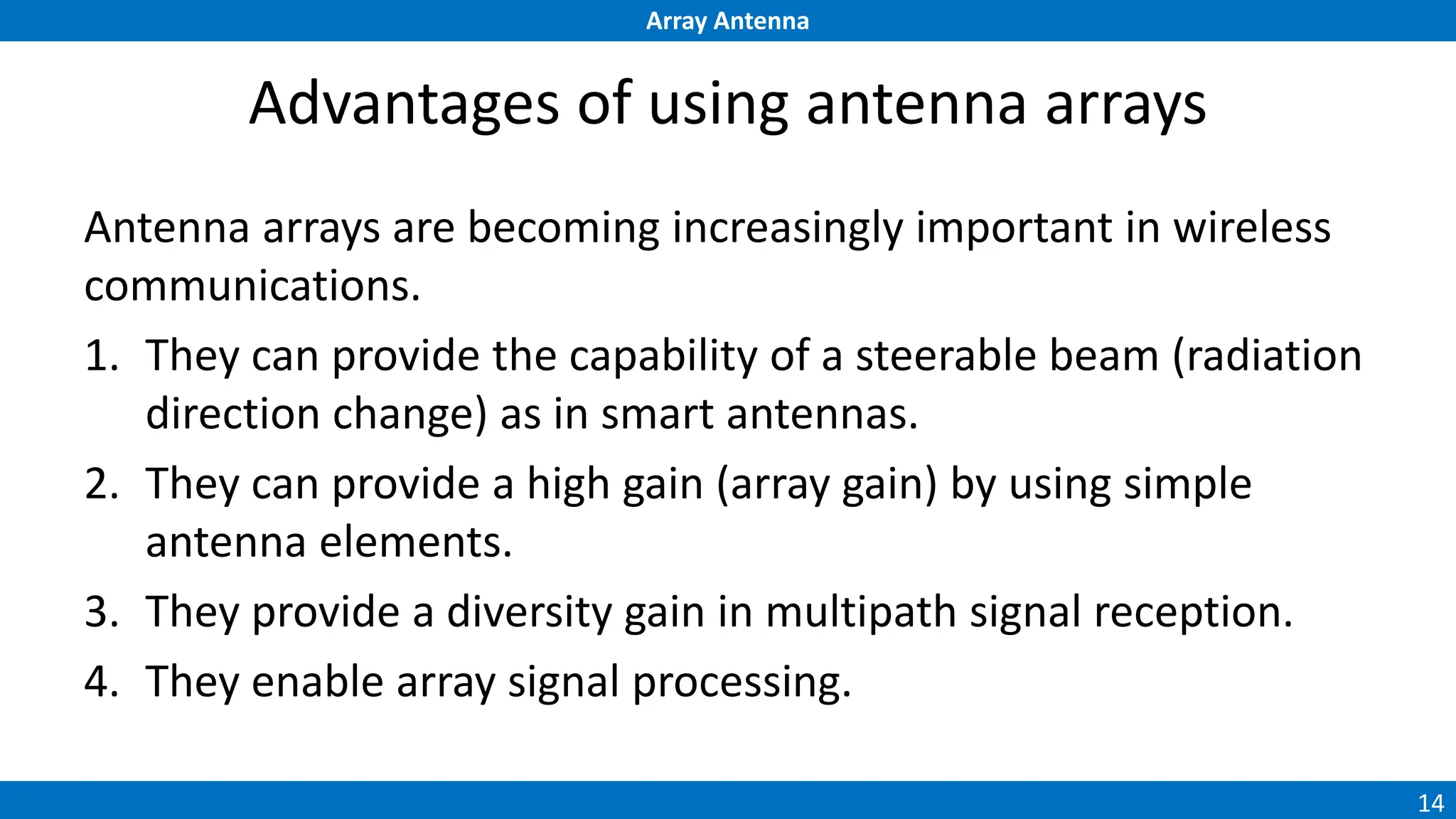
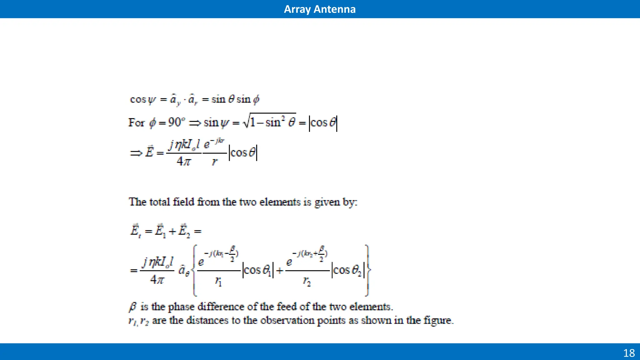
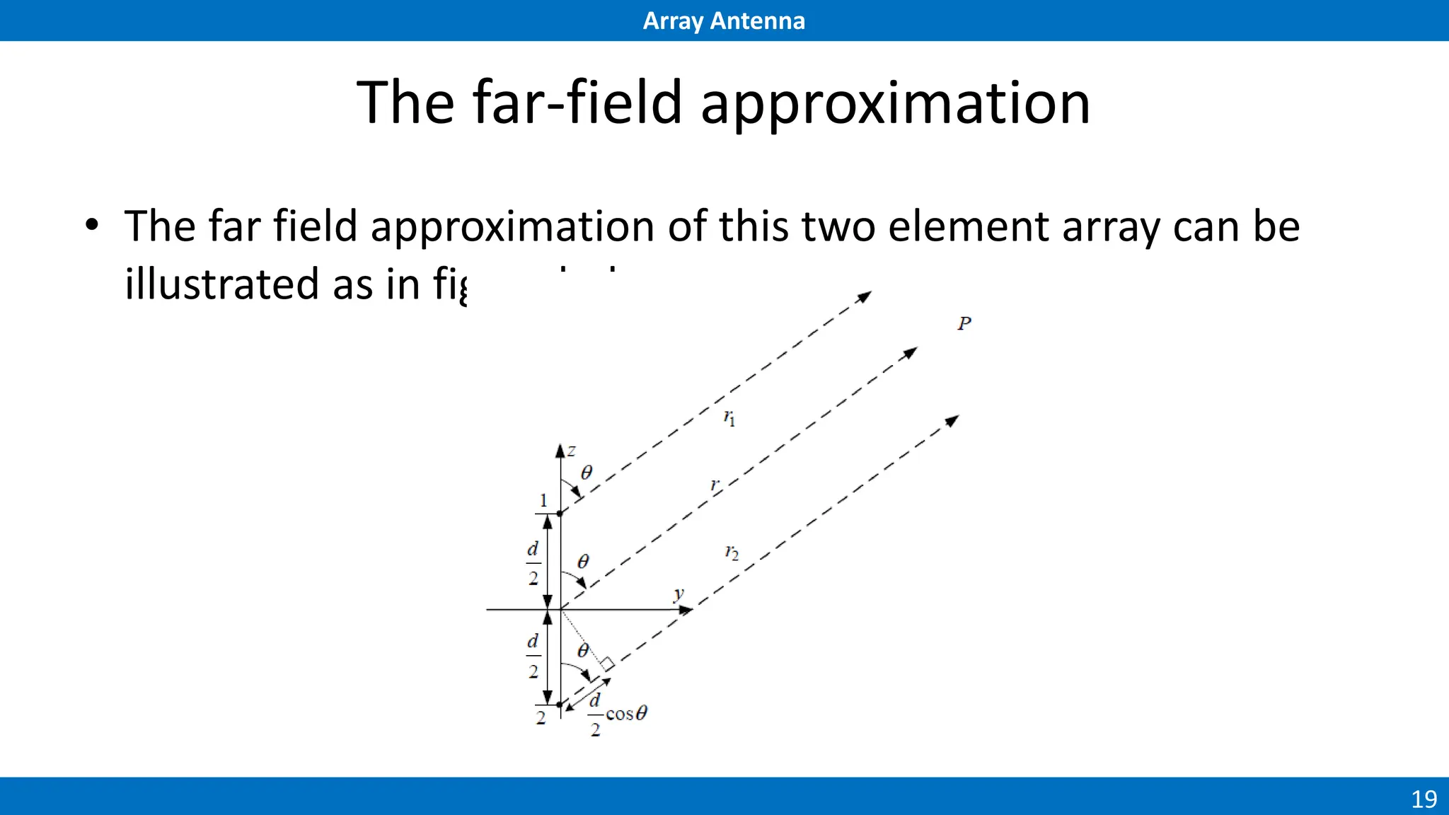
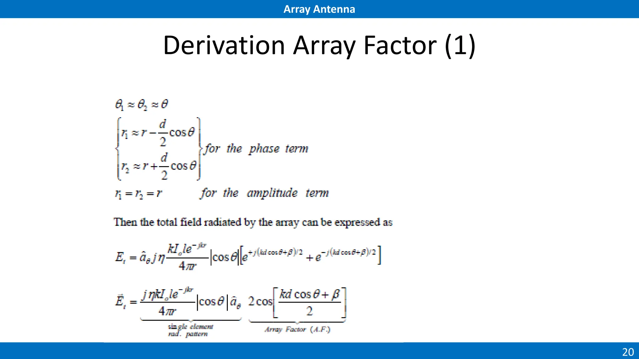
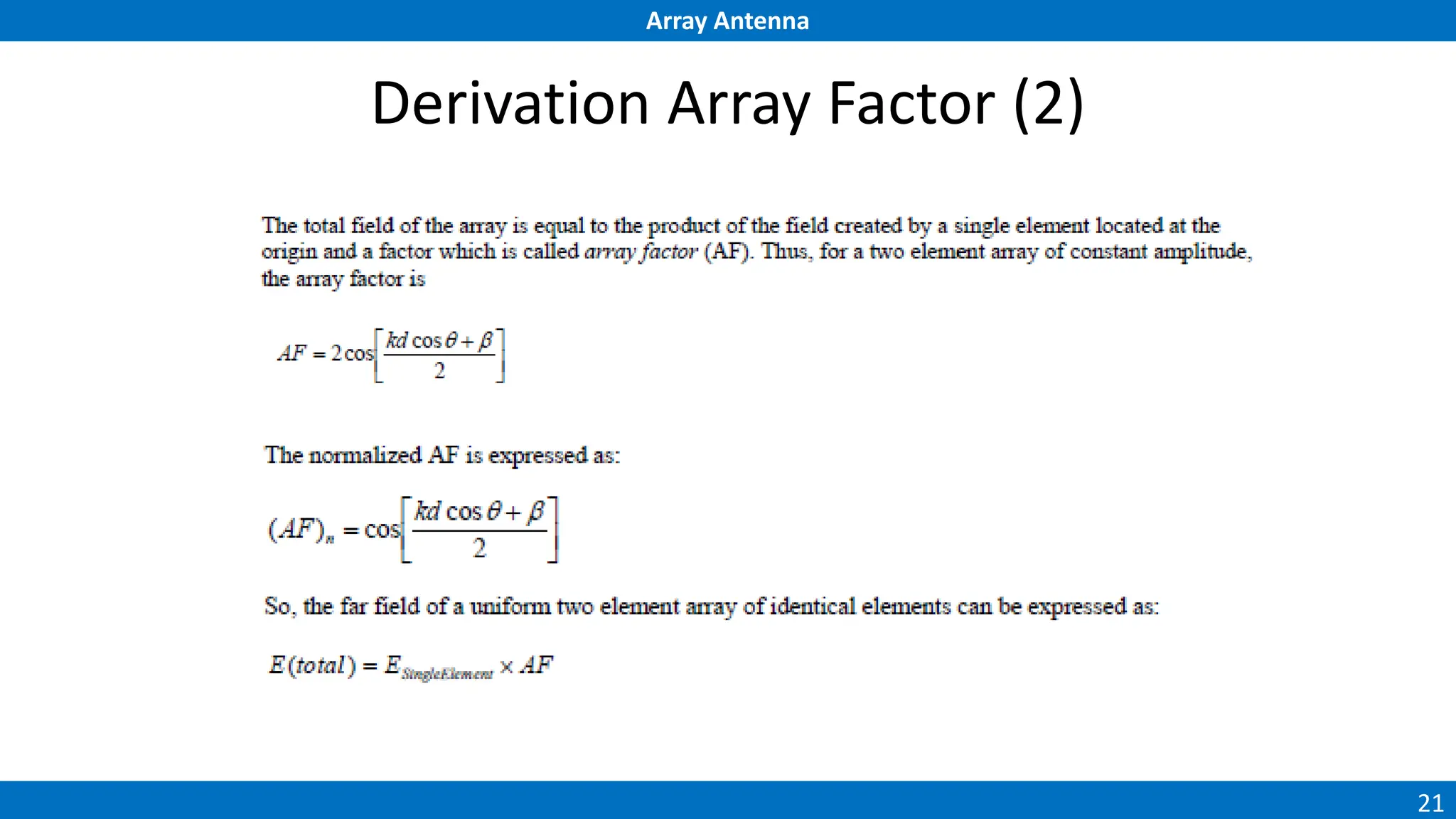
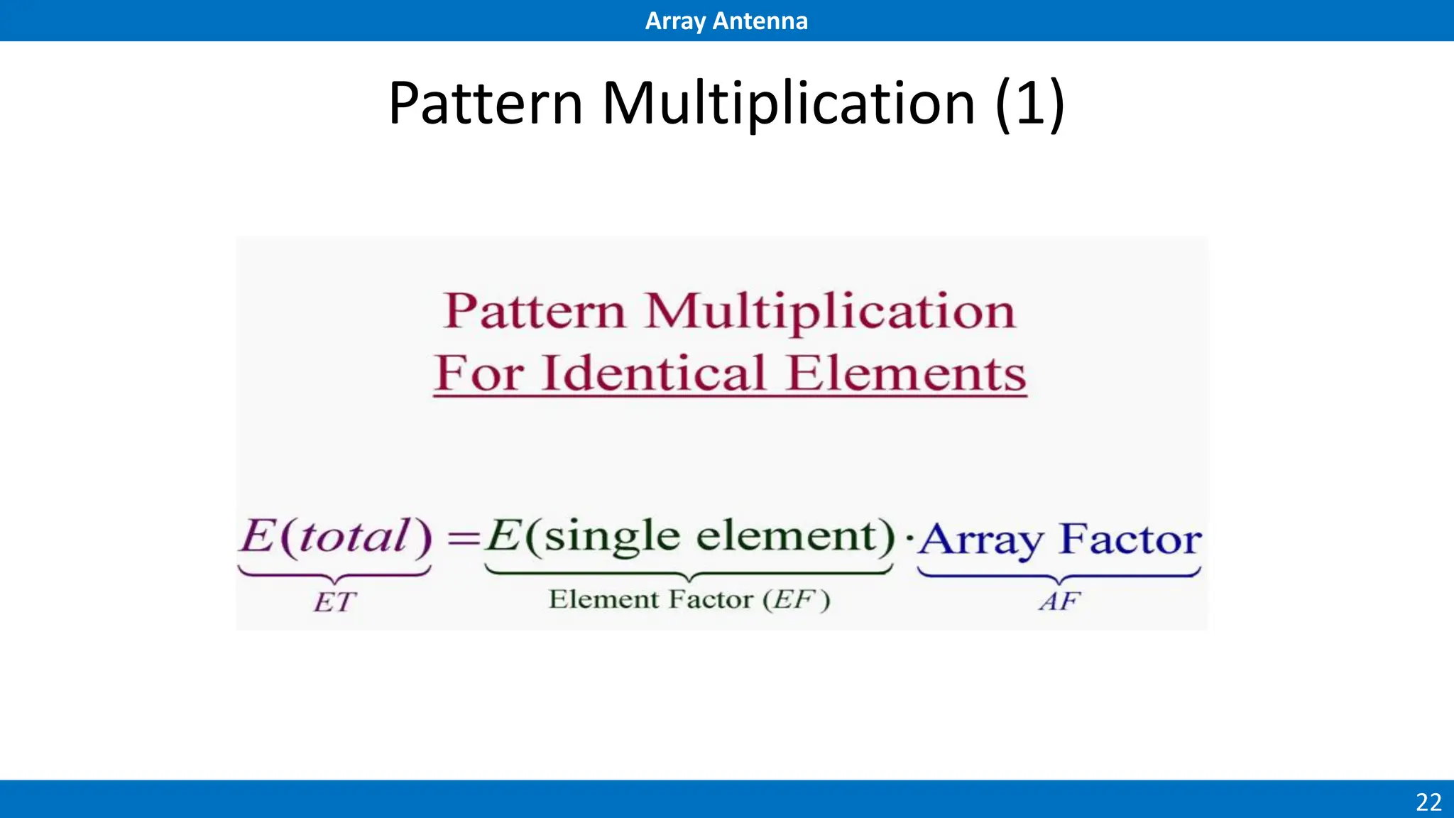
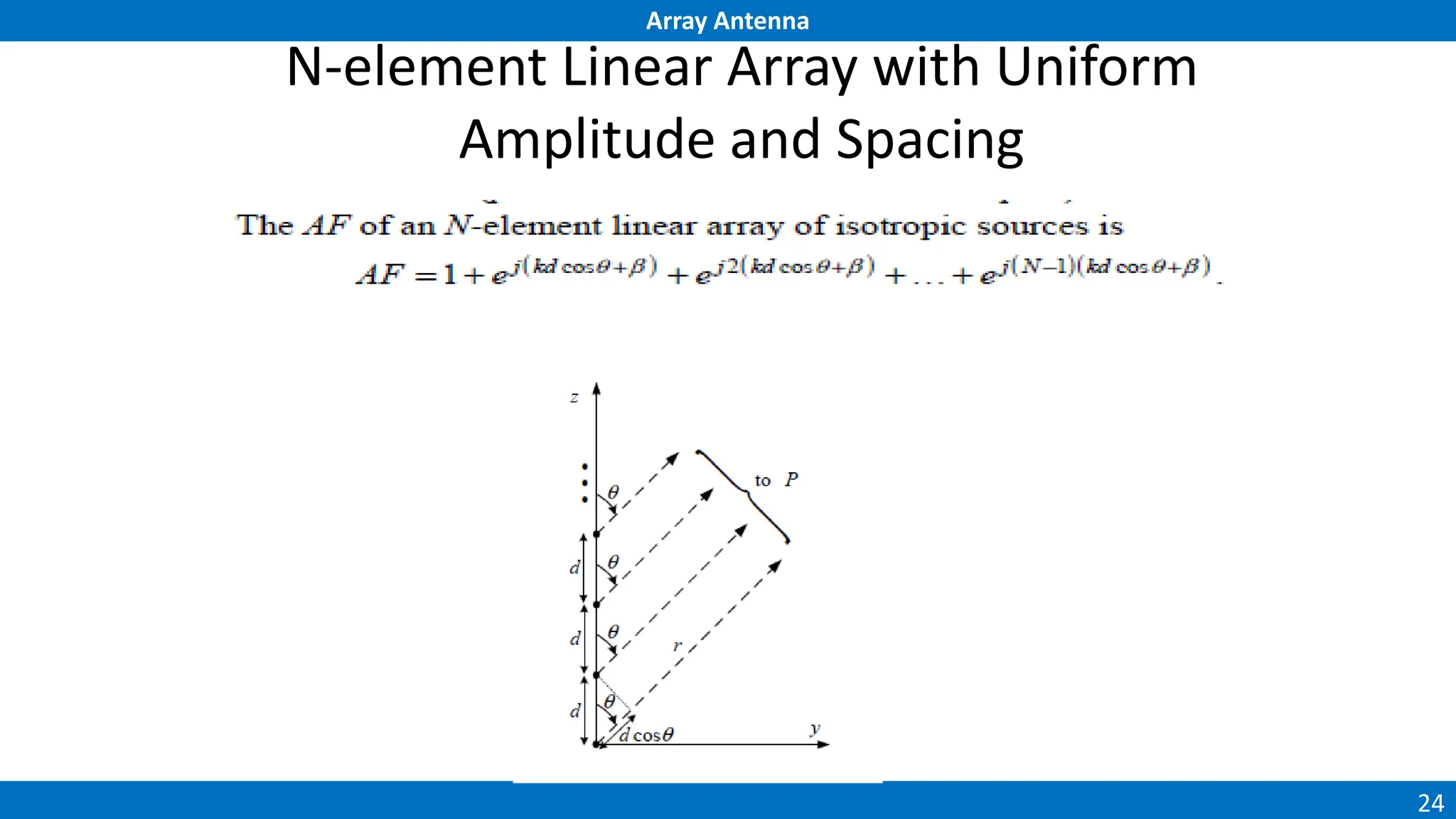
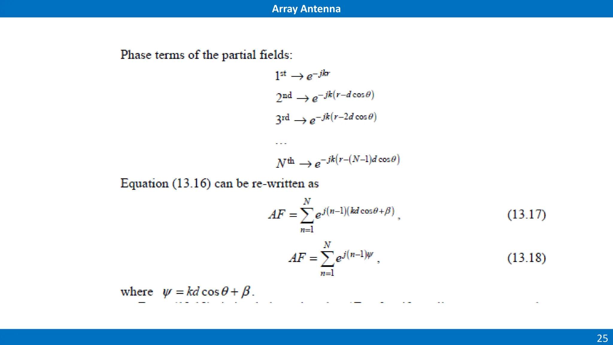
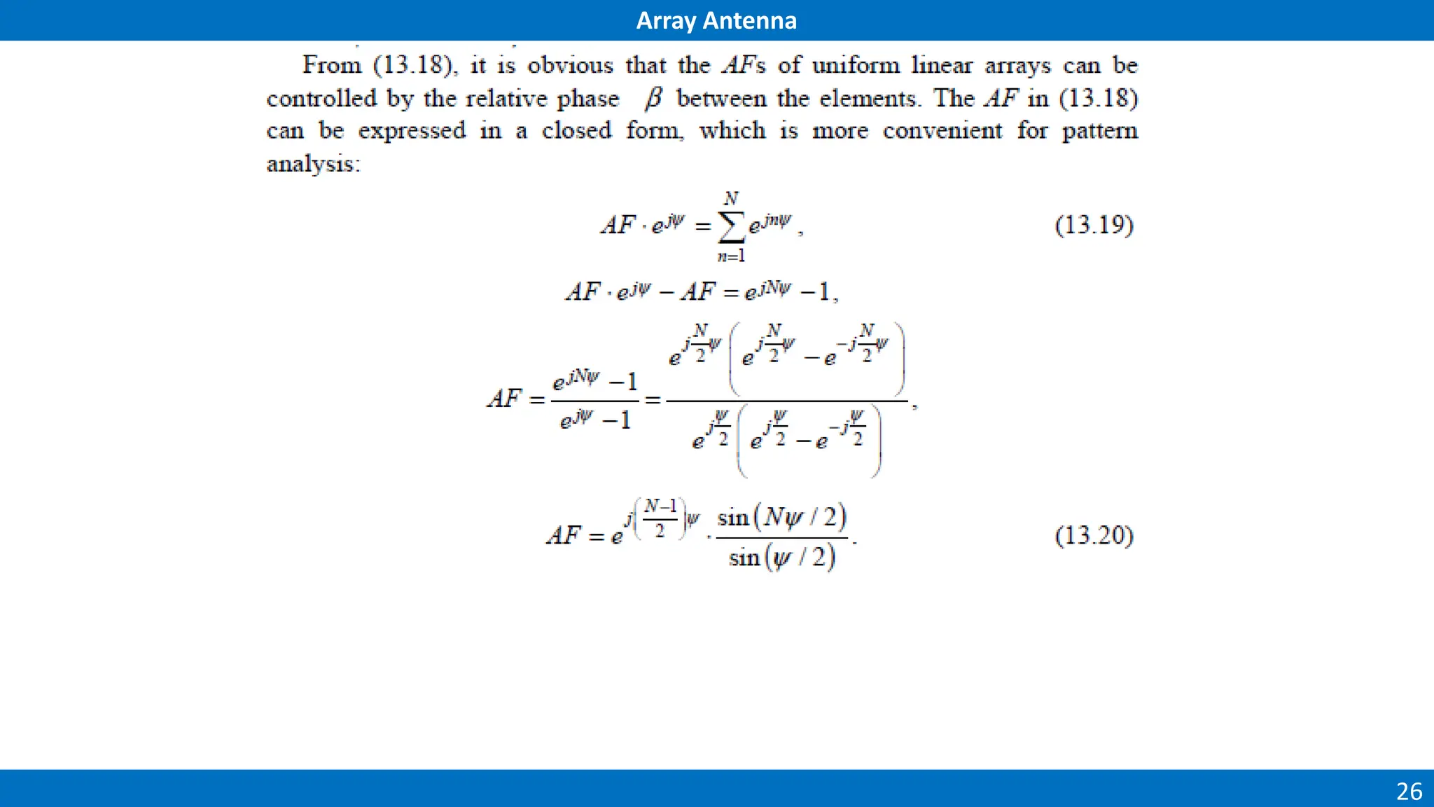
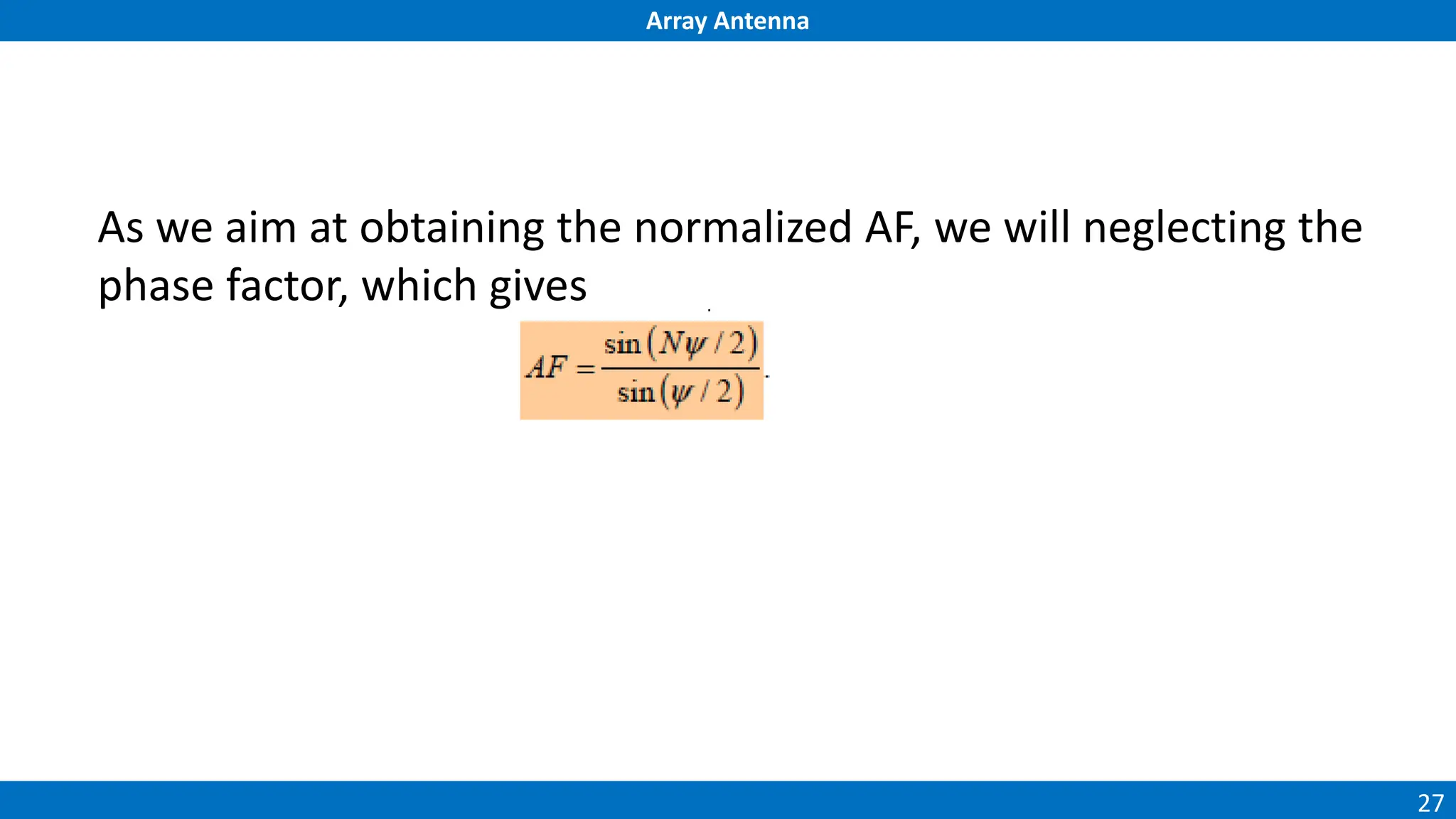
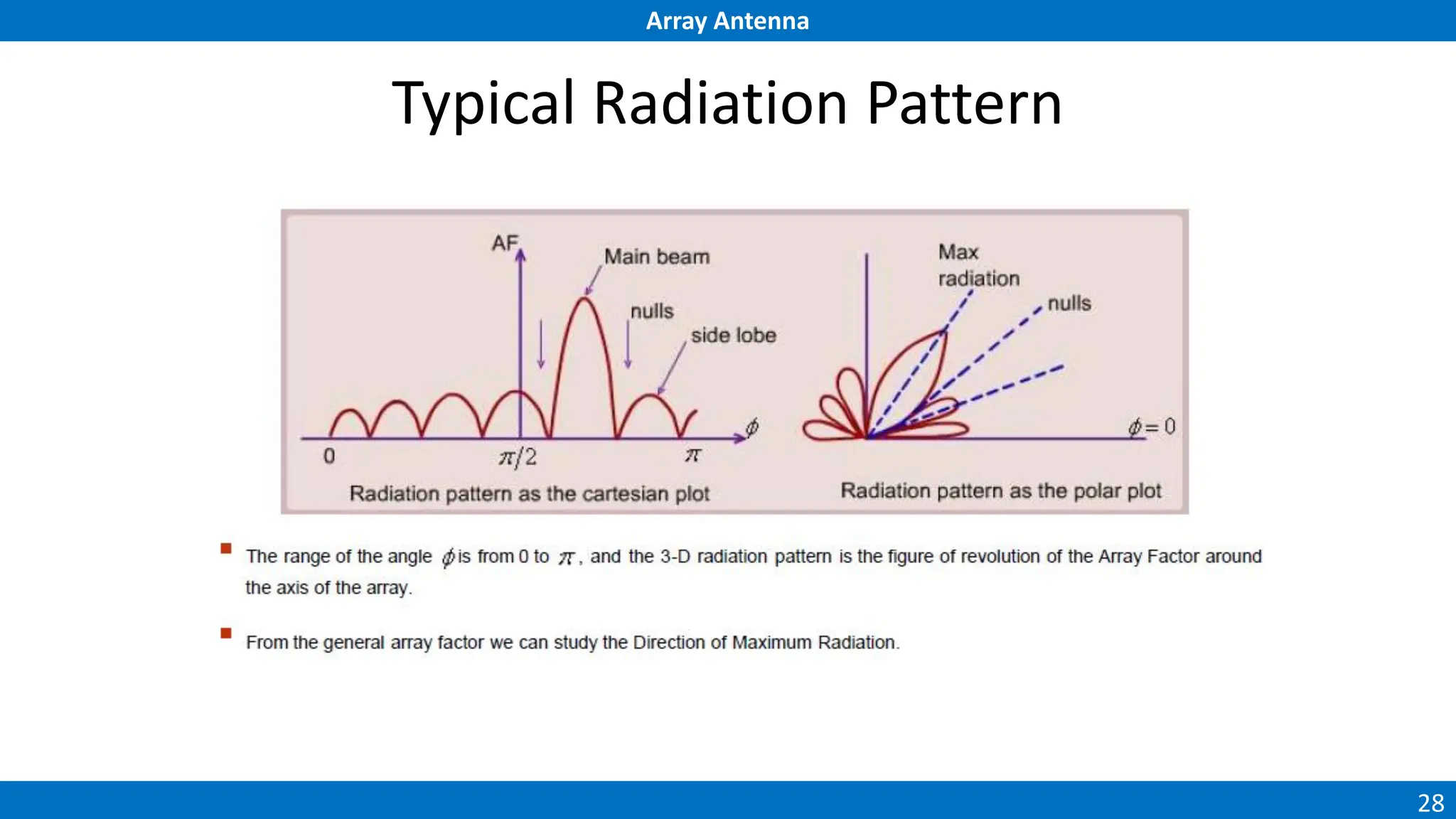
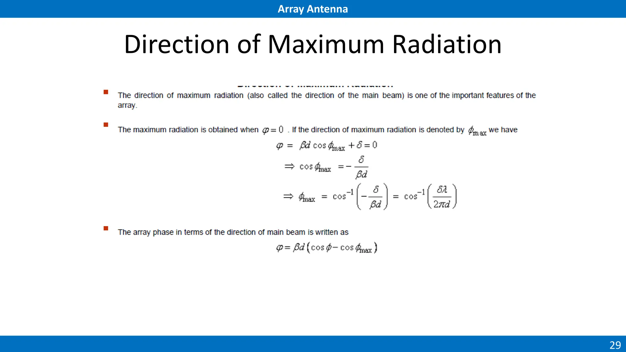
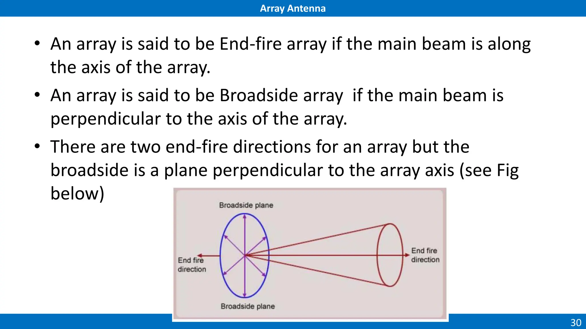
Array Antenna
1
Antenna Array
Chapter 3
Array Antenna
2
Introduction
• Usually the radiation patterns of single-element antennas are
relatively wide. i.e., they have relatively low directivity (gain).
• In long distance communications, antennas with high
directivity are often required. Such antennas are possible to
construct by enlarging the dimensions of the radiating
aperture (maximum size much larger than λ ).
• This approach however may lead to the appearance of multiple
side lobes. Besides, the antenna is usually large and difficult to
fabricate.
Array Antenna
3
Introduction cont.
• Another way to increase the electrical size of an antenna is to
construct it as an assembly of radiating elements in a proper
electrical and geometrical configuration – as known as
antenna array.
• Usually, the array elements are identical.
• This is not necessary but it is practical and simpler for design
and fabrication.
• The individual elements may be of any type (wire dipoles,
loops, apertures, etc.)
Array Antenna
4
Five basic methods
• To control the overall antenna pattern:
a) the geometrical configuration of the overall array (linear, circular,
spherical, rectangular, etc.)
b) the relative placement of the elements.
c) the excitation amplitude of the individual elements.
d) the excitation phase of each element.
e) the individual pattern of each element.
Array Antenna
5
Radiation Pattern
• Radiation pattern of array antenna is
called an Array Factor (AF).
• Array factor can be expressed using
this formula:
)
2
sin(
)
2
sin(


N
N
AF = Where :
N = Total Element
k = 2π/ λ
is the polar angle
is the difference of phase between
any two successive elements
forming the array.
Array Antenna
6
Array Antenna
• At the end of the chapter, you should able:
– What is the array antenna application
– What is array factor and how to determine it
– What is the radiation pattern for array antenna look like
Array Antenna
7
Radiation pattern for vertical plane
(a) Single halfwave dipole
(b) two-elemen array
(c) Three element array.
(a) Single halfwave dipole
(b) two-elemen array
(c) Three element array.
Array Antenna
8
Why An Array of Antenna?
• Single element is relatively wide and low gain (directivity)
• To have very high gain and long distance antenna, this can be accomplished
by increasing the electrical size of the antenna
• Enlarge dimensions of the antenna without increasing the size of individual
elements is to form an assembly of radiating elements in an electrical and
geometrical configuration
• This new antenna, formed by multielements, is referred to as an array
• Most cases, the elements of an array are identical
• The total field is determined by the vector addition of the fields radiated by
the individual elements
Array Antenna
9
Antenna Array Application
• An array is widely used as a base-station antenna for mobile
communication
• Each four-element array is used to cover an angular sector of
120o
Array Antenna
10
Antenna Array Application
• Yagi-Uda array is used to TV and Amerteur radio application
• Log periodic antenna is used for TV with wider bandwidth
Yagi Uda
Log periodic
Array Antenna
11
Examples of antenna arrays
• Four-element microstrip antenna array (phased array).
Array Antenna
12
• Cell-tower Antenna Array. These Antenna Arrays are typically
used in groups of 3 (2 receive antennas and 1 transmit
antenna)
Array Antenna
13
Array Theory
• Configuration of individual radiating elements that are
arranged in space and can be used to produce a directional
radiation pattern
• Allows shaping of radiation pattern
– Narrow beam
– Low sidelobe
– Higher gain & directivity
• Arrays usually employ identical antenna elements
Array Antenna
14
Advantages of using antenna arrays
Antenna arrays are becoming increasingly important in wireless
communications.
1. They can provide the capability of a steerable beam (radiation
direction change) as in smart antennas.
2. They can provide a high gain (array gain) by using simple
antenna elements.
3. They provide a diversity gain in multipath signal reception.
4. They enable array signal processing.
Array Antenna
15
Far-Field Expression of An Antenna Array
Array Antenna
16
Uniform Liner Arrays (ULAs)
Array Antenna
17
Two element array
• Let us assume, that two infinitesimal horizontal dipole antennas positioned along the z-axis as depict
in figure below.
• The total field of the array is determined by the vector addition of the fields radiated by the
individual elements.
• The electric field pattern in the y-z plane for one element is given by:
Array Antenna
18
Array Antenna
19
The far-field approximation
• The far field approximation of this two element array can be
illustrated as in figure below:
Array Antenna
20
Derivation Array Factor (1)
Array Antenna
21
Derivation Array Factor (2)
Array Antenna
22
Pattern Multiplication (1)
Array Antenna
23
Pattern Multiplication (2)
• The concept of pattern multiplication valid for arrays with any
number of identical elements.
• So each array has its own array factor (AF).
• The total pattern, therefore, can be controlled via the single-
element pattern or via the AF of an array can be obtained by
replacing the actual elements with isotropic sources.
• The AF, in general, depends on:
– Number of elements.
– Relative excitation (magnitudes and phases).
– Spacing between the elements.
Array Antenna
24
N-element Linear Array with Uniform
Amplitude and Spacing
Array Antenna
25
Array Antenna
26
Array Antenna
27
As we aim at obtaining the normalized AF, we will neglecting the
phase factor, which gives
Array Antenna
28
Typical Radiation Pattern
Array Antenna
29
Direction of Maximum Radiation
Array Antenna
30
• An array is said to be End-fire array if the main beam is along
the axis of the array.
• An array is said to be Broadside array if the main beam is
perpendicular to the axis of the array.
• There are two end-fire directions for an array but the
broadside is a plane perpendicular to the array axis (see Fig
below)
Array Antenna
31
Directions of Nulls
Array Antenna
32
Terminology
Antenna – structure or device used to collect or radiate electromagnetic waves
Array – assembly of antenna elements with dimensions, spacing, and illumination sequence such that the
fields of the individual elements combine to produce a maximum intensity in a particular direction
and minimum intensities in other directions
Beamwidth – the angle between the half-power (3-dB) points of the main lobe, when referenced to the peak
effective radiated power of the main lobe
Directivity – the ratio of the radiation intensity in a given direction from the antenna to the radiation intensity
averaged over all directions
Effective area – the functional equivalent area from which an antenna directed toward the source of the
received signal gathers or absorbs the energy of an incident electromagnetic wave
Efficiency – ratio of the total radiated power to the total input power
Far field – region where wavefront is considered planar
Gain – ratio of the power at the input of a loss-free isotropic antenna to the power supplied to the input of
the given antenna to produce, in a given direction, the same field strength at the same distance
Isotropic – radiates equally in all directions
Main lobe – the lobe containing the maximum power
Null – a zone in which the effective radiated power is at a minimum relative to the maximum effective
radiation power of the main lobe
Radiation pattern – variation of the field intensity of an antenna as an angular function with respect to the axis
Radiation resistance – resistance that, if inserted in place of the antenna, would consume that same amount of
power that is radiated by the antenna
Side lobe – a lobe in any direction other than the main lobe
Array Antenna
33
Tutorial for Array Antenna (1)
A three elements array of isotropic sources has the phase and
the magnitude relationship as shown in figure below. The
spacing between the elements is d =
λ
2
.
(i) Find the array factor
(ii) Find the nulls
z
y
-1
-j
+1
#2
#1
#3
d
d
Array Antenna
34
Tutorial for Array Antenna (2)
four isotropic sources with spacing d between them are placed
along the z-axis as shown in figure below. Assuming that the
amplitudes of elements #1 and #2 are +1 and the amplitudes of
elements #3 and #4 are -1, find the,
(i) The array factor.
(ii) The nulls when d= λ/2
#4
y
-1
-j
+1
#2
#1
#3
d
d
-j
z
d/2
d/2

Antenna Array Tutorial for dummies making of.pdf

  • 1.
  • 2.
    Array Antenna 2 Introduction • Usuallythe radiation patterns of single-element antennas are relatively wide. i.e., they have relatively low directivity (gain). • In long distance communications, antennas with high directivity are often required. Such antennas are possible to construct by enlarging the dimensions of the radiating aperture (maximum size much larger than λ ). • This approach however may lead to the appearance of multiple side lobes. Besides, the antenna is usually large and difficult to fabricate.
  • 3.
    Array Antenna 3 Introduction cont. •Another way to increase the electrical size of an antenna is to construct it as an assembly of radiating elements in a proper electrical and geometrical configuration – as known as antenna array. • Usually, the array elements are identical. • This is not necessary but it is practical and simpler for design and fabrication. • The individual elements may be of any type (wire dipoles, loops, apertures, etc.)
  • 4.
    Array Antenna 4 Five basicmethods • To control the overall antenna pattern: a) the geometrical configuration of the overall array (linear, circular, spherical, rectangular, etc.) b) the relative placement of the elements. c) the excitation amplitude of the individual elements. d) the excitation phase of each element. e) the individual pattern of each element.
  • 5.
    Array Antenna 5 Radiation Pattern •Radiation pattern of array antenna is called an Array Factor (AF). • Array factor can be expressed using this formula: ) 2 sin( ) 2 sin(   N N AF = Where : N = Total Element k = 2π/ λ is the polar angle is the difference of phase between any two successive elements forming the array.
  • 6.
    Array Antenna 6 Array Antenna •At the end of the chapter, you should able: – What is the array antenna application – What is array factor and how to determine it – What is the radiation pattern for array antenna look like
  • 7.
    Array Antenna 7 Radiation patternfor vertical plane (a) Single halfwave dipole (b) two-elemen array (c) Three element array. (a) Single halfwave dipole (b) two-elemen array (c) Three element array.
  • 8.
    Array Antenna 8 Why AnArray of Antenna? • Single element is relatively wide and low gain (directivity) • To have very high gain and long distance antenna, this can be accomplished by increasing the electrical size of the antenna • Enlarge dimensions of the antenna without increasing the size of individual elements is to form an assembly of radiating elements in an electrical and geometrical configuration • This new antenna, formed by multielements, is referred to as an array • Most cases, the elements of an array are identical • The total field is determined by the vector addition of the fields radiated by the individual elements
  • 9.
    Array Antenna 9 Antenna ArrayApplication • An array is widely used as a base-station antenna for mobile communication • Each four-element array is used to cover an angular sector of 120o
  • 10.
    Array Antenna 10 Antenna ArrayApplication • Yagi-Uda array is used to TV and Amerteur radio application • Log periodic antenna is used for TV with wider bandwidth Yagi Uda Log periodic
  • 11.
    Array Antenna 11 Examples ofantenna arrays • Four-element microstrip antenna array (phased array).
  • 12.
    Array Antenna 12 • Cell-towerAntenna Array. These Antenna Arrays are typically used in groups of 3 (2 receive antennas and 1 transmit antenna)
  • 13.
    Array Antenna 13 Array Theory •Configuration of individual radiating elements that are arranged in space and can be used to produce a directional radiation pattern • Allows shaping of radiation pattern – Narrow beam – Low sidelobe – Higher gain & directivity • Arrays usually employ identical antenna elements
  • 14.
    Array Antenna 14 Advantages ofusing antenna arrays Antenna arrays are becoming increasingly important in wireless communications. 1. They can provide the capability of a steerable beam (radiation direction change) as in smart antennas. 2. They can provide a high gain (array gain) by using simple antenna elements. 3. They provide a diversity gain in multipath signal reception. 4. They enable array signal processing.
  • 15.
  • 16.
  • 17.
    Array Antenna 17 Two elementarray • Let us assume, that two infinitesimal horizontal dipole antennas positioned along the z-axis as depict in figure below. • The total field of the array is determined by the vector addition of the fields radiated by the individual elements. • The electric field pattern in the y-z plane for one element is given by:
  • 18.
  • 19.
    Array Antenna 19 The far-fieldapproximation • The far field approximation of this two element array can be illustrated as in figure below:
  • 20.
  • 21.
  • 22.
  • 23.
    Array Antenna 23 Pattern Multiplication(2) • The concept of pattern multiplication valid for arrays with any number of identical elements. • So each array has its own array factor (AF). • The total pattern, therefore, can be controlled via the single- element pattern or via the AF of an array can be obtained by replacing the actual elements with isotropic sources. • The AF, in general, depends on: – Number of elements. – Relative excitation (magnitudes and phases). – Spacing between the elements.
  • 24.
    Array Antenna 24 N-element LinearArray with Uniform Amplitude and Spacing
  • 25.
  • 26.
  • 27.
    Array Antenna 27 As weaim at obtaining the normalized AF, we will neglecting the phase factor, which gives
  • 28.
  • 29.
  • 30.
    Array Antenna 30 • Anarray is said to be End-fire array if the main beam is along the axis of the array. • An array is said to be Broadside array if the main beam is perpendicular to the axis of the array. • There are two end-fire directions for an array but the broadside is a plane perpendicular to the array axis (see Fig below)
  • 31.
  • 32.
    Array Antenna 32 Terminology Antenna –structure or device used to collect or radiate electromagnetic waves Array – assembly of antenna elements with dimensions, spacing, and illumination sequence such that the fields of the individual elements combine to produce a maximum intensity in a particular direction and minimum intensities in other directions Beamwidth – the angle between the half-power (3-dB) points of the main lobe, when referenced to the peak effective radiated power of the main lobe Directivity – the ratio of the radiation intensity in a given direction from the antenna to the radiation intensity averaged over all directions Effective area – the functional equivalent area from which an antenna directed toward the source of the received signal gathers or absorbs the energy of an incident electromagnetic wave Efficiency – ratio of the total radiated power to the total input power Far field – region where wavefront is considered planar Gain – ratio of the power at the input of a loss-free isotropic antenna to the power supplied to the input of the given antenna to produce, in a given direction, the same field strength at the same distance Isotropic – radiates equally in all directions Main lobe – the lobe containing the maximum power Null – a zone in which the effective radiated power is at a minimum relative to the maximum effective radiation power of the main lobe Radiation pattern – variation of the field intensity of an antenna as an angular function with respect to the axis Radiation resistance – resistance that, if inserted in place of the antenna, would consume that same amount of power that is radiated by the antenna Side lobe – a lobe in any direction other than the main lobe
  • 33.
    Array Antenna 33 Tutorial forArray Antenna (1) A three elements array of isotropic sources has the phase and the magnitude relationship as shown in figure below. The spacing between the elements is d = λ 2 . (i) Find the array factor (ii) Find the nulls z y -1 -j +1 #2 #1 #3 d d
  • 34.
    Array Antenna 34 Tutorial forArray Antenna (2) four isotropic sources with spacing d between them are placed along the z-axis as shown in figure below. Assuming that the amplitudes of elements #1 and #2 are +1 and the amplitudes of elements #3 and #4 are -1, find the, (i) The array factor. (ii) The nulls when d= λ/2 #4 y -1 -j +1 #2 #1 #3 d d -j z d/2 d/2