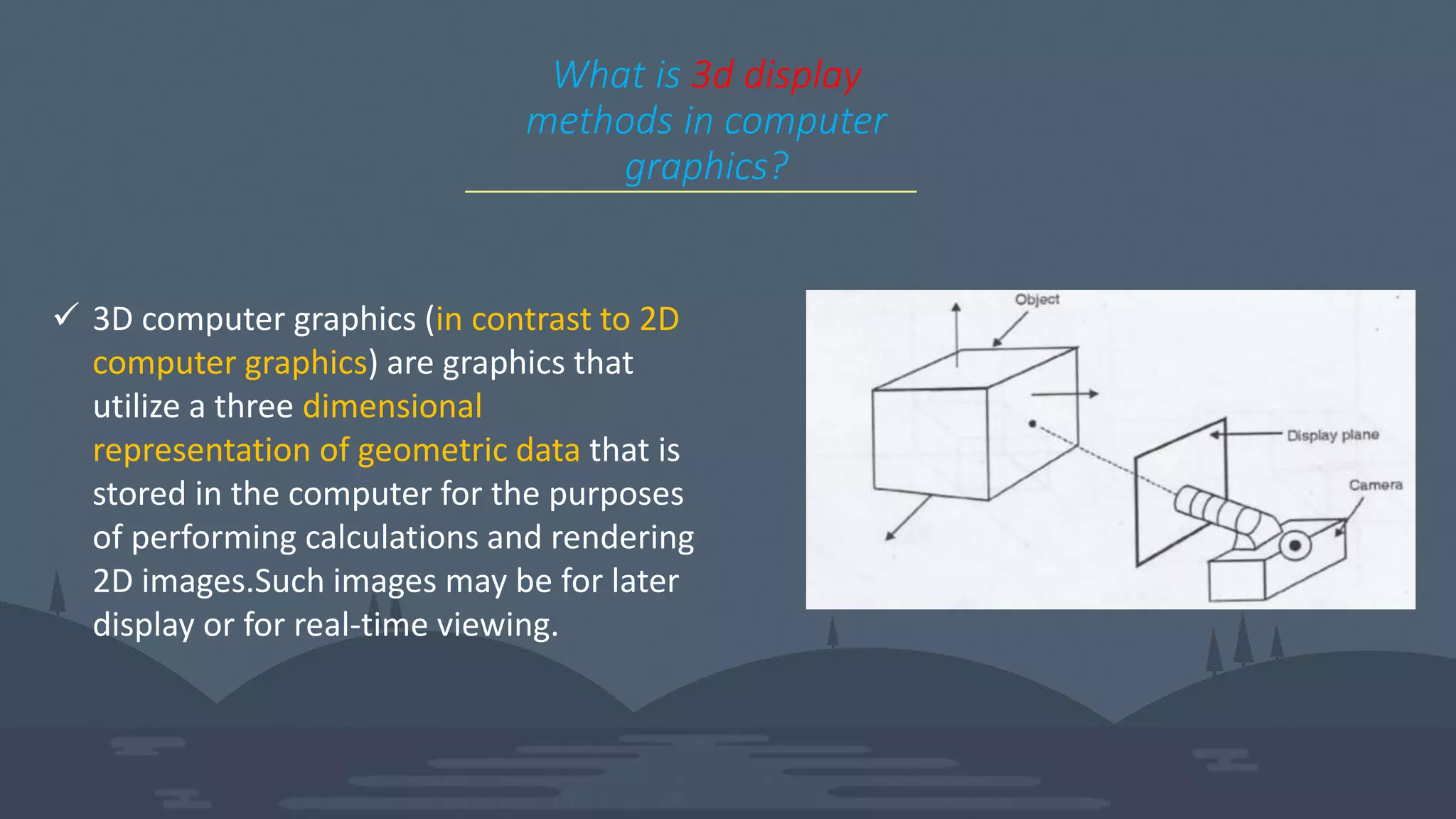
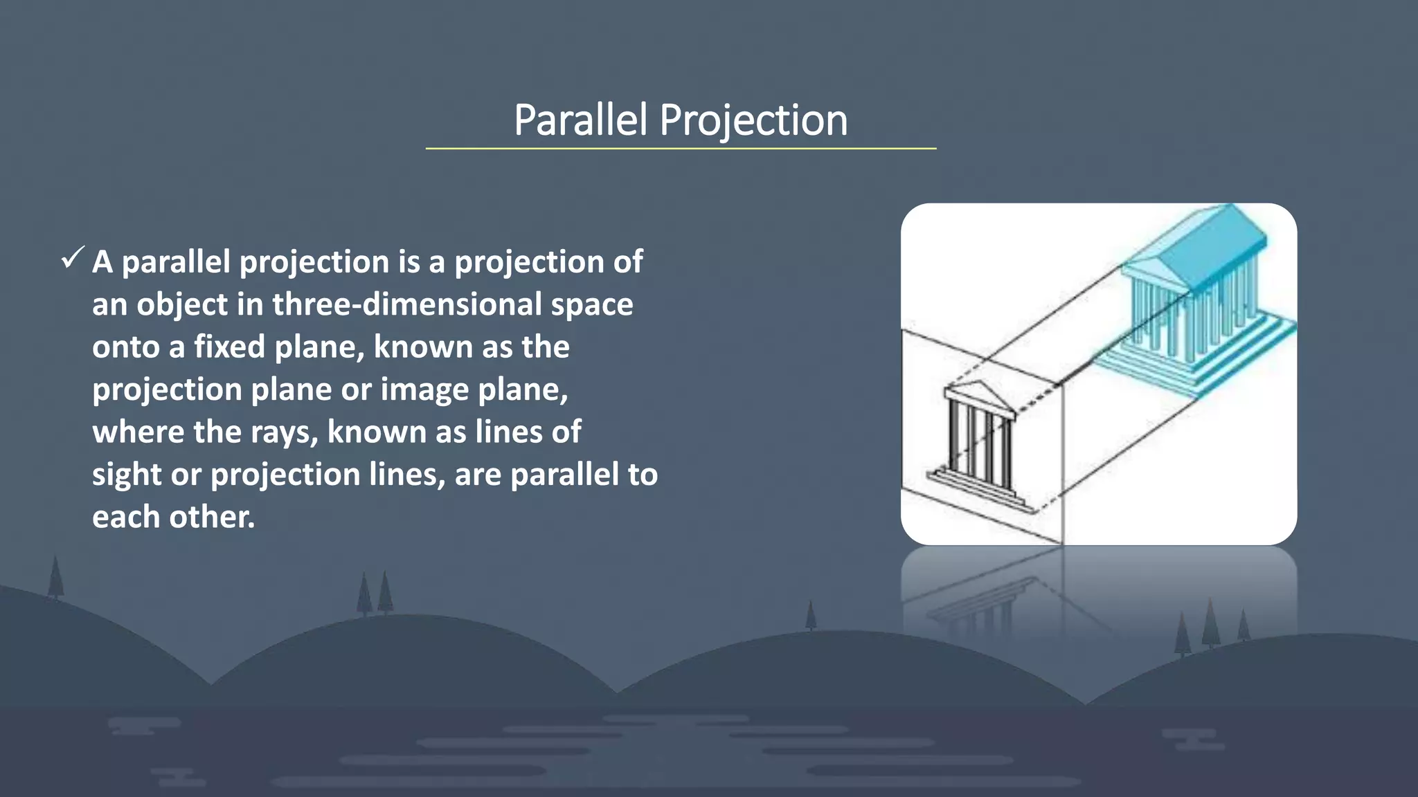
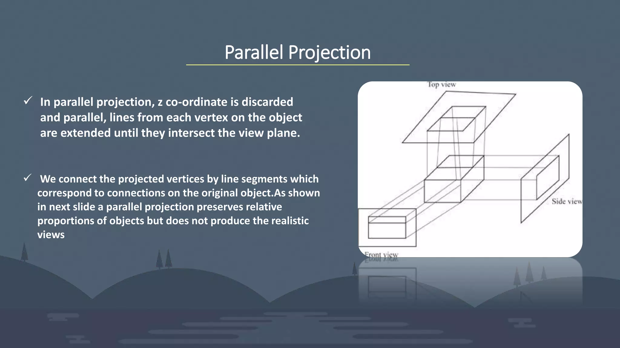
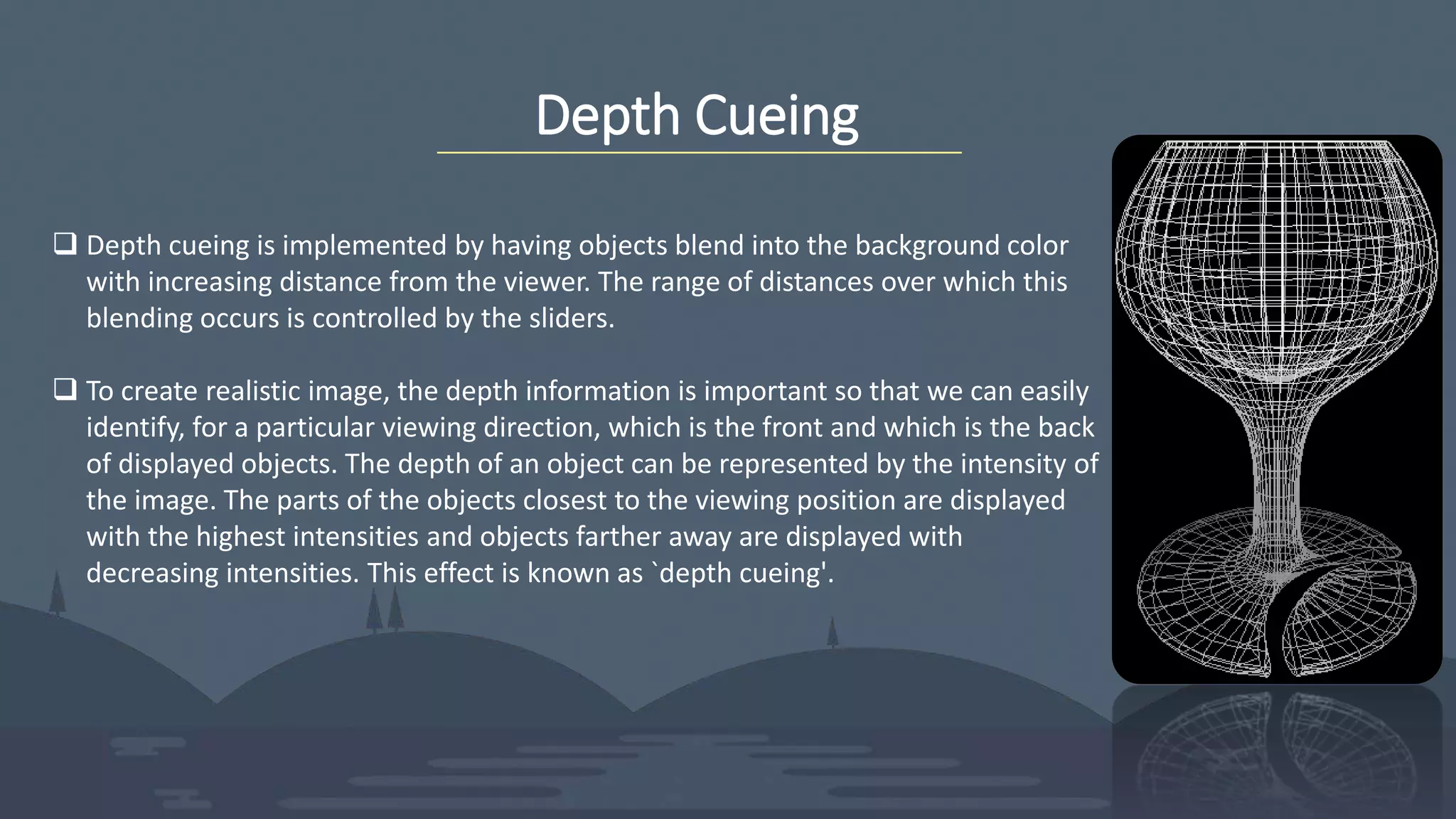
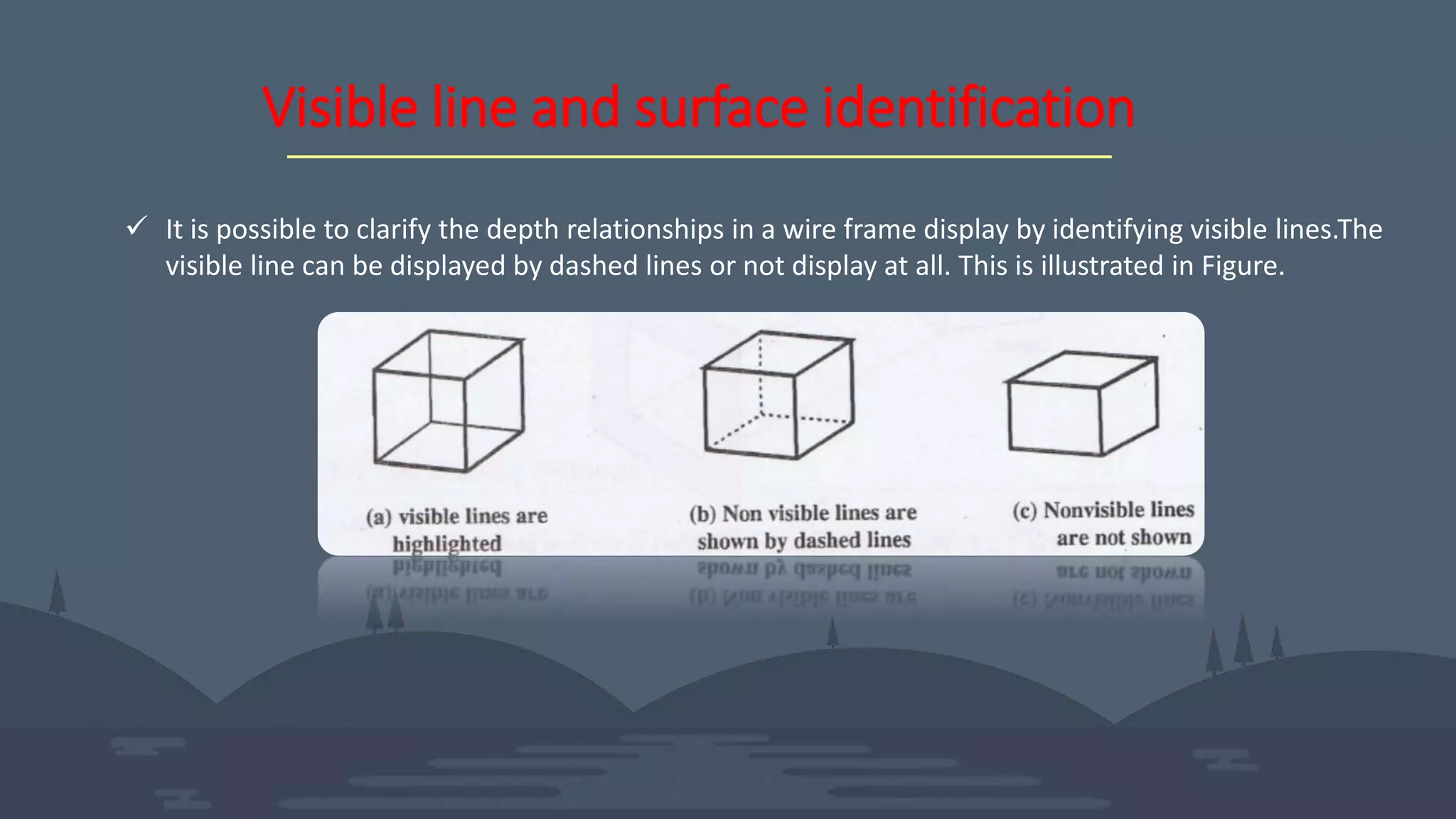
A Warm WELCOME
3D Display Methods
Group Members
Khaled Akram sany
161-15-7203
Faria Akter Eti
161-15-7337
Shami Al Rahad
161-15-7349
Md. Rayhanul Islam
161-15-7335
Selim Hossain
161-15-7351
What is 3d display
methods in computer
graphics?
 3D computer graphics (in contrast to 2D
computer graphics) are graphics that
utilize a three dimensional
representation of geometric data that is
stored in the computer for the purposes
of performing calculations and rendering
2D images.Such images may be for later
display or for real-time viewing.
Parallel Projection
 A parallel projection is a projection of
an object in three-dimensional space
onto a fixed plane, known as the
projection plane or image plane,
where the rays, known as lines of
sight or projection lines, are parallel to
each other.
Parallel Projection
 In parallel projection, z co-ordinate is discarded
and parallel, lines from each vertex on the object
are extended until they intersect the view plane.
 We connect the projected vertices by line segments which
correspond to connections on the original object.As shown
in next slide a parallel projection preserves relative
proportions of objects but does not produce the realistic
views
Parallel Projection
 Project points on the object surface along parallel
lines onto the display plane.
 Parallel lines are still parallel after projection.
 Used in engineering and architectural drawings.
 Views maintain relative proportions of the object.
Parallel Projection(Oblique Projection)
In oblique projection, the direction of projection is not normal to
the projection of plane. In oblique projection, we can view the
object better than orthographic projection.
Fig: Cavalier projection(45°) Fig: Cabinet projection (63.4°)
Perspective Projection
 The perspective projection, on the other
hand, produces realistic views but does not
preserve relative proportions. In perspective
projection, the lines of projection are not
parallel. Instead , they all converge at a
single point called the `center of projection'
or `projection reference point'.
 The perspective projection is perhaps the
most common projection technique familiar
to us as image formed by eye or lenses of
photographic flim on perspective projection.
Perspective Projection
The distance and angles are not preserved and parallel lines do not remain
parallel. Instead, they all converge at a single point called center of
projection or projection reference point. There are 3 types of perspective
projections:-
• One point perspective projection is simple to draw.
• Two point perspective projection gives better impression of depth.
• Three point perspective projection is most difficult to draw.
Perspective Projection
The perspective projection conveys depth information by
making distance object smalls than near one.
This is the way that our eyes and a camera lens form
images and so the displays are more realistic.
 The disadvantage is that if object have only limited variation ,
the image may not provide adequate depth information and
ambiquity apears.
Depth Cueing
 Depth cueing is implemented by having objects blend into the background color
with increasing distance from the viewer. The range of distances over which this
blending occurs is controlled by the sliders.
 To create realistic image, the depth information is important so that we can easily
identify, for a particular viewing direction, which is the front and which is the back
of displayed objects. The depth of an object can be represented by the intensity of
the image. The parts of the objects closest to the viewing position are displayed
with the highest intensities and objects farther away are displayed with
decreasing intensities. This effect is known as `depth cueing'.
Depth Cueing
 To easily identify the front and back of display objects.
 Depth information can be included using various
methods.
 A simple method to vary the intensity of objects
according to their distance from the viewing position.
 Eg: lines closest to the viewing position are displayed
with the higher intensities and lines farther away are
displayed with lower intensities.
Visible line and surface identification
 It is possible to clarify the depth relationships in a wire frame display by identifying visible lines.The
visible line can be displayed by dashed lines or not display at all. This is illustrated in Figure.
Visible line and surface identification
 The visible surface identification can be done with
visible surface algorithms.
 They establish visibility pixel by pixel across the viewing
plane or determine surfaces for object as a whole.
 Once the visible, surfaces are identified we can apply
surface rendering techniques on them to obscure the
hidden surfaces.
Visible line and surface identification
1.Hidden-surface problem
There are two approaches for removing hidden surface problems
1.1 Object-Space method (physical coordinate system) and
1.2 Image-space method. (physical coordinate system)
• Depth Buffer (Z-Buffer) Method
• Scan-Line Method
• Area-Subdivision Method
• Back-Face Detection
• A-Buffer Method
• Depth Sorting Method
• Binary Space Partition (BSP) Trees
When we want to display a 3D object on a 2D screen, we need to identify those
parts of a screen that are visible from a chosen viewing position.
Visible line and surface identification
Highlight the visible lines or display
them in different color
Display nonvisible lines as dashed lines
Remove the nonvisible lines
Surface Rendering
 Surface rendering involves setting the surface intensity of objects
according to the lighting conditions in the scene and according to
assigned surface characteristics. The lighting conditions specify the
intensity and positions of light sources and the general background
illumination required for a scene .
 On the other hand the surface characteristics of objects specify the
degree of transparency and smoothness or roughness of the
surface; usually the surface rendering methods are combined with
perspective and visible surface identification to generate a high
degree of realism in a displayed scene.
Surface Rendering
Set the surface intensity of objects according to
 Lighting conditions in the scene
 Assigned surface characteristics
 Lighting specifications include the intensity and positions
of light sources and the general background illumination
required for a scene.
Surface properties include degree of transparency and
how rough or smooth of the surfaces
3 d display methods

3 d display methods

  • 1.
  • 2.
  • 3.
    Group Members Khaled Akramsany 161-15-7203 Faria Akter Eti 161-15-7337 Shami Al Rahad 161-15-7349 Md. Rayhanul Islam 161-15-7335 Selim Hossain 161-15-7351
  • 4.
    What is 3ddisplay methods in computer graphics?  3D computer graphics (in contrast to 2D computer graphics) are graphics that utilize a three dimensional representation of geometric data that is stored in the computer for the purposes of performing calculations and rendering 2D images.Such images may be for later display or for real-time viewing.
  • 5.
    Parallel Projection  Aparallel projection is a projection of an object in three-dimensional space onto a fixed plane, known as the projection plane or image plane, where the rays, known as lines of sight or projection lines, are parallel to each other.
  • 6.
    Parallel Projection  Inparallel projection, z co-ordinate is discarded and parallel, lines from each vertex on the object are extended until they intersect the view plane.  We connect the projected vertices by line segments which correspond to connections on the original object.As shown in next slide a parallel projection preserves relative proportions of objects but does not produce the realistic views
  • 7.
    Parallel Projection  Projectpoints on the object surface along parallel lines onto the display plane.  Parallel lines are still parallel after projection.  Used in engineering and architectural drawings.  Views maintain relative proportions of the object.
  • 8.
    Parallel Projection(Oblique Projection) Inoblique projection, the direction of projection is not normal to the projection of plane. In oblique projection, we can view the object better than orthographic projection. Fig: Cavalier projection(45°) Fig: Cabinet projection (63.4°)
  • 9.
    Perspective Projection  Theperspective projection, on the other hand, produces realistic views but does not preserve relative proportions. In perspective projection, the lines of projection are not parallel. Instead , they all converge at a single point called the `center of projection' or `projection reference point'.  The perspective projection is perhaps the most common projection technique familiar to us as image formed by eye or lenses of photographic flim on perspective projection.
  • 10.
    Perspective Projection The distanceand angles are not preserved and parallel lines do not remain parallel. Instead, they all converge at a single point called center of projection or projection reference point. There are 3 types of perspective projections:- • One point perspective projection is simple to draw. • Two point perspective projection gives better impression of depth. • Three point perspective projection is most difficult to draw.
  • 11.
    Perspective Projection The perspectiveprojection conveys depth information by making distance object smalls than near one. This is the way that our eyes and a camera lens form images and so the displays are more realistic.  The disadvantage is that if object have only limited variation , the image may not provide adequate depth information and ambiquity apears.
  • 12.
    Depth Cueing  Depthcueing is implemented by having objects blend into the background color with increasing distance from the viewer. The range of distances over which this blending occurs is controlled by the sliders.  To create realistic image, the depth information is important so that we can easily identify, for a particular viewing direction, which is the front and which is the back of displayed objects. The depth of an object can be represented by the intensity of the image. The parts of the objects closest to the viewing position are displayed with the highest intensities and objects farther away are displayed with decreasing intensities. This effect is known as `depth cueing'.
  • 13.
    Depth Cueing  Toeasily identify the front and back of display objects.  Depth information can be included using various methods.  A simple method to vary the intensity of objects according to their distance from the viewing position.  Eg: lines closest to the viewing position are displayed with the higher intensities and lines farther away are displayed with lower intensities.
  • 14.
    Visible line andsurface identification  It is possible to clarify the depth relationships in a wire frame display by identifying visible lines.The visible line can be displayed by dashed lines or not display at all. This is illustrated in Figure.
  • 15.
    Visible line andsurface identification  The visible surface identification can be done with visible surface algorithms.  They establish visibility pixel by pixel across the viewing plane or determine surfaces for object as a whole.  Once the visible, surfaces are identified we can apply surface rendering techniques on them to obscure the hidden surfaces.
  • 16.
    Visible line andsurface identification 1.Hidden-surface problem There are two approaches for removing hidden surface problems 1.1 Object-Space method (physical coordinate system) and 1.2 Image-space method. (physical coordinate system) • Depth Buffer (Z-Buffer) Method • Scan-Line Method • Area-Subdivision Method • Back-Face Detection • A-Buffer Method • Depth Sorting Method • Binary Space Partition (BSP) Trees When we want to display a 3D object on a 2D screen, we need to identify those parts of a screen that are visible from a chosen viewing position.
  • 17.
    Visible line andsurface identification Highlight the visible lines or display them in different color Display nonvisible lines as dashed lines Remove the nonvisible lines
  • 18.
    Surface Rendering  Surfacerendering involves setting the surface intensity of objects according to the lighting conditions in the scene and according to assigned surface characteristics. The lighting conditions specify the intensity and positions of light sources and the general background illumination required for a scene .  On the other hand the surface characteristics of objects specify the degree of transparency and smoothness or roughness of the surface; usually the surface rendering methods are combined with perspective and visible surface identification to generate a high degree of realism in a displayed scene.
  • 19.
    Surface Rendering Set thesurface intensity of objects according to  Lighting conditions in the scene  Assigned surface characteristics  Lighting specifications include the intensity and positions of light sources and the general background illumination required for a scene. Surface properties include degree of transparency and how rough or smooth of the surfaces