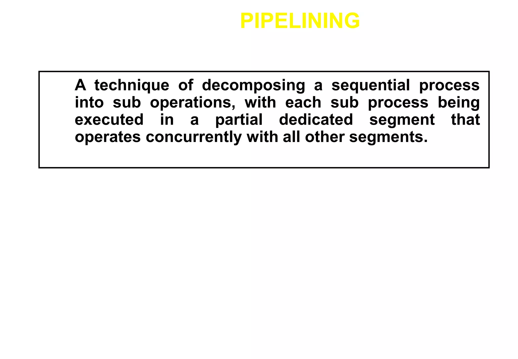
This document discusses pipelining techniques used to improve the performance of arithmetic and instruction processing. It describes how pipelining decomposes operations into sequential sub-operations that can execute concurrently across multiple pipeline stages. In arithmetic pipelining, it provides examples of a floating point adder broken into four stages: compare exponents, align mantissa, add/subtract mantissa, and normalize result. For instruction pipelining, it outlines a four-stage RISC pipeline of fetch, decode/address, fetch operands, and execute stages and how dependencies are handled through techniques like delayed loading and branching.

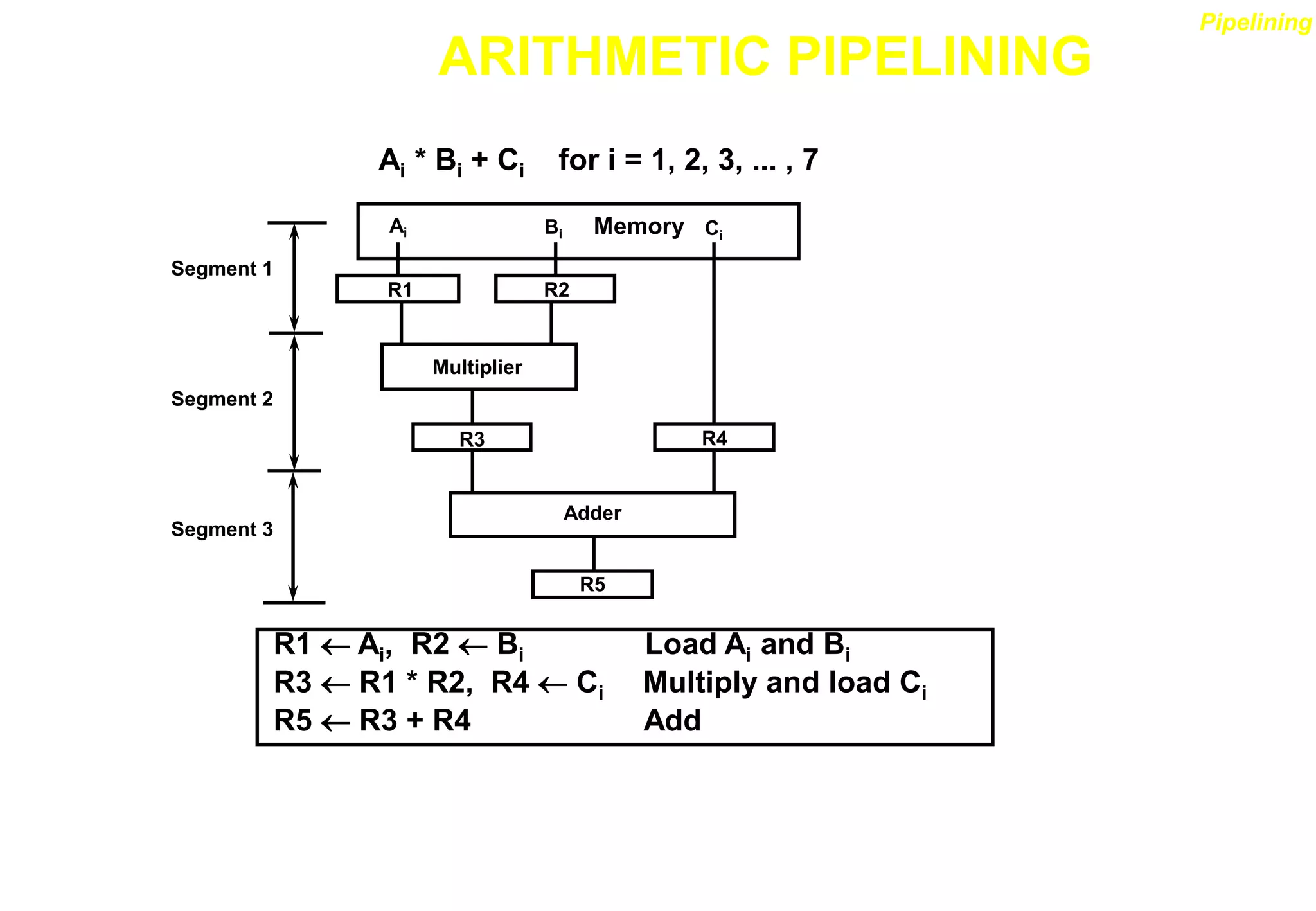
![ARITHMETIC PIPELINE
Floating-point adder
[1] Compare the exponents
[2] Align the mantissa
[3] Add/sub the mantissa
[4] Normalize the result
X = A x 2a
Y = B x 2b
R
Compare
exponents
by subtraction
a b
R
Choose exponent
Exponents
R
A B
Align mantissa
Mantissas
Difference
R
Add or subtract
mantissas
R
Normalize
result
R
R
Adjust
exponent
R
Segment 1:
Segment 2:
Segment 3:
Segment 4:](https://image.slidesharecdn.com/pipeline-r014-211207140820/75/Pipeline-r014-10-2048.jpg)

![INSTRUCTION CYCLE
Six Phases* in an Instruction Cycle
[1] Fetch an instruction from memory
[2] Decode the instruction
[3] Calculate the effective address of the operand
[4] Fetch the operands from memory
[5] Execute the operation
[6] Store the result in the proper place
* Some instructions skip some phases
* Effective address calculation can be done in
the part of the decoding phase
* Storage of the operation result into a register
is done automatically in the execution phase
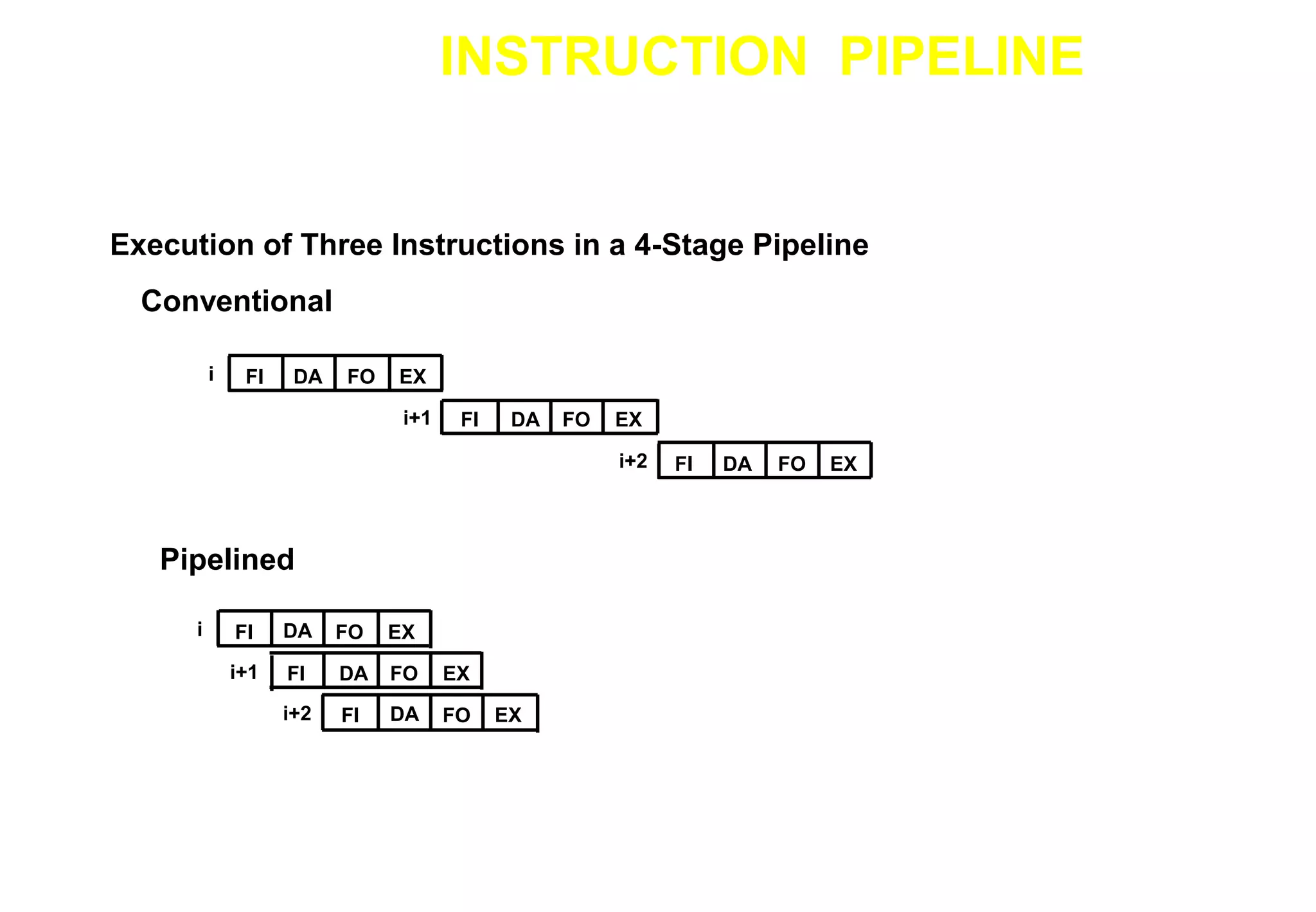
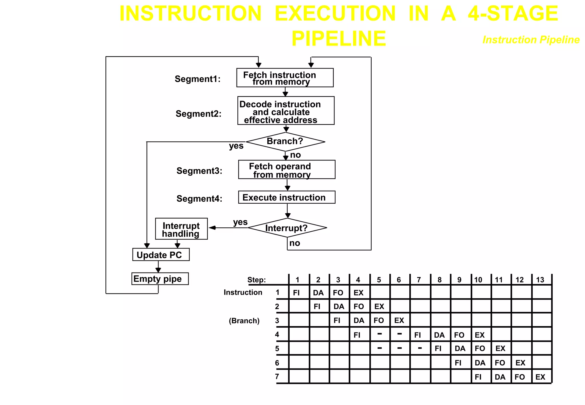
==> 4-Stage Pipeline
[1] FI: Fetch an instruction from memory
[2] DA: Decode the instruction and calculate
the effective address of the operand
[3] FO: Fetch the operand
[4] EX: Execute the operation
Instruction Pipeline](https://image.slidesharecdn.com/pipeline-r014-211207140820/75/Pipeline-r014-13-2048.jpg)
![DELAYED LOAD
Three-segment pipeline timing
Pipeline timing with data conflict
clock cycle 1 2 3 4 5 6
Load R1 I A E
Load R2 I A E
Add R1+R2 I A E
Store R3 I A E
Pipeline timing with delayed load
clock cycle 1 2 3 4 5 6 7
Load R1 I A E
Load R2 I A E
NOP I A E
Add R1+R2 I A E
Store R3 I A E
LOAD: R1 M[address 1]
LOAD: R2 M[address 2]
ADD: R3 R1 + R2
STORE: M[address 3] R3
RISC Pipeline
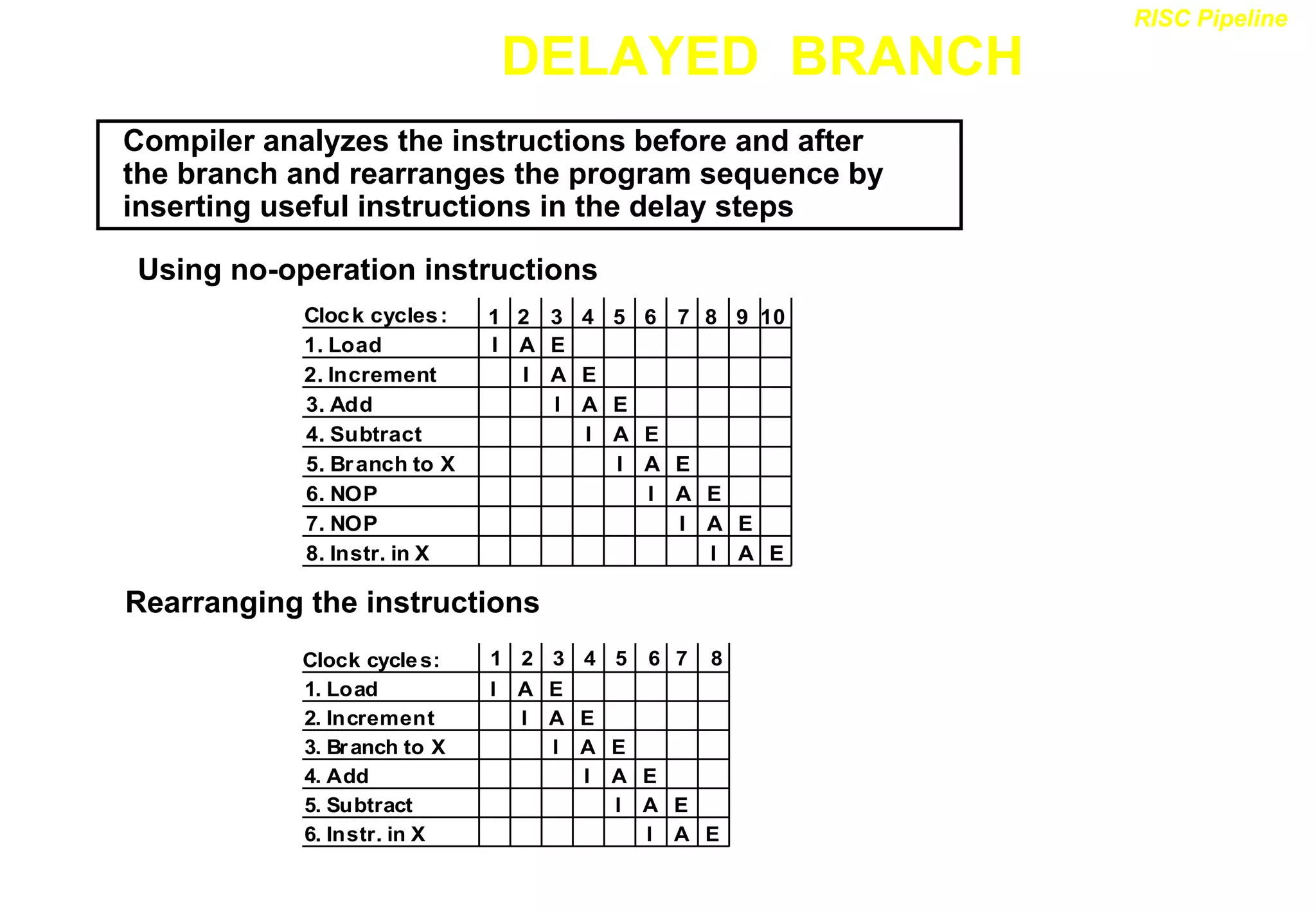
The data dependency is taken
care by the compiler rather
than the hardware
M[address 1] = 2000
M[address 2] =2001
Value at 2000 = 5
Value at 2001 =8
R1=5
R2=8
R3=5+8=13
M[address 3] =2003
2003<-r3
2003=13](https://image.slidesharecdn.com/pipeline-r014-211207140820/75/Pipeline-r014-17-2048.jpg)


![ARITHMETIC PIPELINE
Floating-point adder
[1] Compare the exponents
[2] Align the mantissa
[3] Add/sub the mantissa
[4] Normalize the result
X = A x 2a
Y = B x 2b
R
Compare
exponents
by subtraction
a b
R
Choose exponent
Exponents
R
A B
Align mantissa
Mantissas
Difference
R
Add or subtract
mantissas
R
Normalize
result
R
R
Adjust
exponent
R
Segment 1:
Segment 2:
Segment 3:
Segment 4:](https://crownmelresort.com/image.slidesharecdn.com/pipeline-r014-211207140820/75/Pipeline-r014-10-2048.jpg)


![INSTRUCTION CYCLE
Six Phases* in an Instruction Cycle
[1] Fetch an instruction from memory
[2] Decode the instruction
[3] Calculate the effective address of the operand
[4] Fetch the operands from memory
[5] Execute the operation
[6] Store the result in the proper place
* Some instructions skip some phases
* Effective address calculation can be done in
the part of the decoding phase
* Storage of the operation result into a register
is done automatically in the execution phase
==> 4-Stage Pipeline
[1] FI: Fetch an instruction from memory
[2] DA: Decode the instruction and calculate
the effective address of the operand
[3] FO: Fetch the operand
[4] EX: Execute the operation
Instruction Pipeline](https://crownmelresort.com/image.slidesharecdn.com/pipeline-r014-211207140820/75/Pipeline-r014-13-2048.jpg)


![DELAYED LOAD
Three-segment pipeline timing
Pipeline timing with data conflict
clock cycle 1 2 3 4 5 6
Load R1 I A E
Load R2 I A E
Add R1+R2 I A E
Store R3 I A E
Pipeline timing with delayed load
clock cycle 1 2 3 4 5 6 7
Load R1 I A E
Load R2 I A E
NOP I A E
Add R1+R2 I A E
Store R3 I A E
LOAD: R1 M[address 1]
LOAD: R2 M[address 2]
ADD: R3 R1 + R2
STORE: M[address 3] R3
RISC Pipeline
The data dependency is taken
care by the compiler rather
than the hardware
M[address 1] = 2000
M[address 2] =2001
Value at 2000 = 5
Value at 2001 =8
R1=5
R2=8
R3=5+8=13
M[address 3] =2003
2003<-r3
2003=13](https://crownmelresort.com/image.slidesharecdn.com/pipeline-r014-211207140820/75/Pipeline-r014-17-2048.jpg)