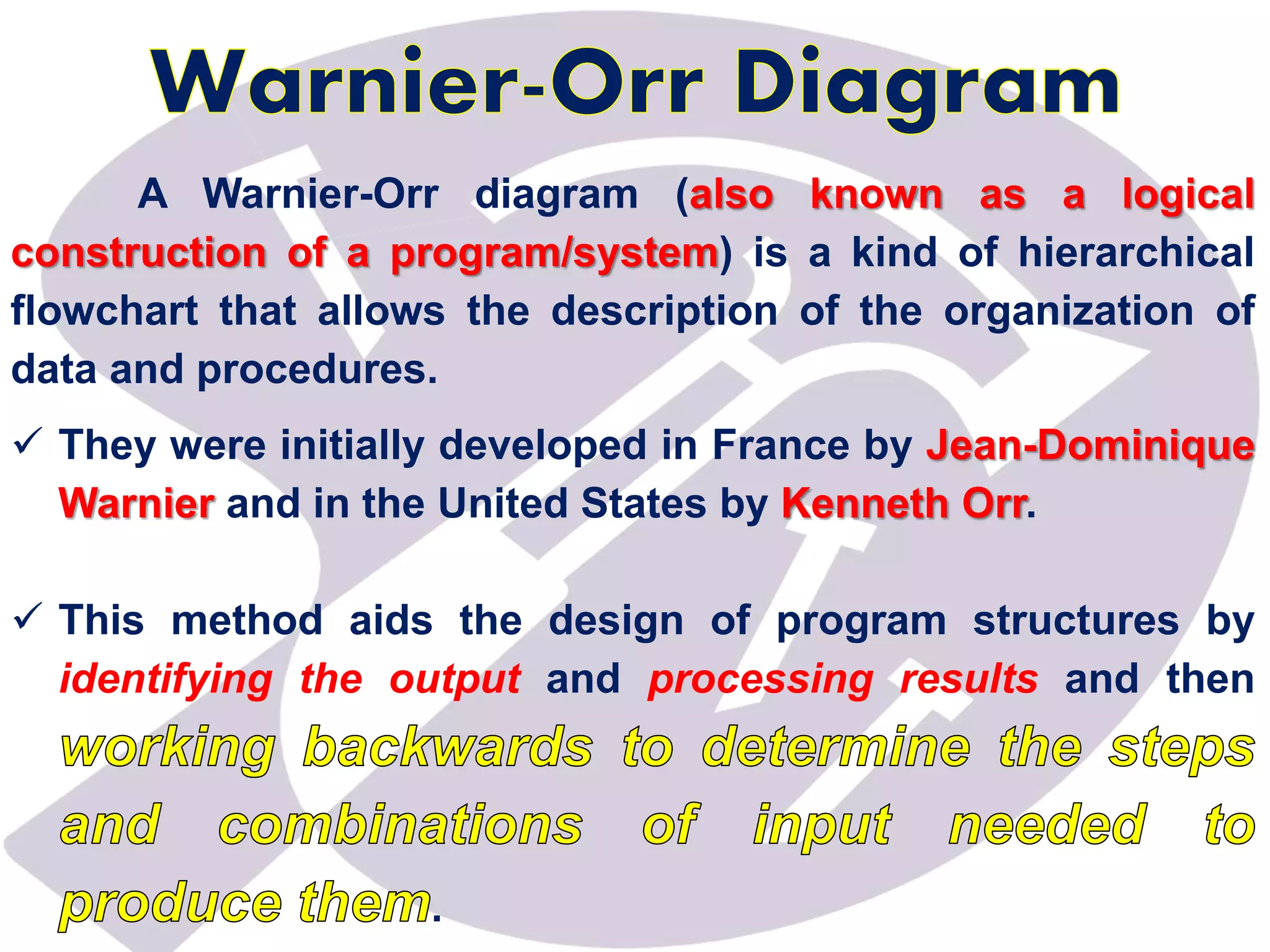
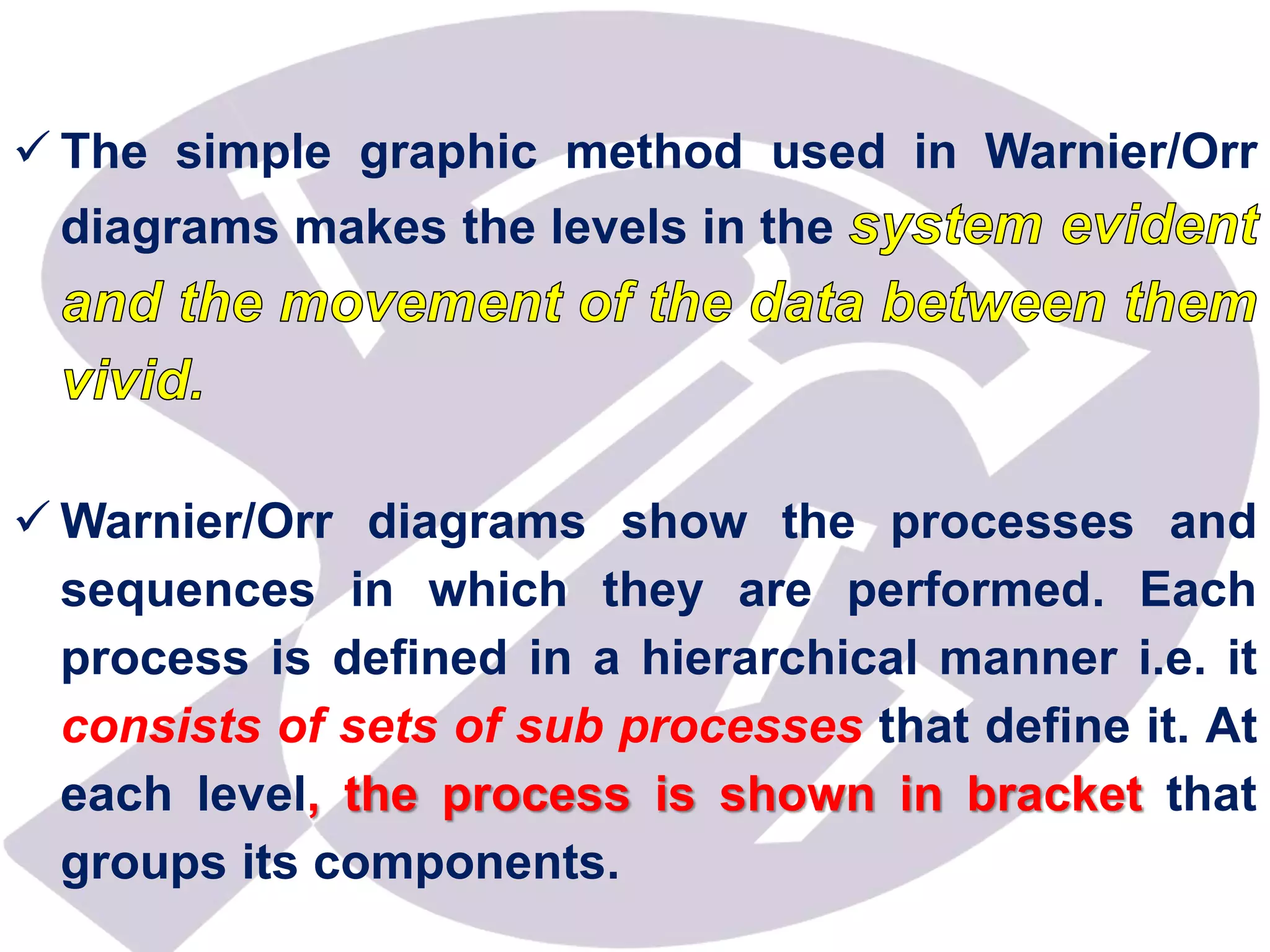
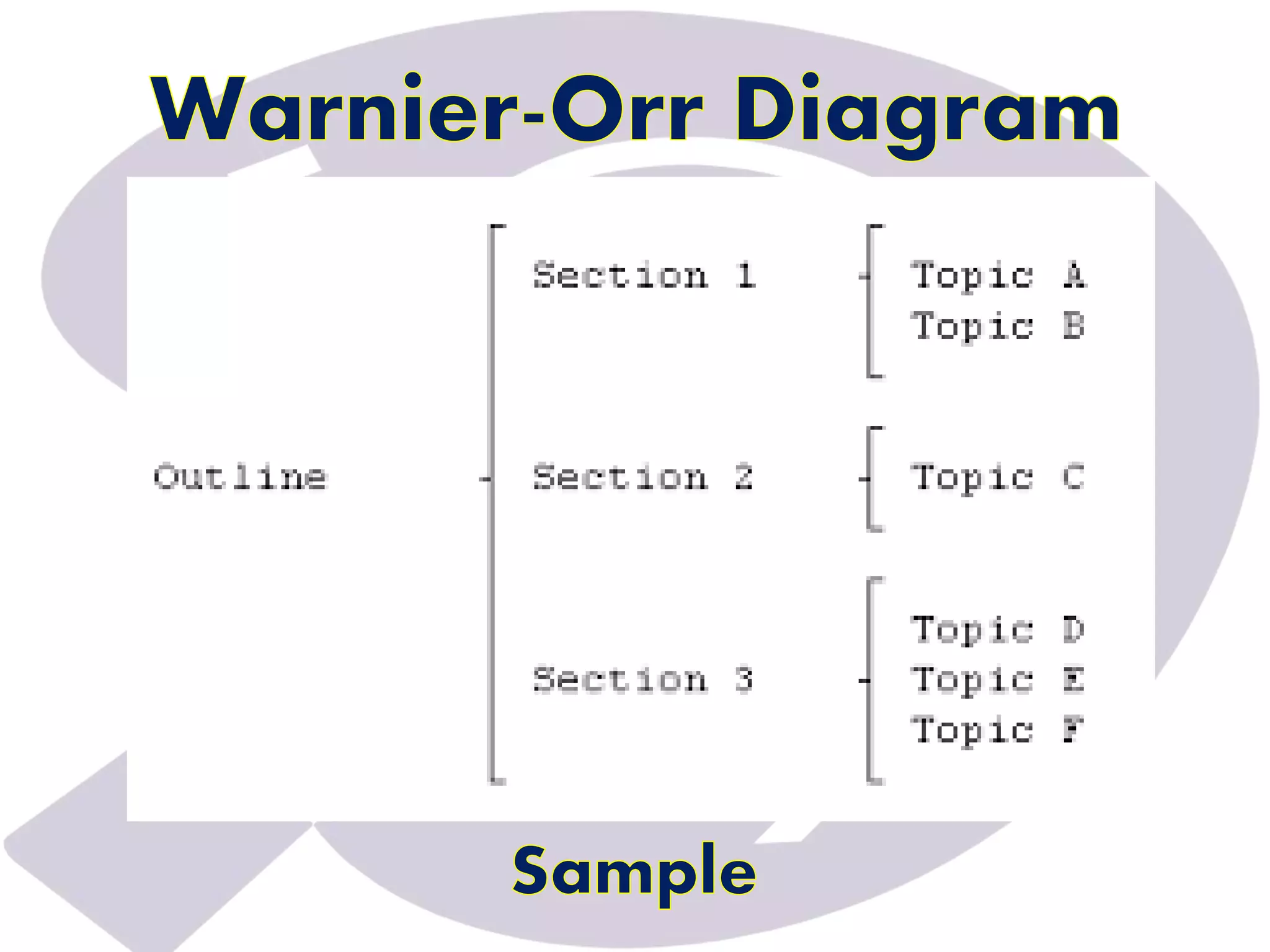
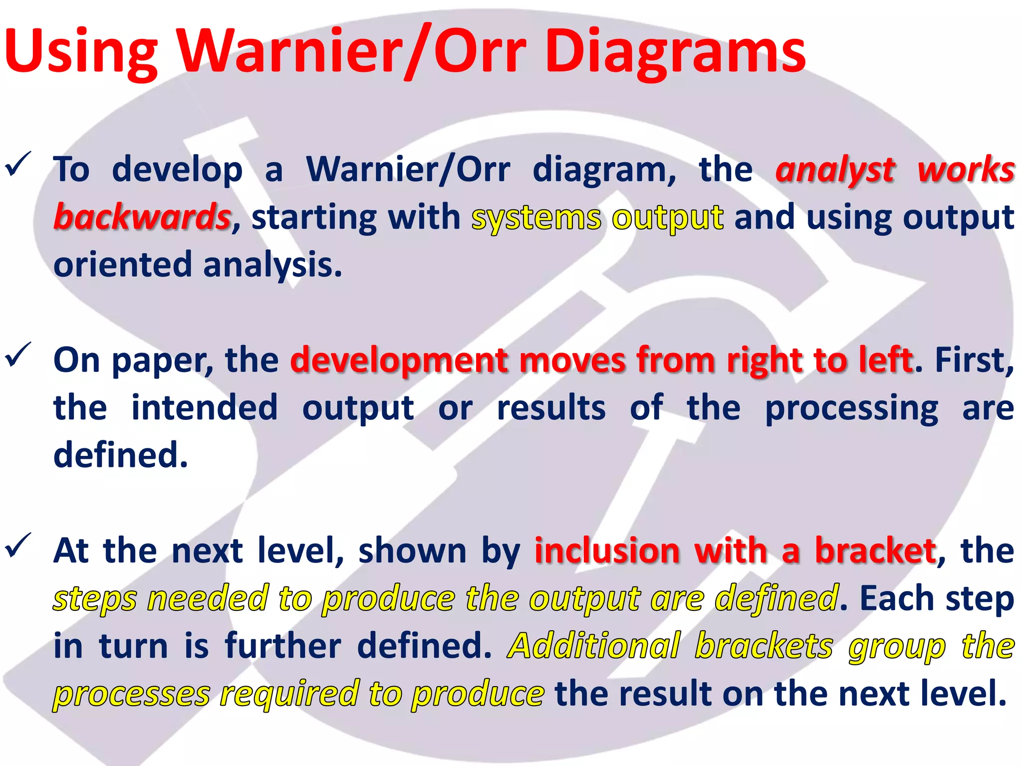
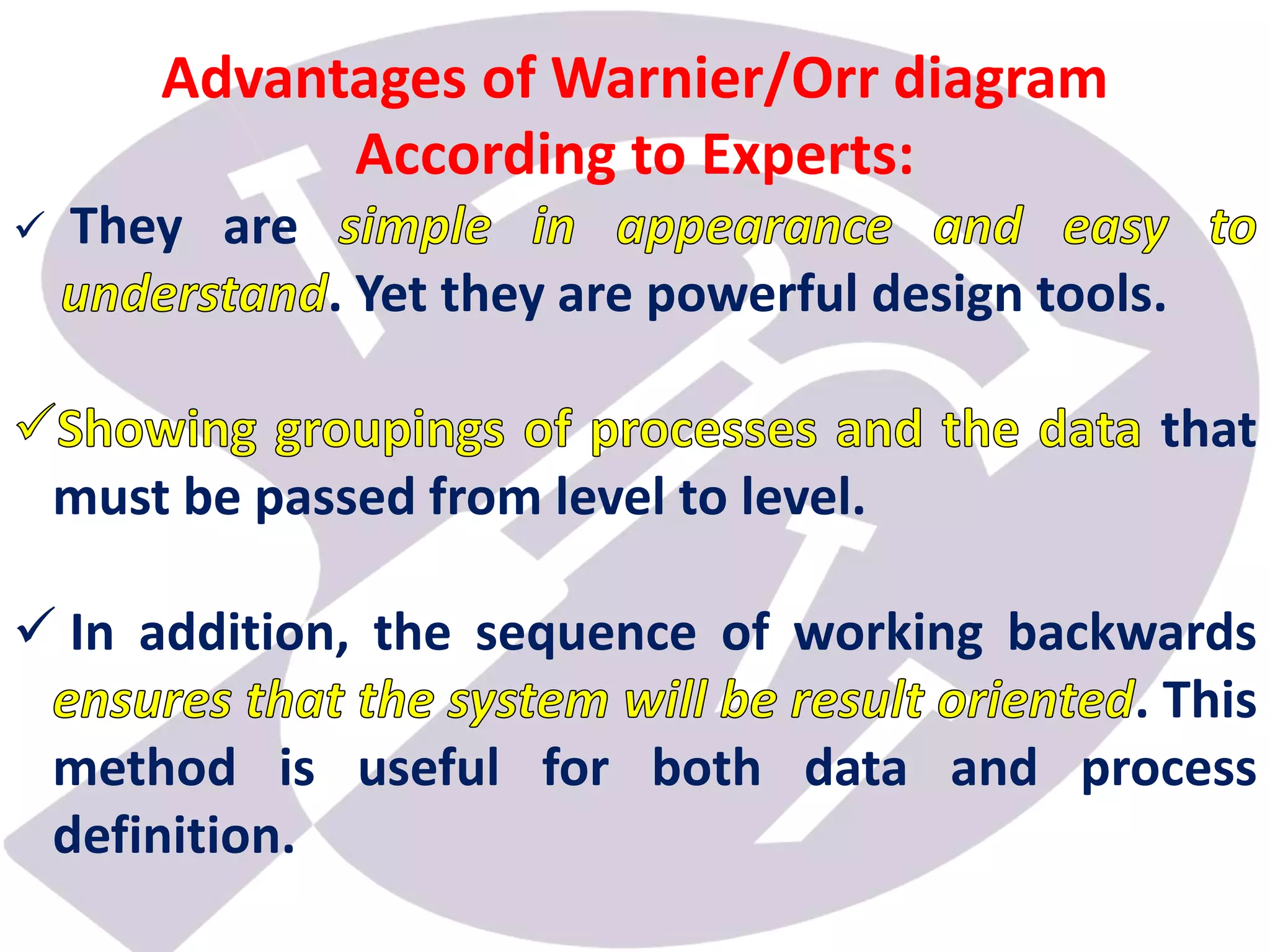
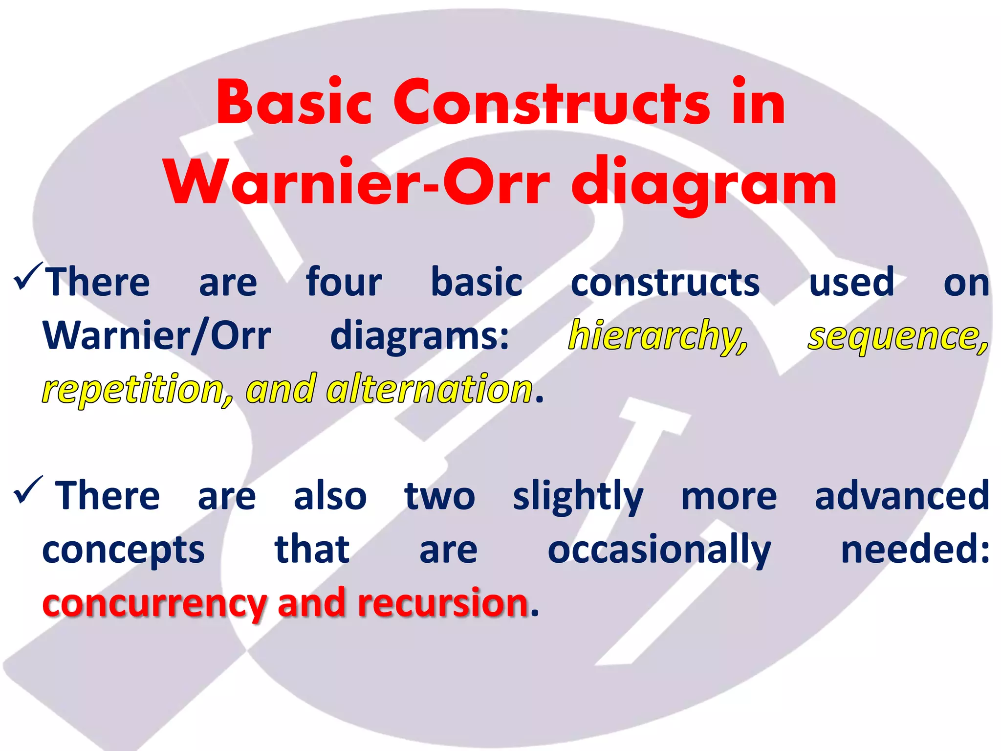
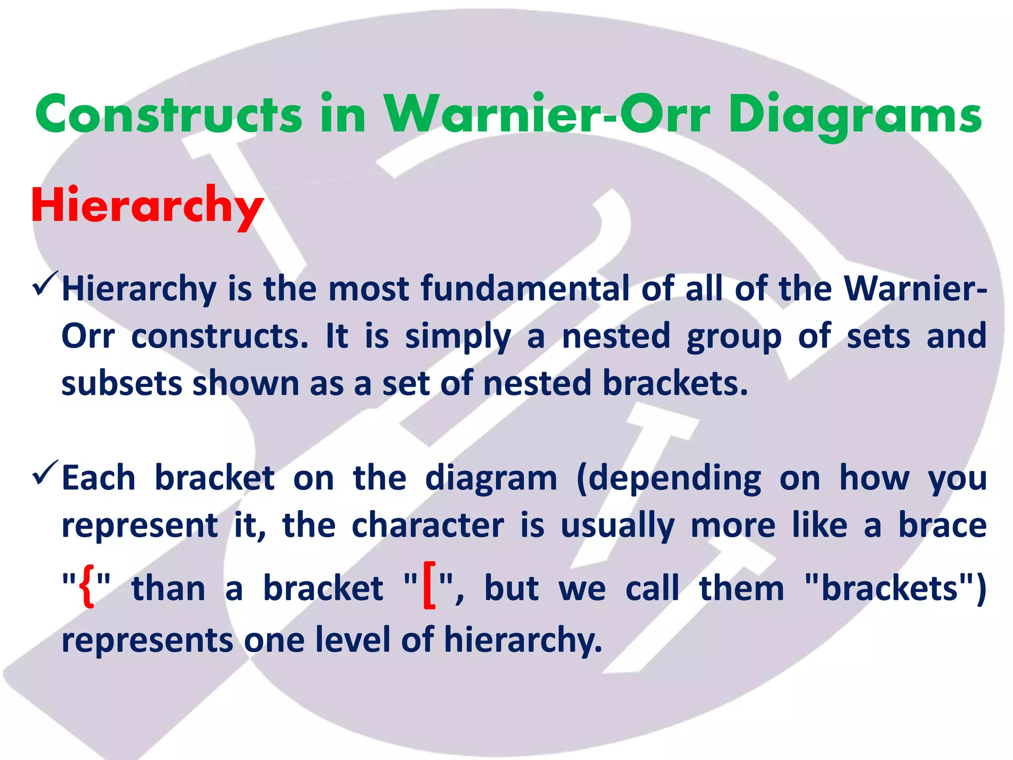
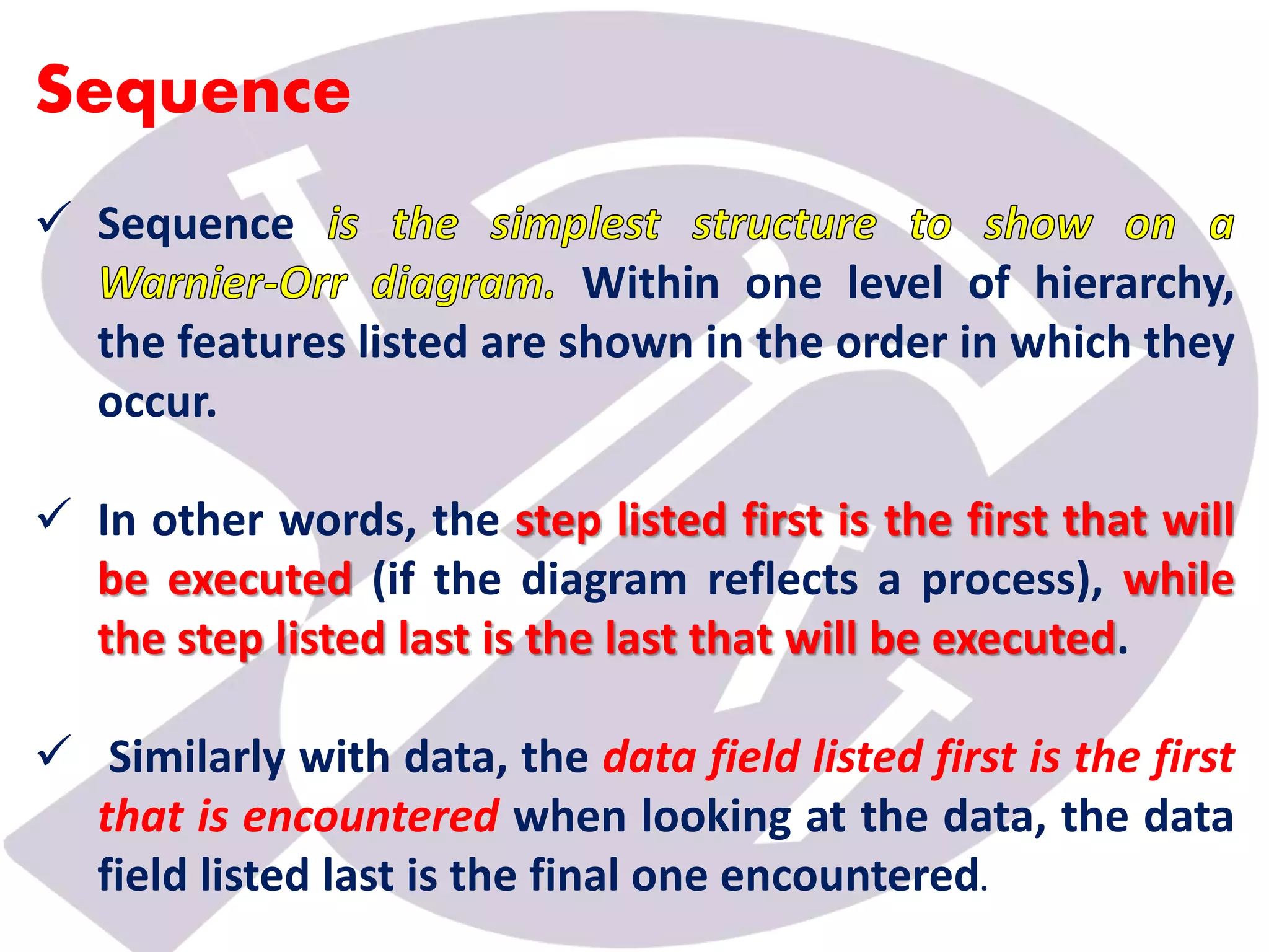
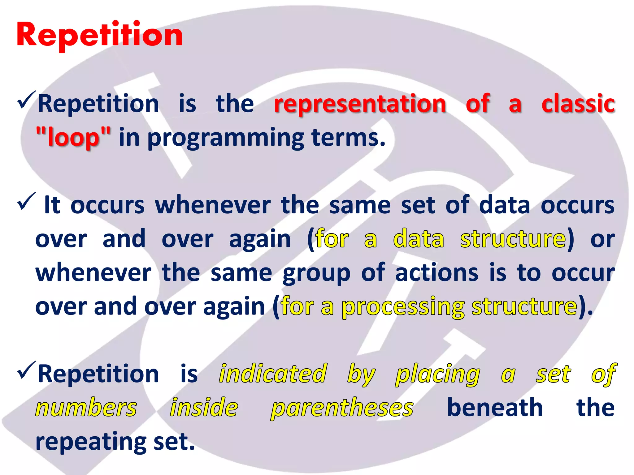
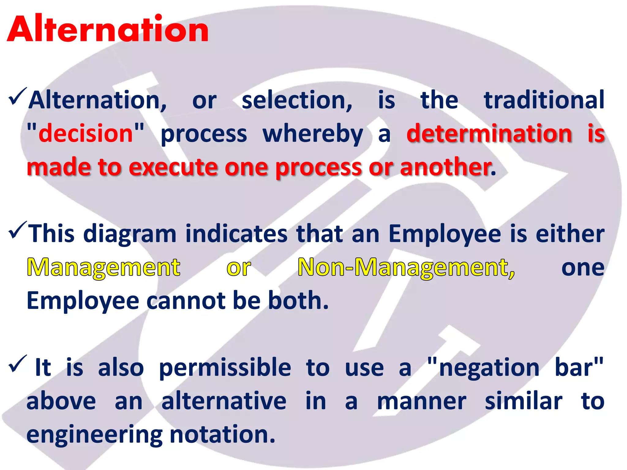
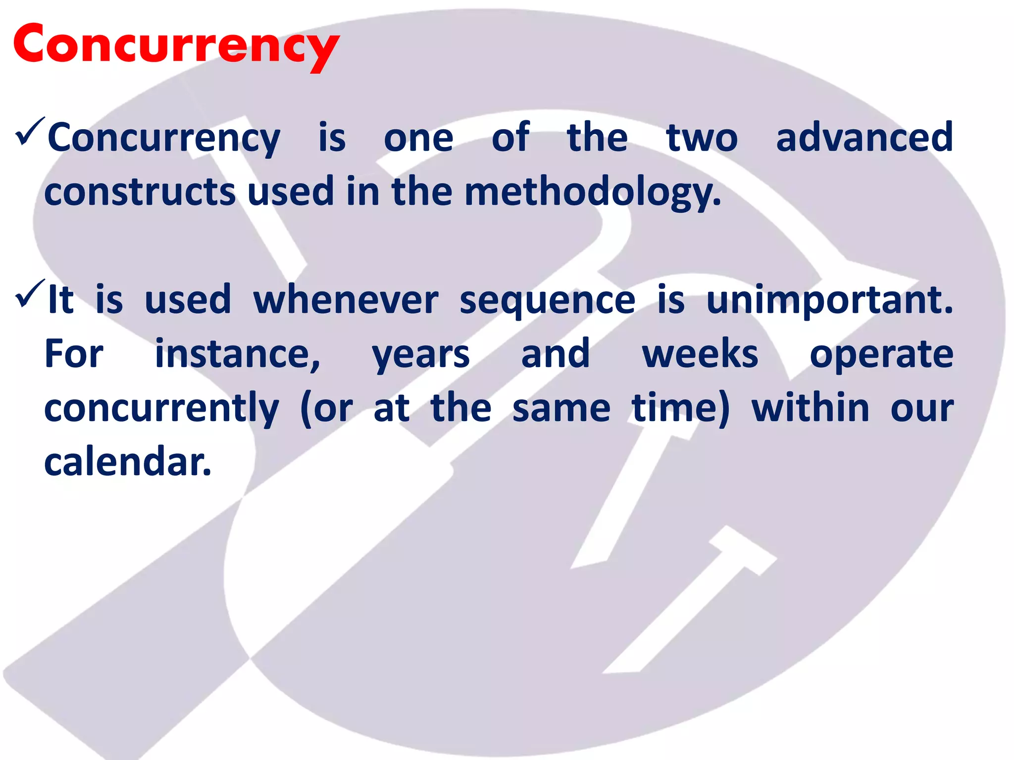
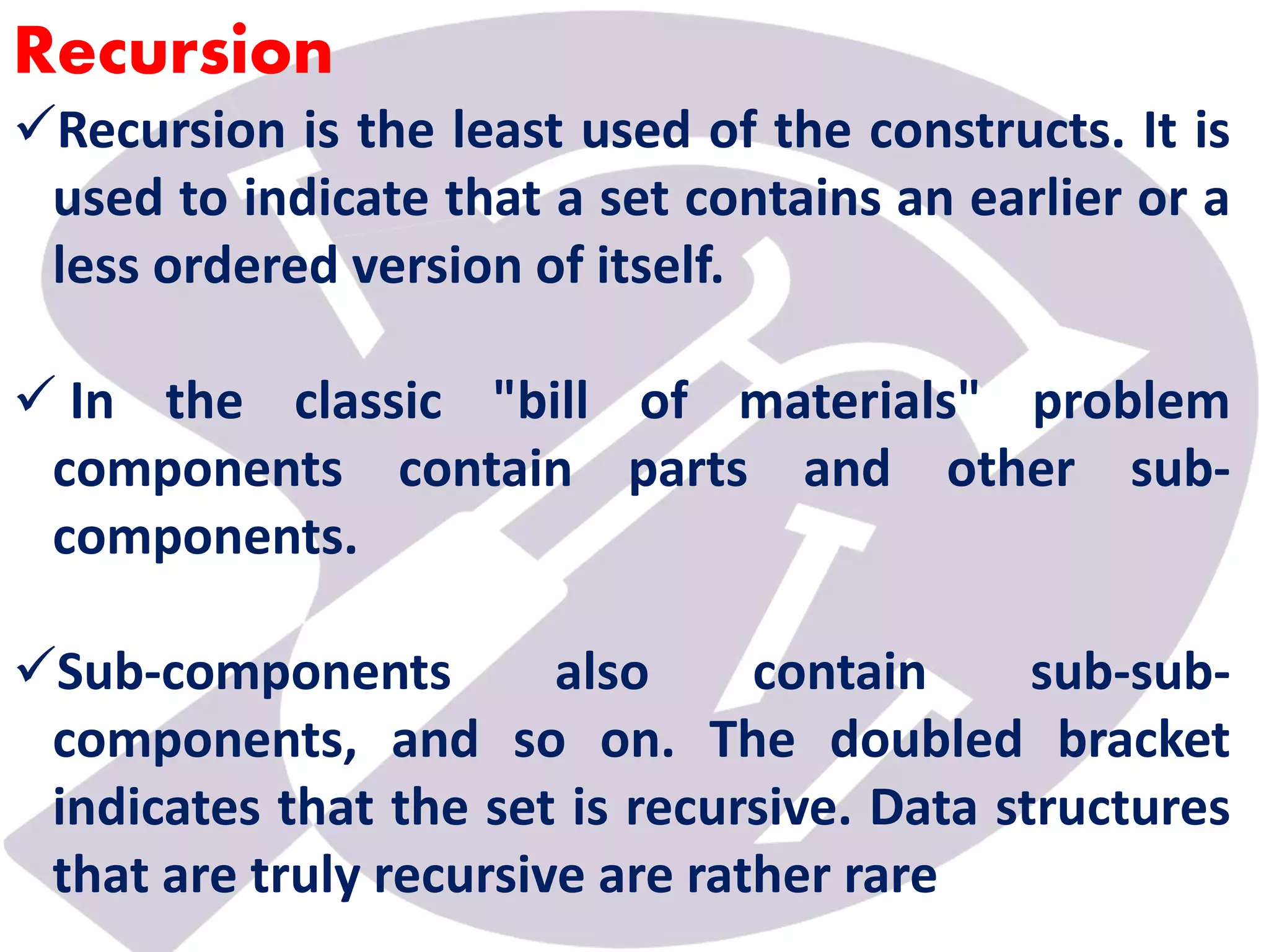
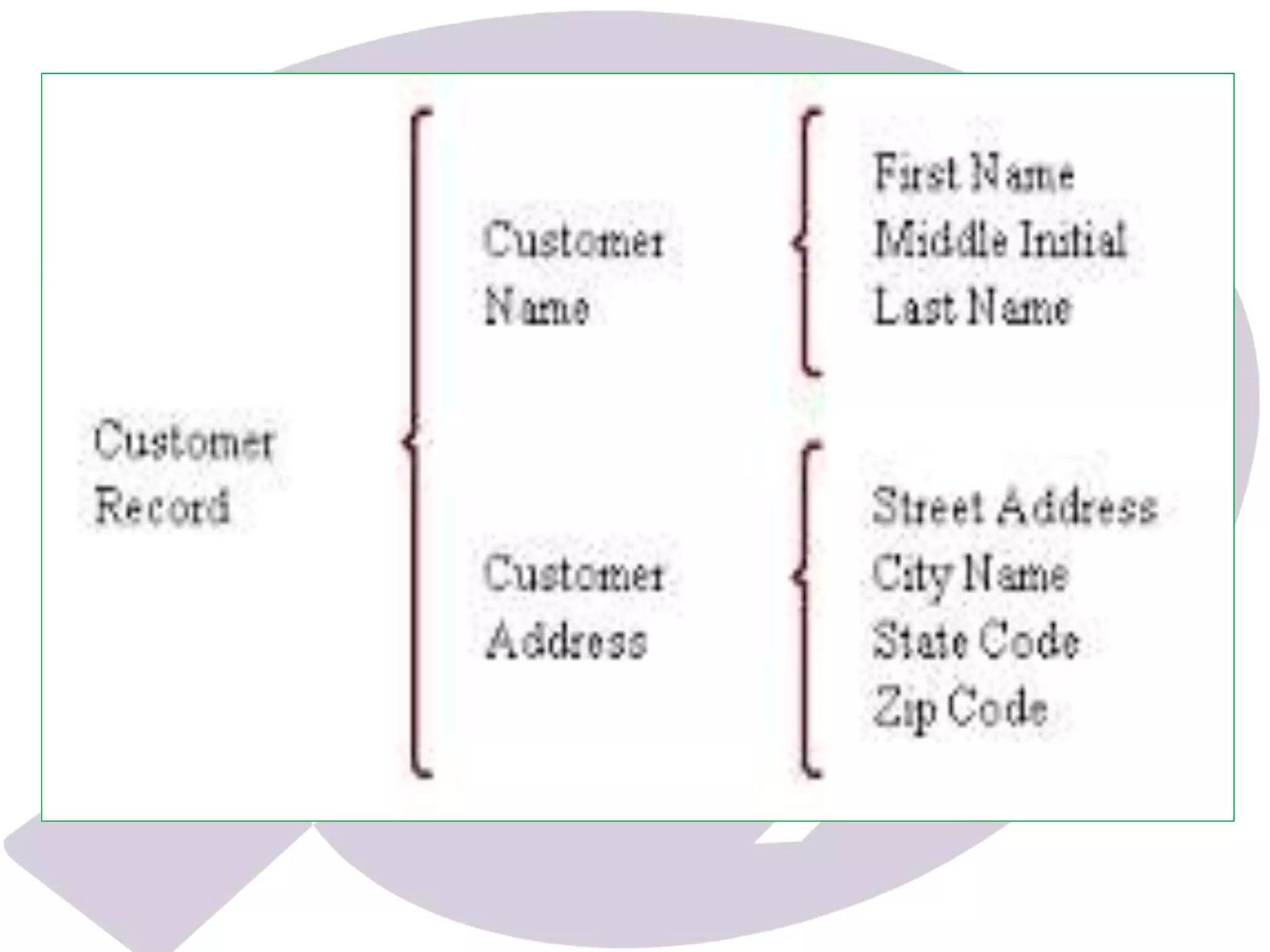
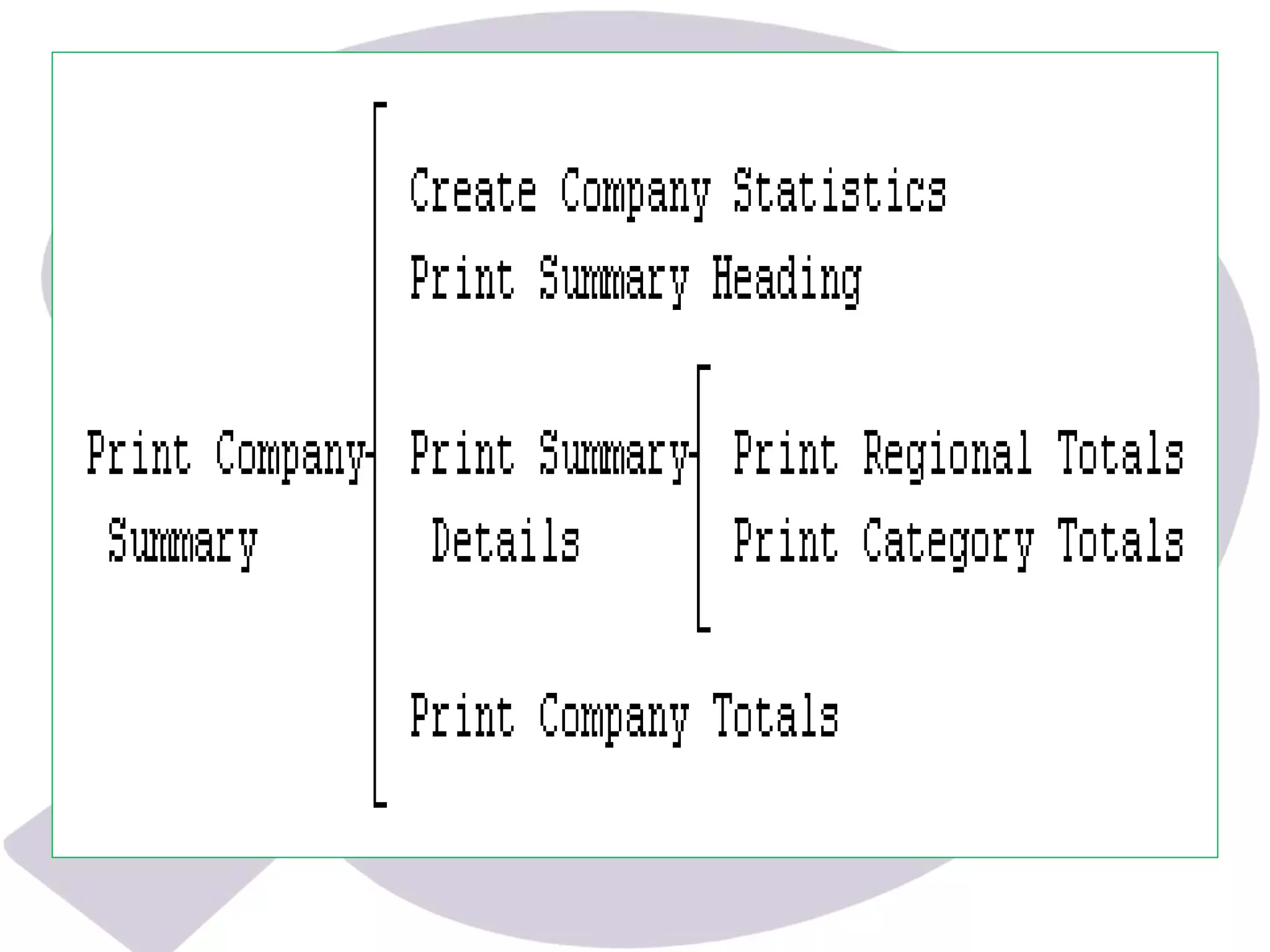
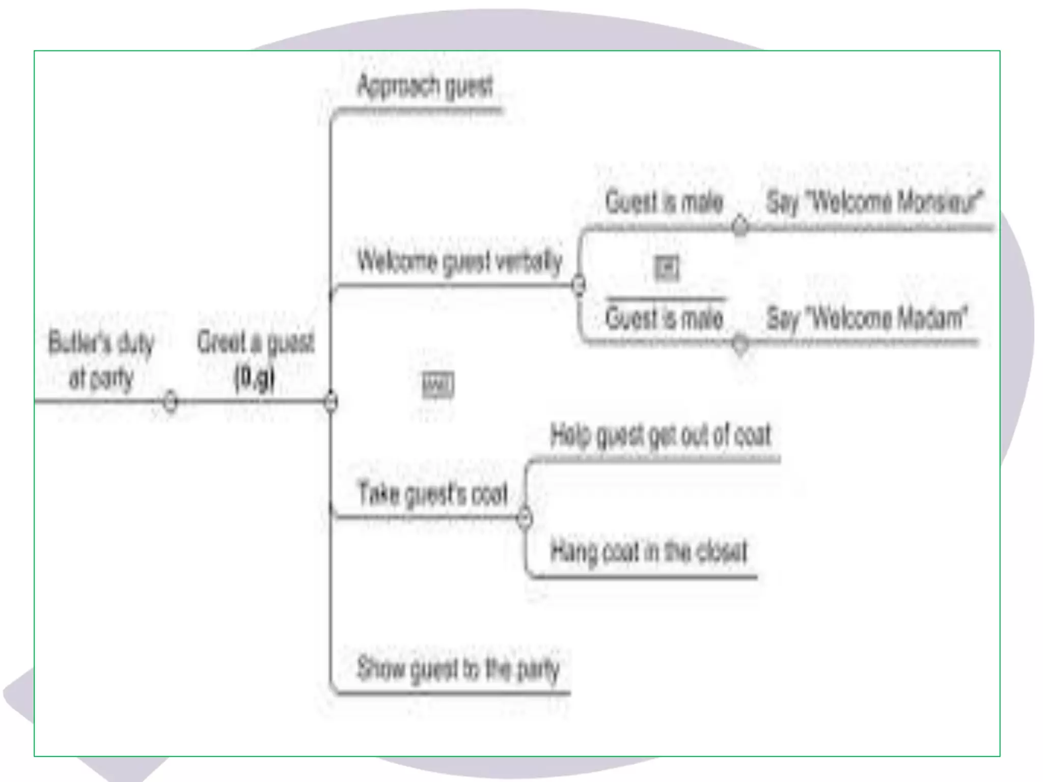
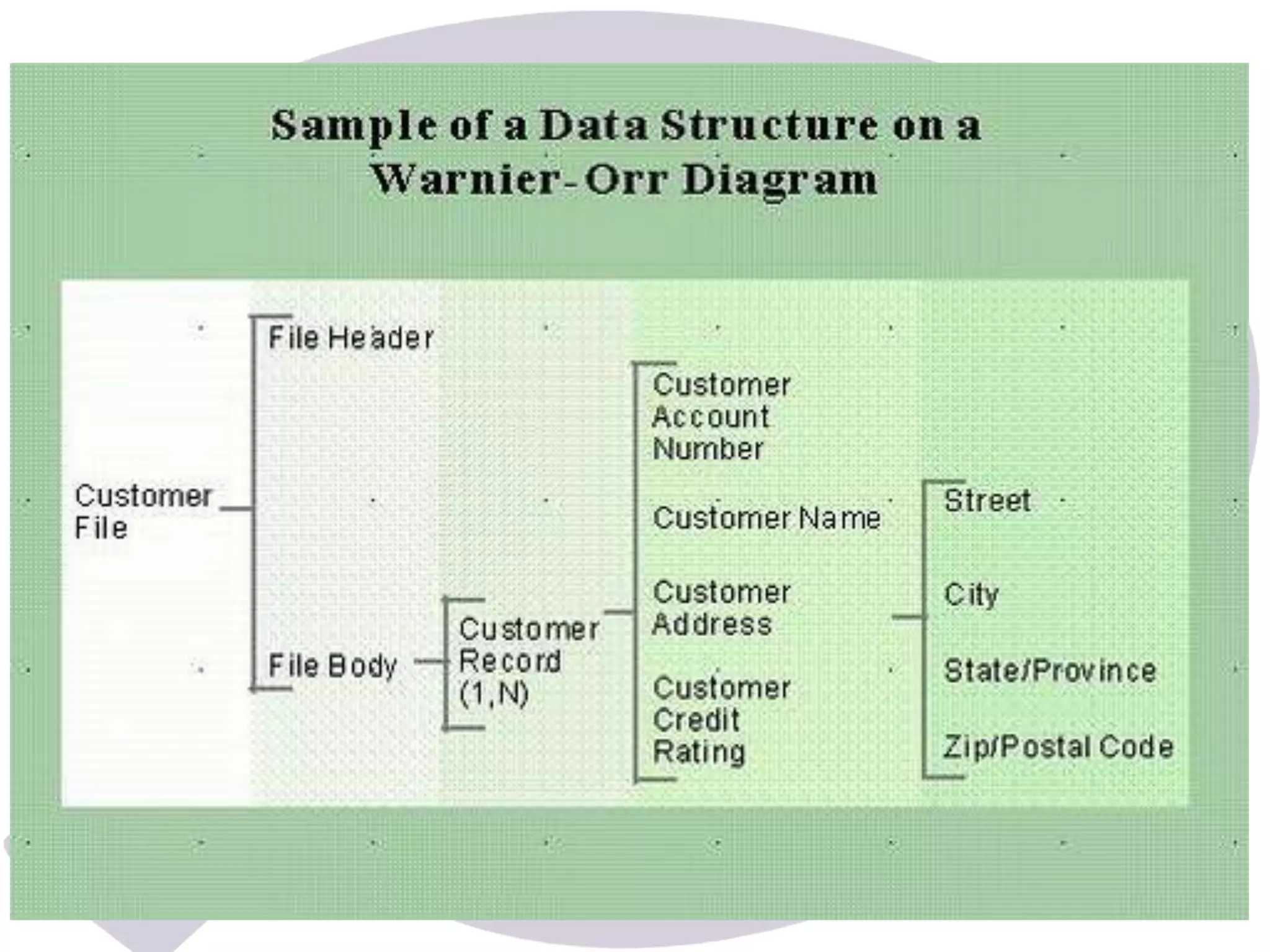
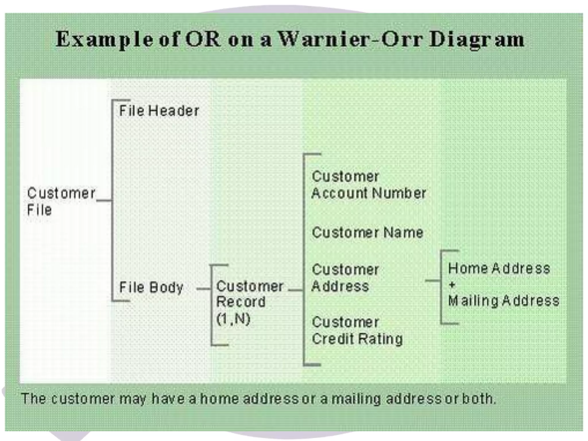
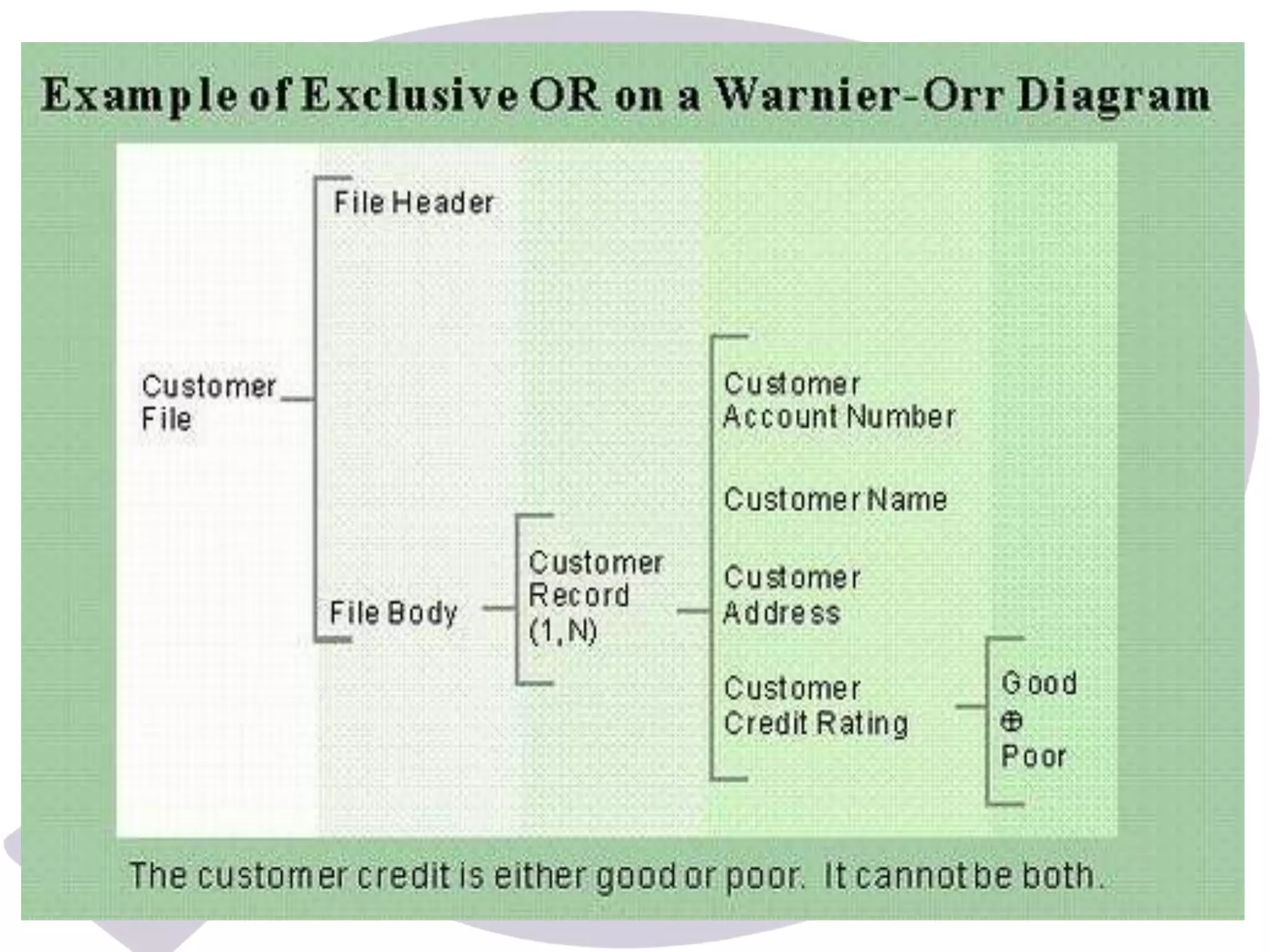
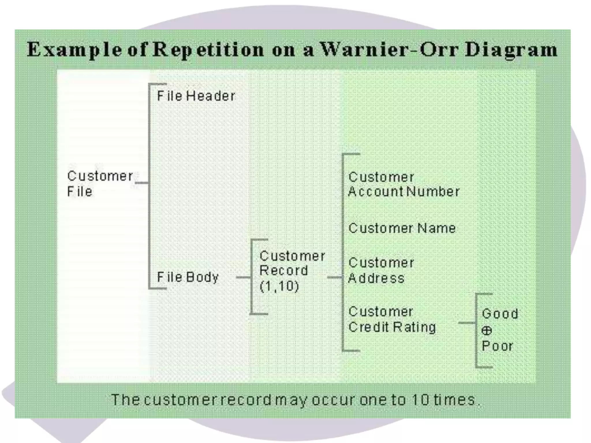
A Warnier-Orr diagram (also known as a logical 
construction of a program/system) is a kind of hierarchical 
flowchart that allows the description of the organization of 
data and procedures. 
 They were initially developed in France by Jean-Dominique 
Warnier and in the United States by Kenneth Orr. 
 This method aids the design of program structures by 
identifying the output and processing results and then 
.
 The simple graphic method used in Warnier/Orr 
diagrams makes the levels in the 
Warnier/Orr diagrams show the processes and 
sequences in which they are performed. Each 
process is defined in a hierarchical manner i.e. it 
consists of sets of sub processes that define it. At 
each level, the process is shown in bracket that 
groups its components.
UsingWarnier/Orr Diagrams 
 To develop a Warnier/Orr diagram, the analyst works 
backwards, starting with and using output 
oriented analysis. 
 On paper, the development moves from right to left. First, 
the intended output or results of the processing are 
defined. 
 At the next level, shown by inclusion with a bracket, the 
. Each step 
in turn is further defined. 
the result on the next level.
Advantages of Warnier/Orr diagram 
According to Experts: 
 They are 
. Yet they are powerful design tools. 
that 
must be passed from level to level. 
 In addition, the sequence of working backwards 
. This 
method is useful for both data and process 
definition.
Basic Constructs in 
Warnier-Orr diagram 
There are four basic constructs used on 
Warnier/Orr diagrams: 
. 
 There are also two slightly more advanced 
concepts that are occasionally needed: 
concurrency and recursion.
Constructs in Warnier-Orr Diagrams 
Hierarchy 
Hierarchy is the most fundamental of all of the Warnier- 
Orr constructs. It is simply a nested group of sets and 
subsets shown as a set of nested brackets. 
Each bracket on the diagram (depending on how you 
represent it, the character is usually more like a brace 
"{" than a bracket "[", but we call them "brackets") 
represents one level of hierarchy.
Sequence 
 Sequence 
Within one level of hierarchy, 
the features listed are shown in the order in which they 
occur. 
 In other words, the step listed first is the first that will 
be executed (if the diagram reflects a process), while 
the step listed last is the last that will be executed. 
 Similarly with data, the data field listed first is the first 
that is encountered when looking at the data, the data 
field listed last is the final one encountered.
Repetition 
Repetition is the representation of a classic 
"loop" in programming terms. 
 It occurs whenever the same set of data occurs 
over and over again ( ) or 
whenever the same group of actions is to occur 
over and over again ( ). 
Repetition is 
beneath the 
repeating set.
Alternation 
Alternation, or selection, is the traditional 
"decision" process whereby a determination is 
made to execute one process or another. 
This diagram indicates that an Employee is either 
one 
Employee cannot be both. 
 It is also permissible to use a "negation bar" 
above an alternative in a manner similar to 
engineering notation.
Concurrency 
Concurrency is one of the two advanced 
constructs used in the methodology. 
It is used whenever sequence is unimportant. 
For instance, years and weeks operate 
concurrently (or at the same time) within our 
calendar.
Recursion 
Recursion is the least used of the constructs. It is 
used to indicate that a set contains an earlier or a 
less ordered version of itself. 
 In the classic "bill of materials" problem 
components contain parts and other sub-components. 
Sub-components also contain sub-sub-components, 
and so on. The doubled bracket 
indicates that the set is recursive. Data structures 
that are truly recursive are rather rare
 A Nassi–Shneiderman diagram (NSD) in 
computer programming is a graphical 
design representation for structured 
programming . 
 This type of diagram was developed in 1972 
by who were 
both graduate students at SUNY-Stony Brook.
 Nassi–Shneiderman diagrams are (almost) 
isomorphic with flowcharts. 
 Everything you can represent with a 
 For flowcharts of programs, almost everything 
you can represent with a flowchart you can also 
represent with a Nassi–Shneiderman diagram.
Process 
A process describes a program function as 
pseudocode. You can stack processes on top of each 
other to illustrate a sequence.
Parallel Process 
Place processes that are executed at the same time 
inside a trapezium created by drawing two diagonal lines in 
the upper and lower border of the table.
Repeated Process (Loop) 
 Use loop notations when processes are repeated until a 
certain condition is met.
Decision 
 The selection symbol is a rectangle divided into three parts 
by diagonal lines. 
 Write the condition or decision in the uppermost triangle 
and place the two possible outcomes on either side of the 
decision. The two outcomes don't need to be the same 
size.
Case statement 
List multiple cases next to each other in a 
table format.
 A decision tree is a decision support tool 
that uses a tree-like graph or model of 
decisions and their possible 
consequences, including chance event 
outcomes, resource costs, and utility.
 It is a table of possibilities for defining a problem and the 
actions to be taken 
 It is a single representation of the relationships 
between conditions and actions 
 It consists of two parts: stub and entry 
 The stub part is divided into called 
the and a lower quadrant called the action 
stub 
 The entry part is also divided into an upper quadrant, 
called the condition entry and a lower quadrant called 
the action entry
modelingtools

modelingtools

  • 2.
    A Warnier-Orr diagram(also known as a logical construction of a program/system) is a kind of hierarchical flowchart that allows the description of the organization of data and procedures.  They were initially developed in France by Jean-Dominique Warnier and in the United States by Kenneth Orr.  This method aids the design of program structures by identifying the output and processing results and then .
  • 3.
     The simplegraphic method used in Warnier/Orr diagrams makes the levels in the Warnier/Orr diagrams show the processes and sequences in which they are performed. Each process is defined in a hierarchical manner i.e. it consists of sets of sub processes that define it. At each level, the process is shown in bracket that groups its components.
  • 5.
    UsingWarnier/Orr Diagrams To develop a Warnier/Orr diagram, the analyst works backwards, starting with and using output oriented analysis.  On paper, the development moves from right to left. First, the intended output or results of the processing are defined.  At the next level, shown by inclusion with a bracket, the . Each step in turn is further defined. the result on the next level.
  • 6.
    Advantages of Warnier/Orrdiagram According to Experts:  They are . Yet they are powerful design tools. that must be passed from level to level.  In addition, the sequence of working backwards . This method is useful for both data and process definition.
  • 7.
    Basic Constructs in Warnier-Orr diagram There are four basic constructs used on Warnier/Orr diagrams: .  There are also two slightly more advanced concepts that are occasionally needed: concurrency and recursion.
  • 8.
    Constructs in Warnier-OrrDiagrams Hierarchy Hierarchy is the most fundamental of all of the Warnier- Orr constructs. It is simply a nested group of sets and subsets shown as a set of nested brackets. Each bracket on the diagram (depending on how you represent it, the character is usually more like a brace "{" than a bracket "[", but we call them "brackets") represents one level of hierarchy.
  • 9.
    Sequence  Sequence Within one level of hierarchy, the features listed are shown in the order in which they occur.  In other words, the step listed first is the first that will be executed (if the diagram reflects a process), while the step listed last is the last that will be executed.  Similarly with data, the data field listed first is the first that is encountered when looking at the data, the data field listed last is the final one encountered.
  • 10.
    Repetition Repetition isthe representation of a classic "loop" in programming terms.  It occurs whenever the same set of data occurs over and over again ( ) or whenever the same group of actions is to occur over and over again ( ). Repetition is beneath the repeating set.
  • 11.
    Alternation Alternation, orselection, is the traditional "decision" process whereby a determination is made to execute one process or another. This diagram indicates that an Employee is either one Employee cannot be both.  It is also permissible to use a "negation bar" above an alternative in a manner similar to engineering notation.
  • 12.
    Concurrency Concurrency isone of the two advanced constructs used in the methodology. It is used whenever sequence is unimportant. For instance, years and weeks operate concurrently (or at the same time) within our calendar.
  • 13.
    Recursion Recursion isthe least used of the constructs. It is used to indicate that a set contains an earlier or a less ordered version of itself.  In the classic "bill of materials" problem components contain parts and other sub-components. Sub-components also contain sub-sub-components, and so on. The doubled bracket indicates that the set is recursive. Data structures that are truly recursive are rather rare
  • 21.
     A Nassi–Shneidermandiagram (NSD) in computer programming is a graphical design representation for structured programming .  This type of diagram was developed in 1972 by who were both graduate students at SUNY-Stony Brook.
  • 22.
     Nassi–Shneiderman diagramsare (almost) isomorphic with flowcharts.  Everything you can represent with a  For flowcharts of programs, almost everything you can represent with a flowchart you can also represent with a Nassi–Shneiderman diagram.
  • 23.
    Process A processdescribes a program function as pseudocode. You can stack processes on top of each other to illustrate a sequence.
  • 24.
    Parallel Process Placeprocesses that are executed at the same time inside a trapezium created by drawing two diagonal lines in the upper and lower border of the table.
  • 25.
    Repeated Process (Loop)  Use loop notations when processes are repeated until a certain condition is met.
  • 26.
    Decision  Theselection symbol is a rectangle divided into three parts by diagonal lines.  Write the condition or decision in the uppermost triangle and place the two possible outcomes on either side of the decision. The two outcomes don't need to be the same size.
  • 27.
    Case statement Listmultiple cases next to each other in a table format.
  • 29.
     A decisiontree is a decision support tool that uses a tree-like graph or model of decisions and their possible consequences, including chance event outcomes, resource costs, and utility.
  • 35.
     It isa table of possibilities for defining a problem and the actions to be taken  It is a single representation of the relationships between conditions and actions  It consists of two parts: stub and entry  The stub part is divided into called the and a lower quadrant called the action stub  The entry part is also divided into an upper quadrant, called the condition entry and a lower quadrant called the action entry