Download to read offline
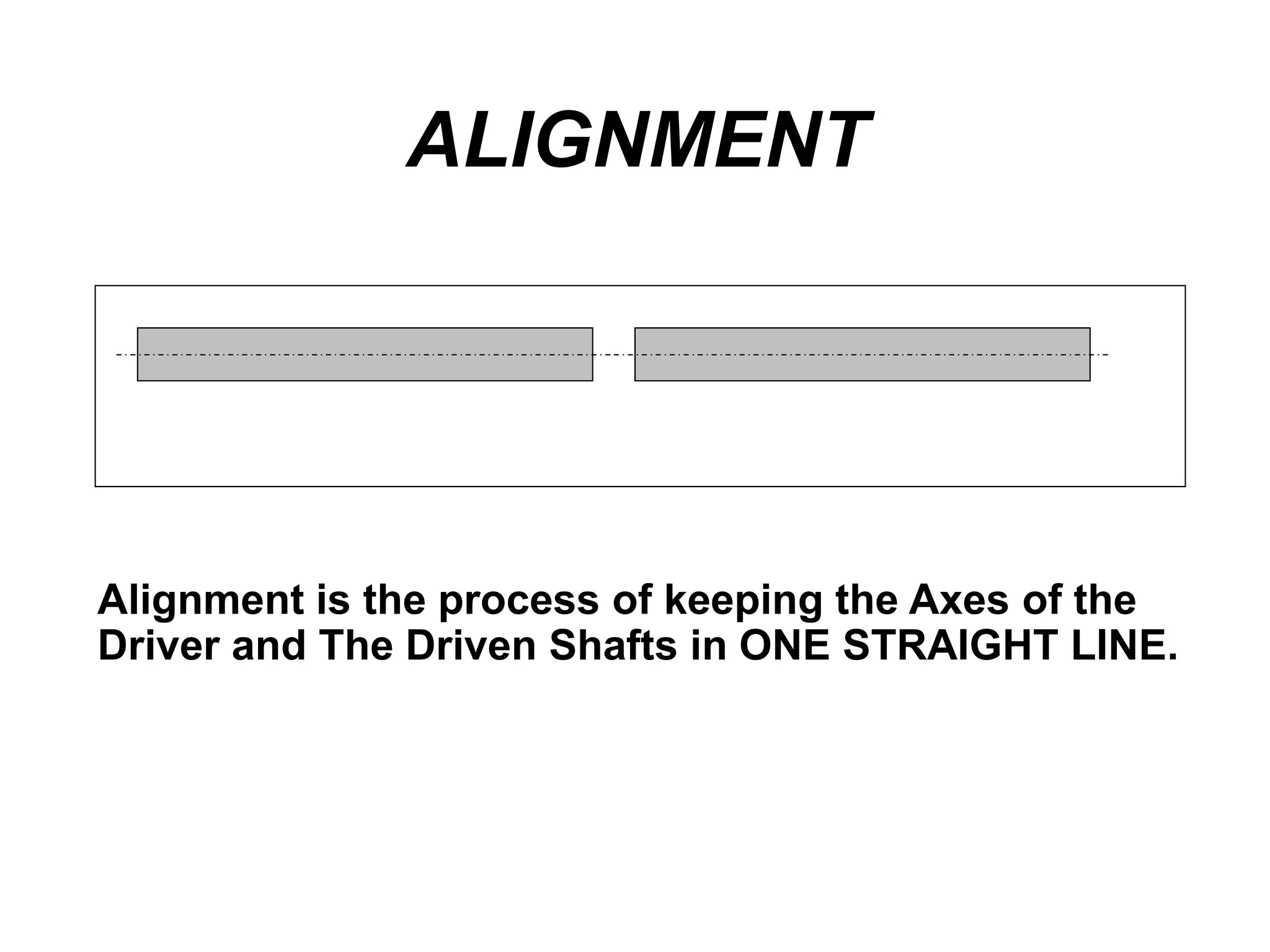
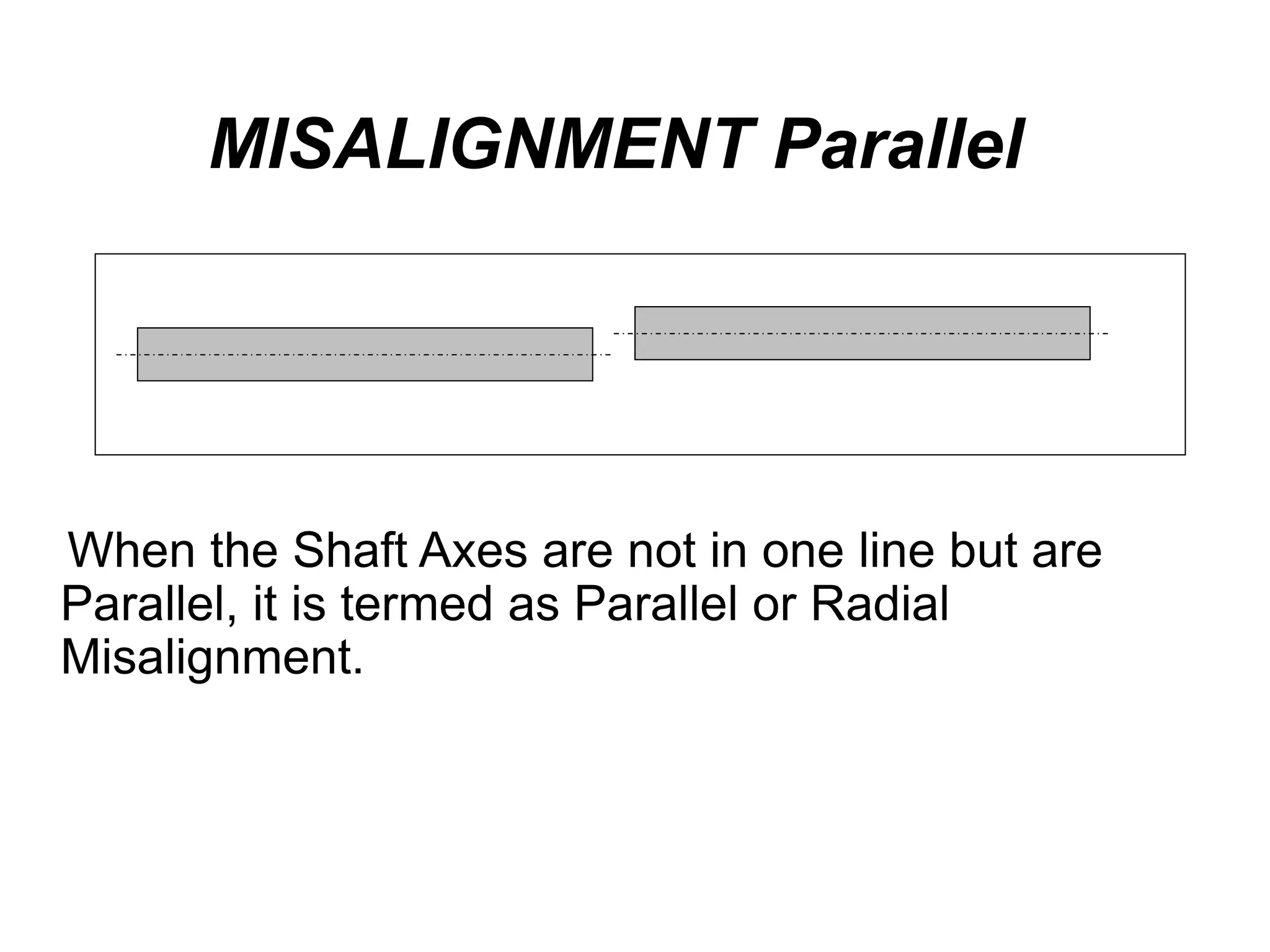
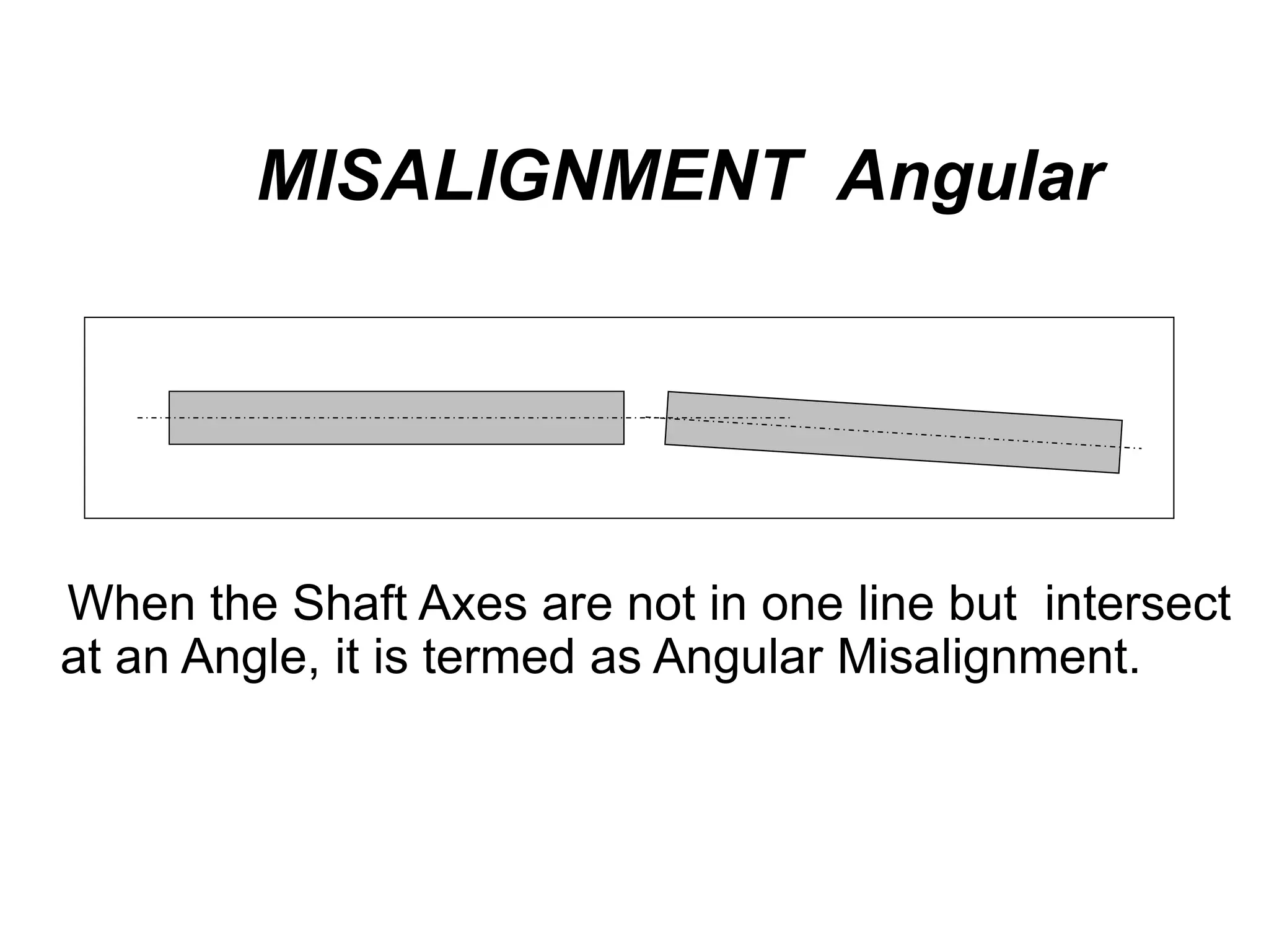
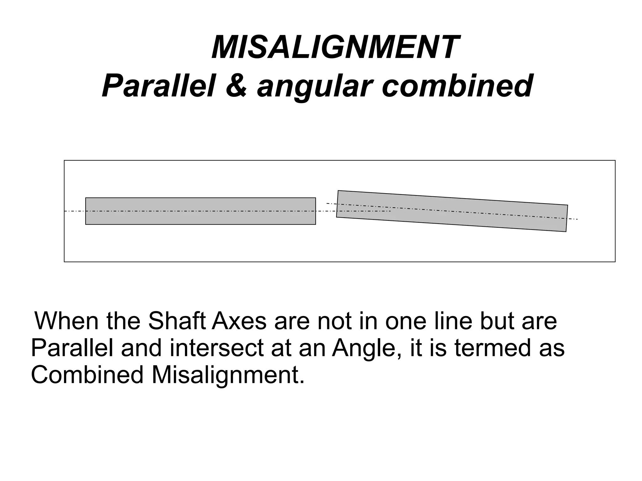
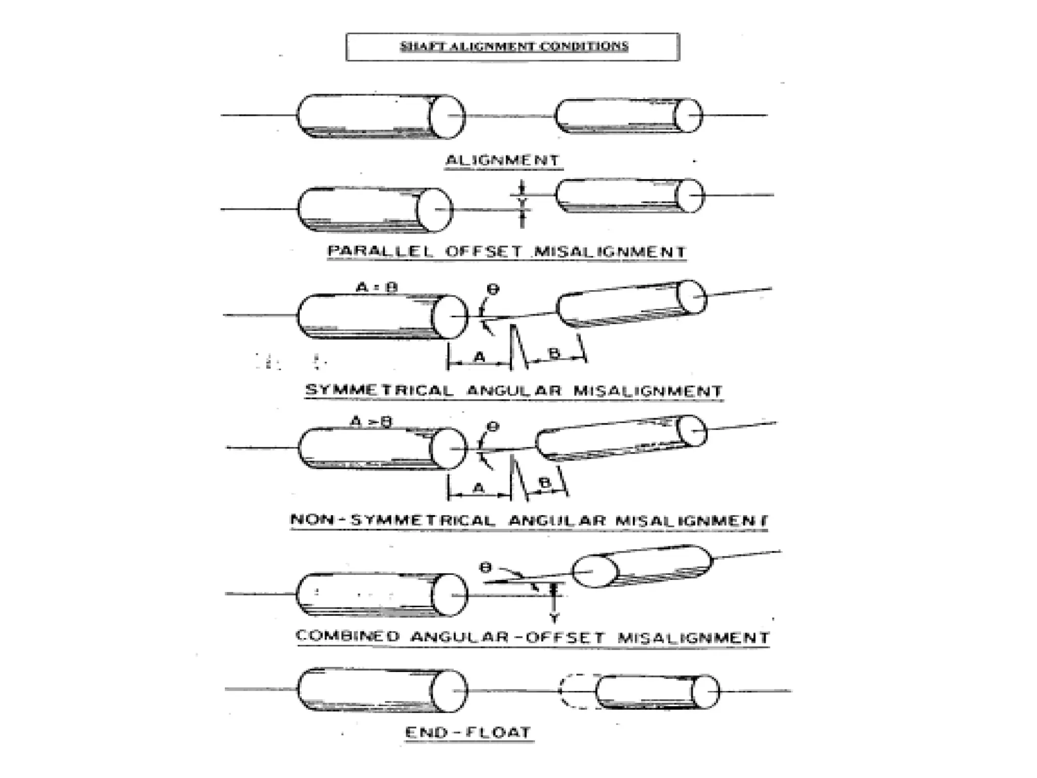
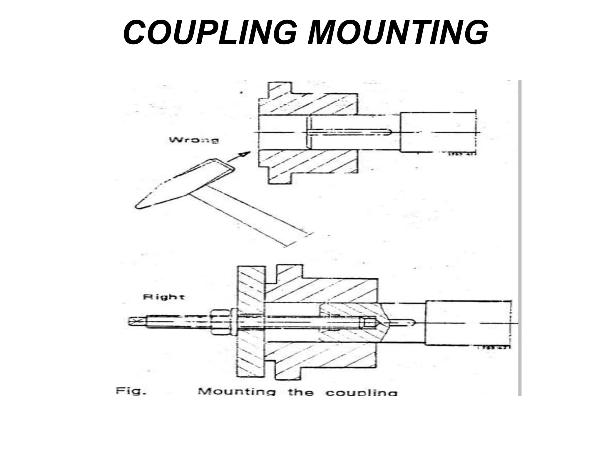
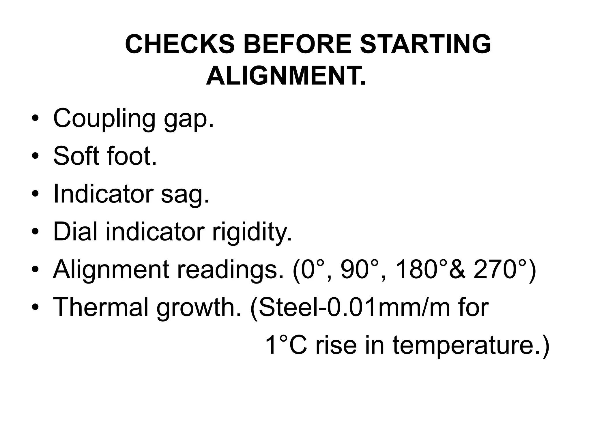
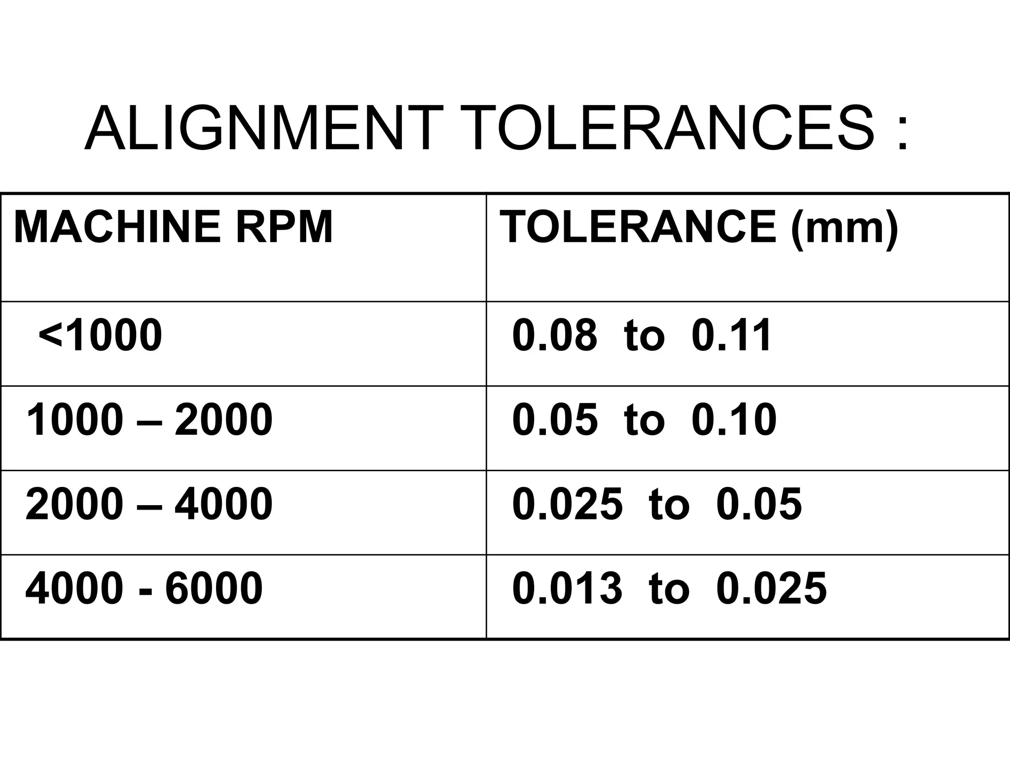
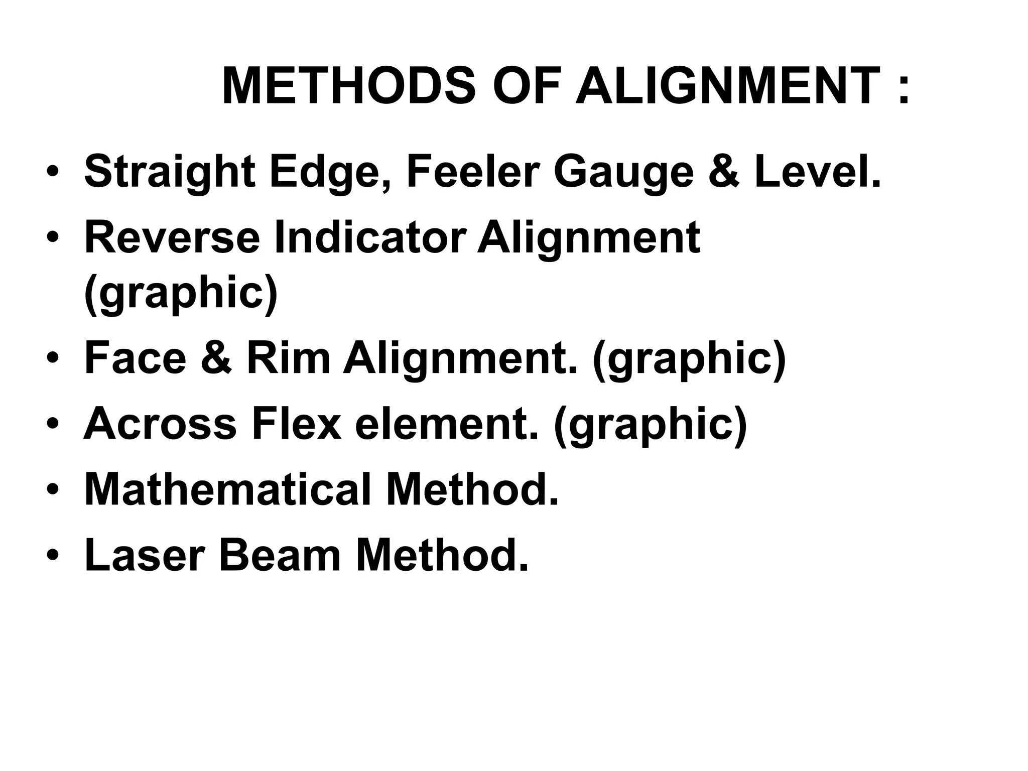
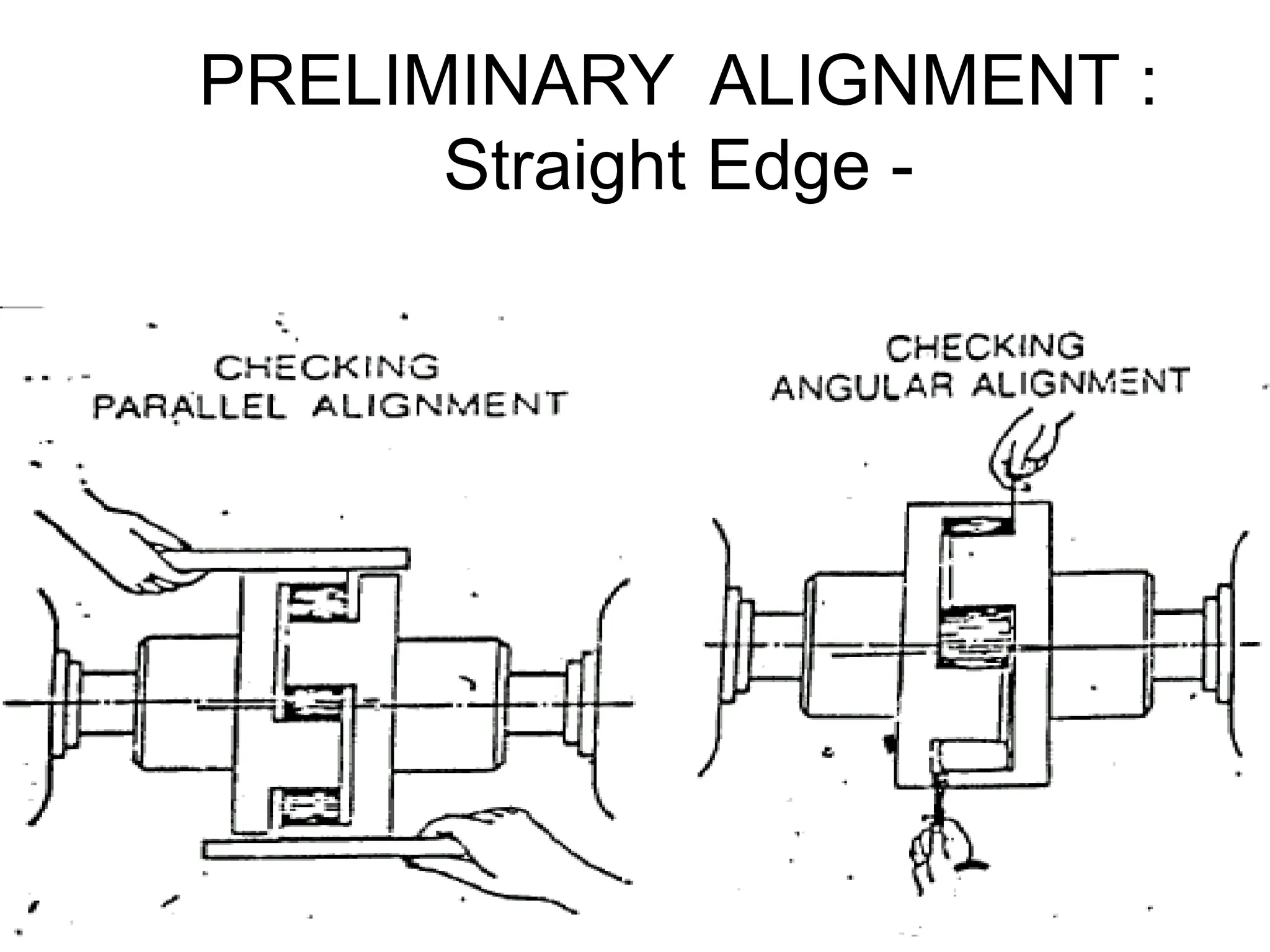
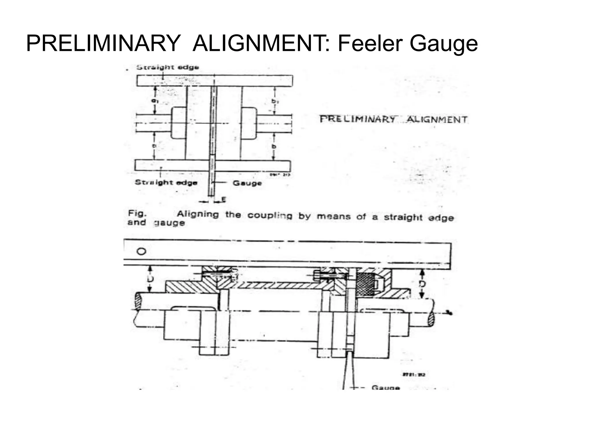
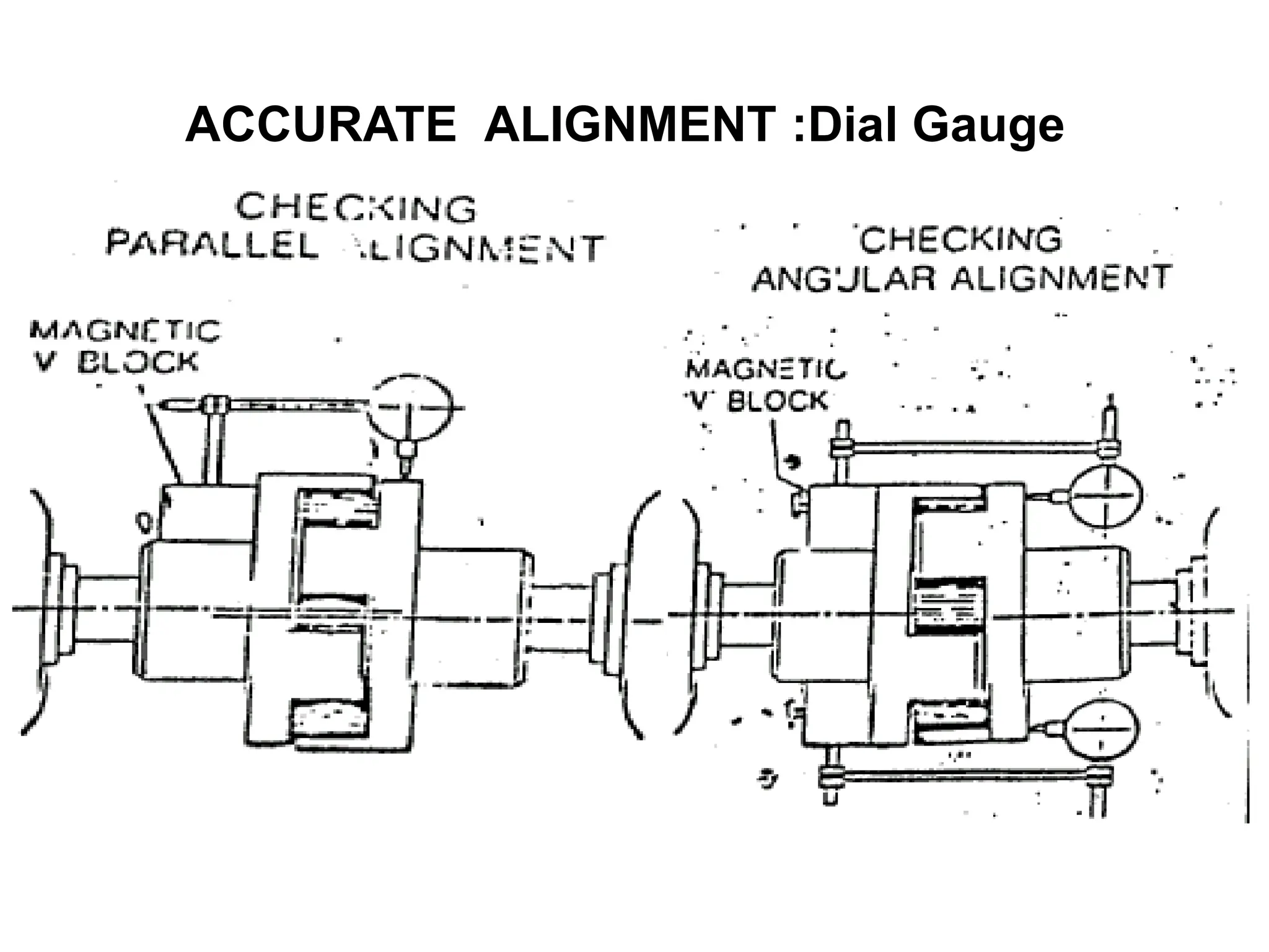
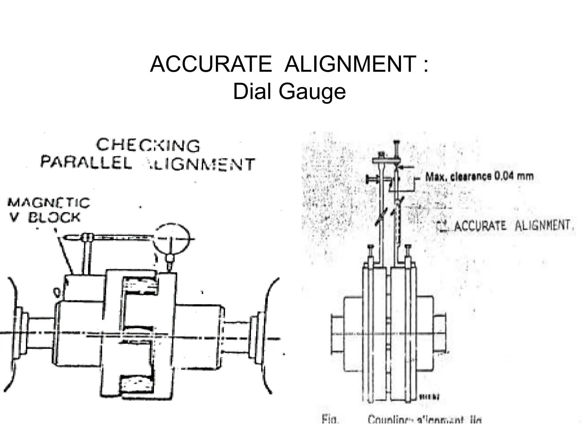
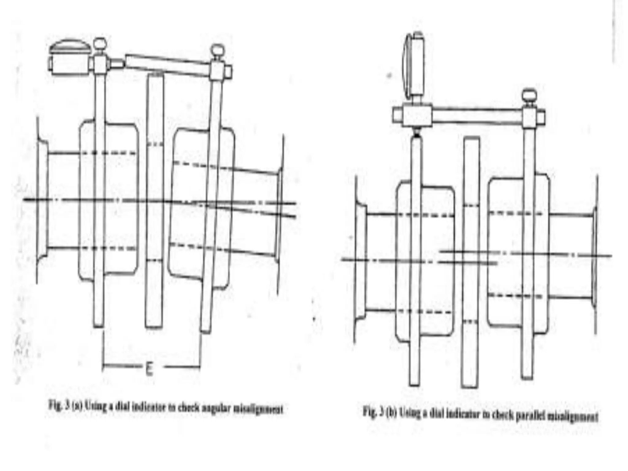
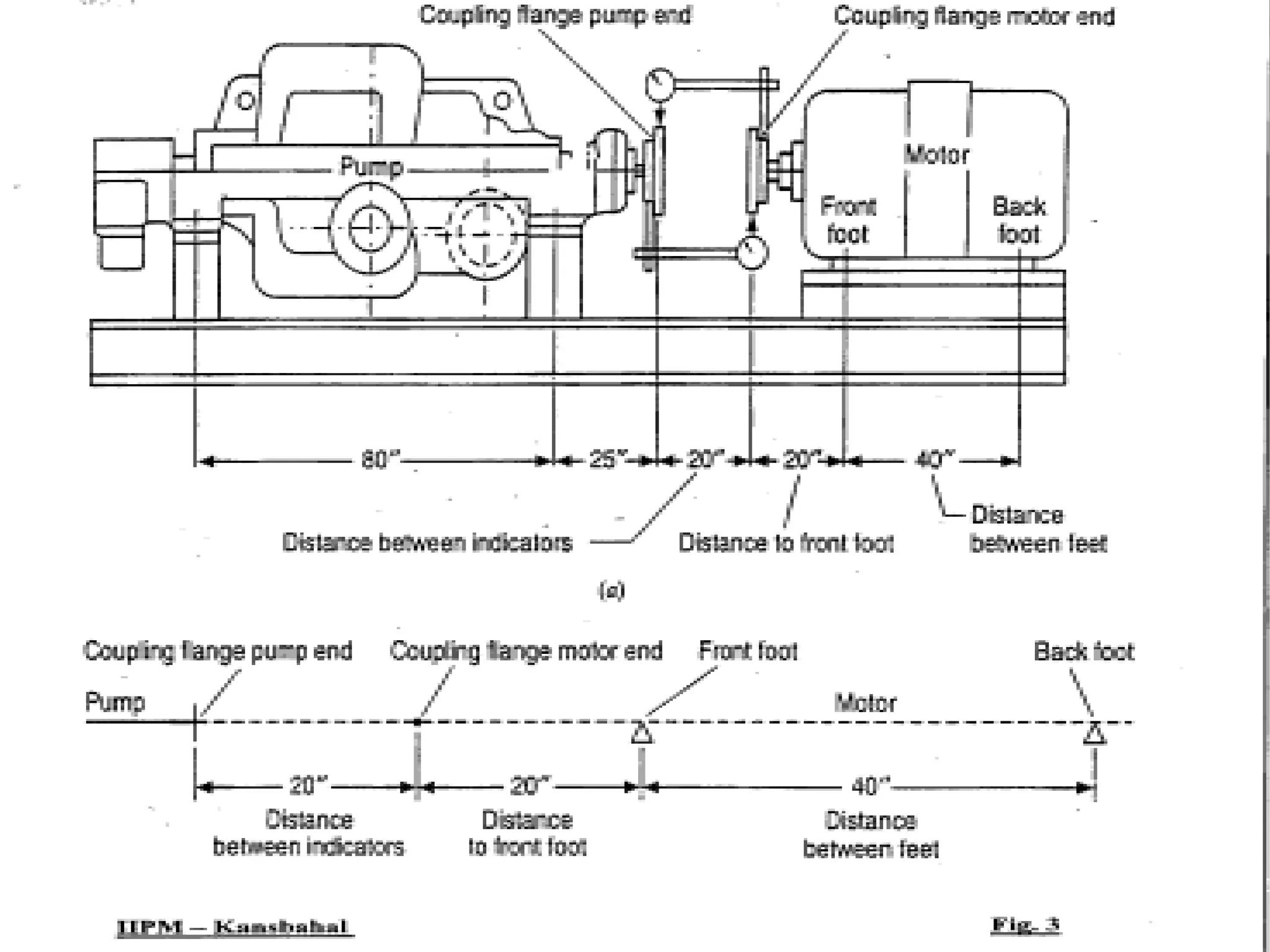
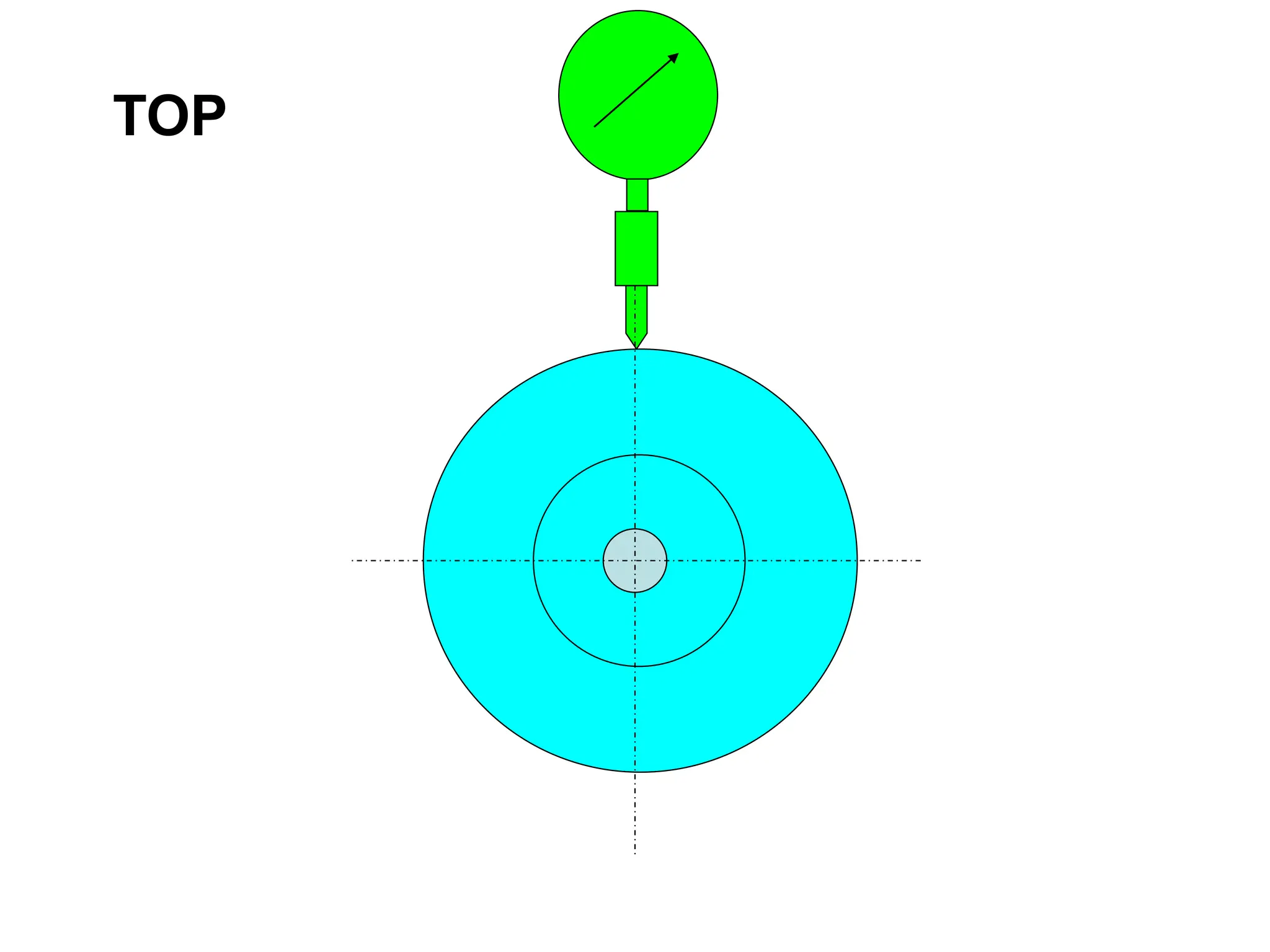
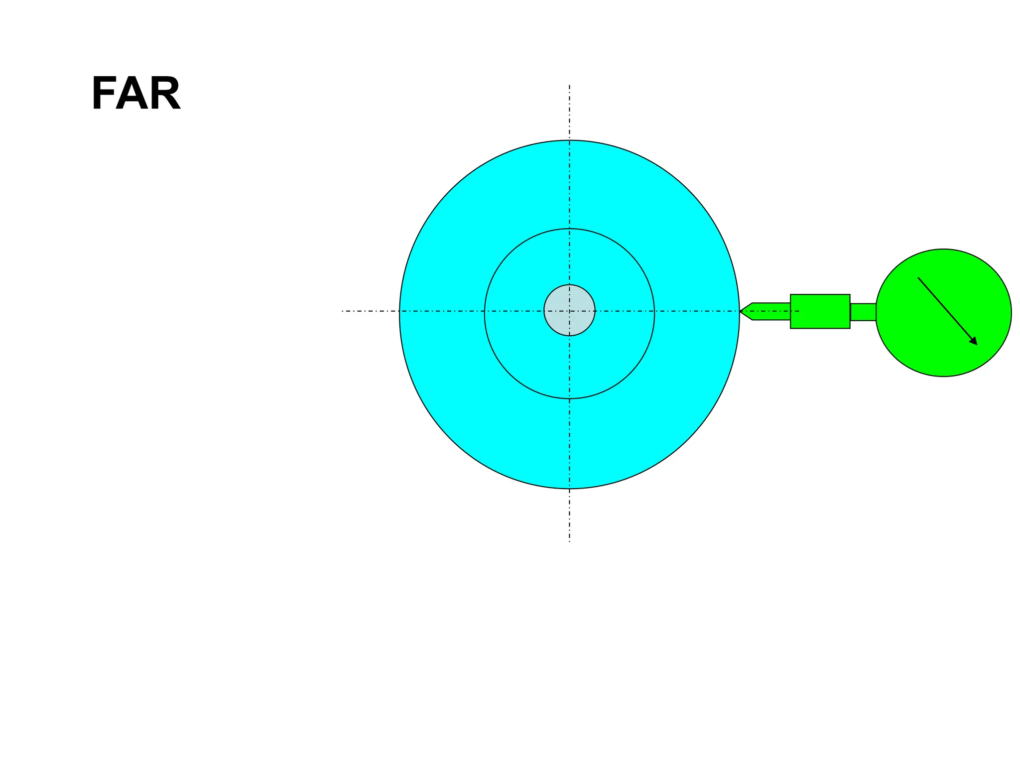
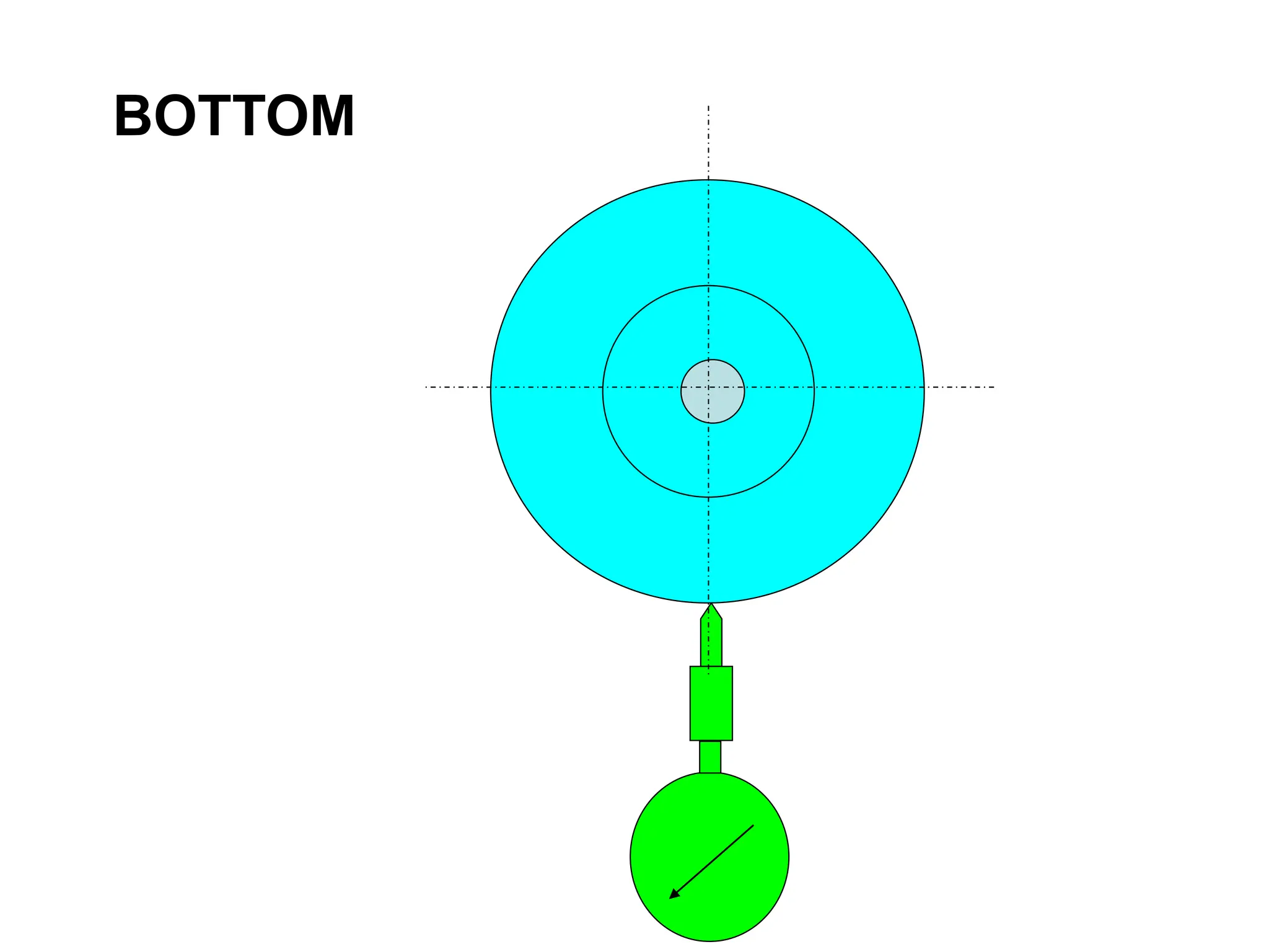
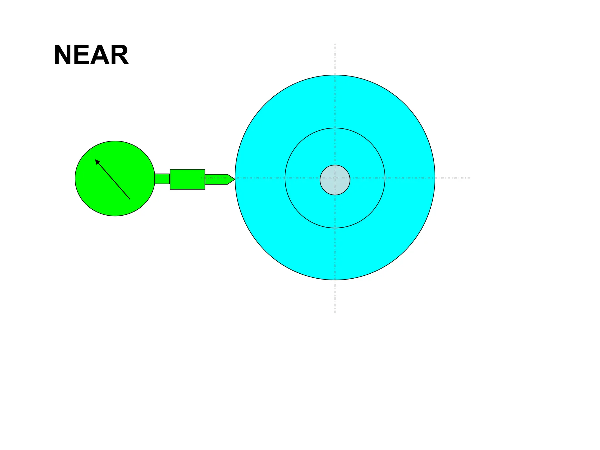
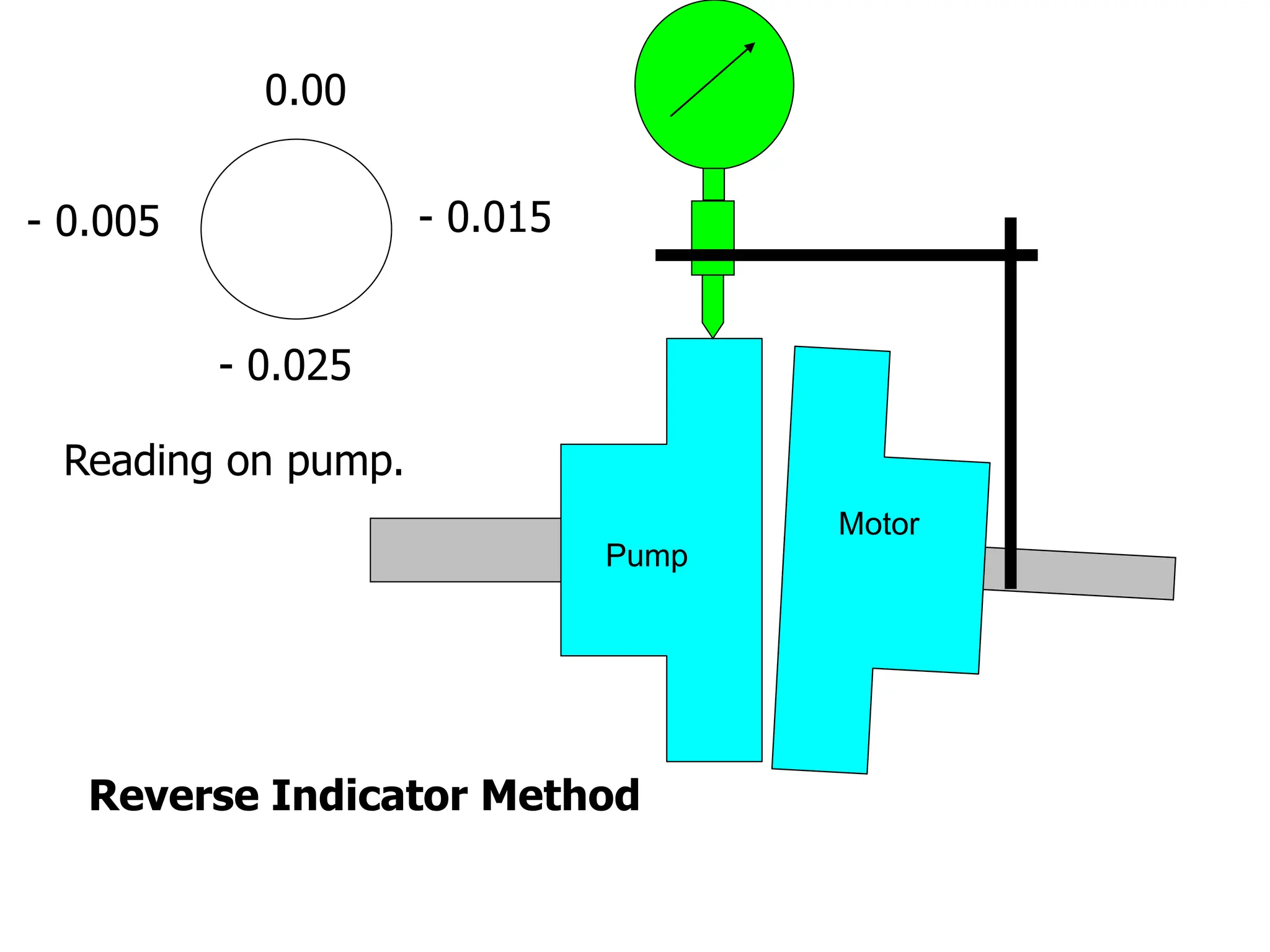
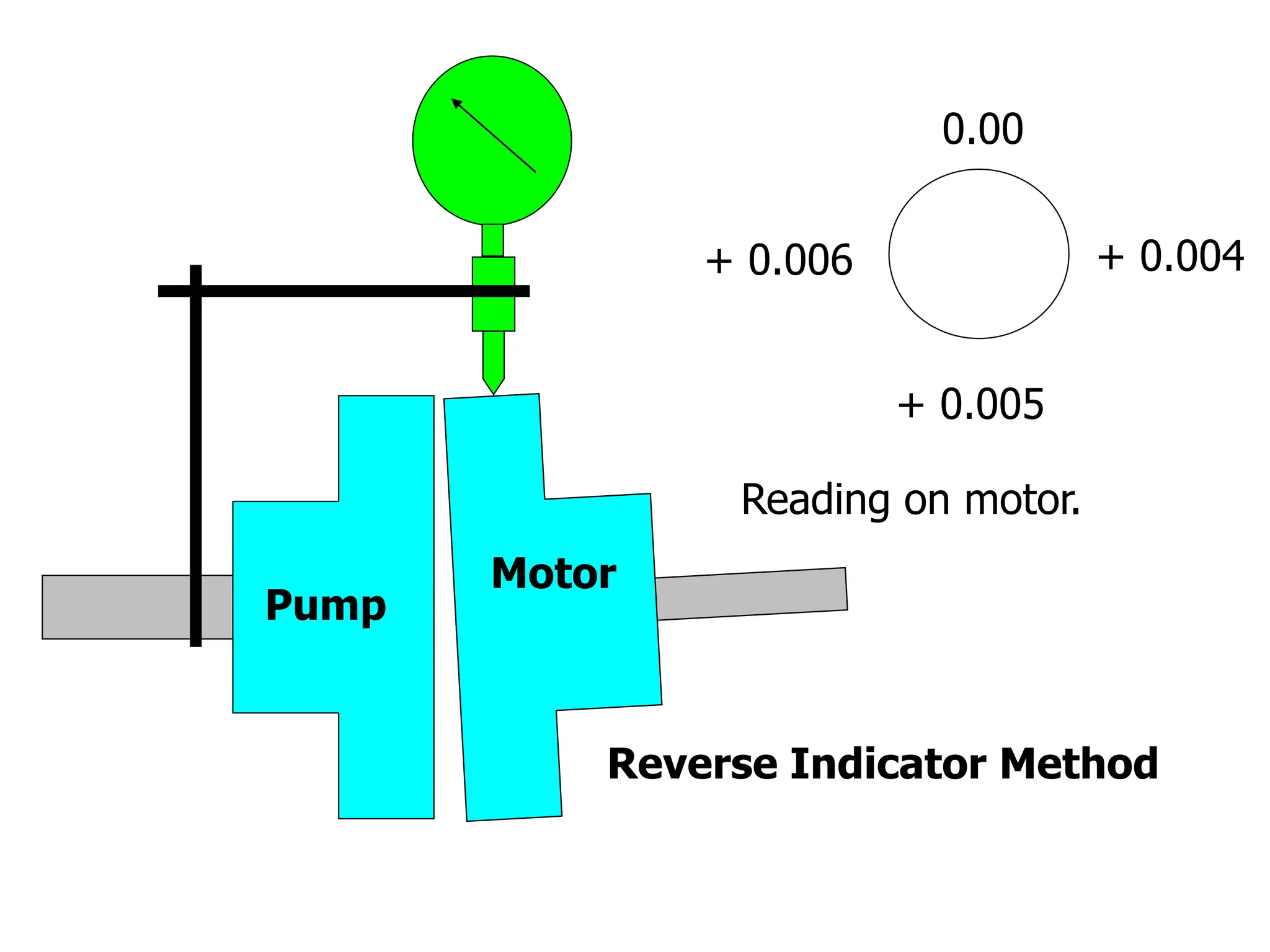


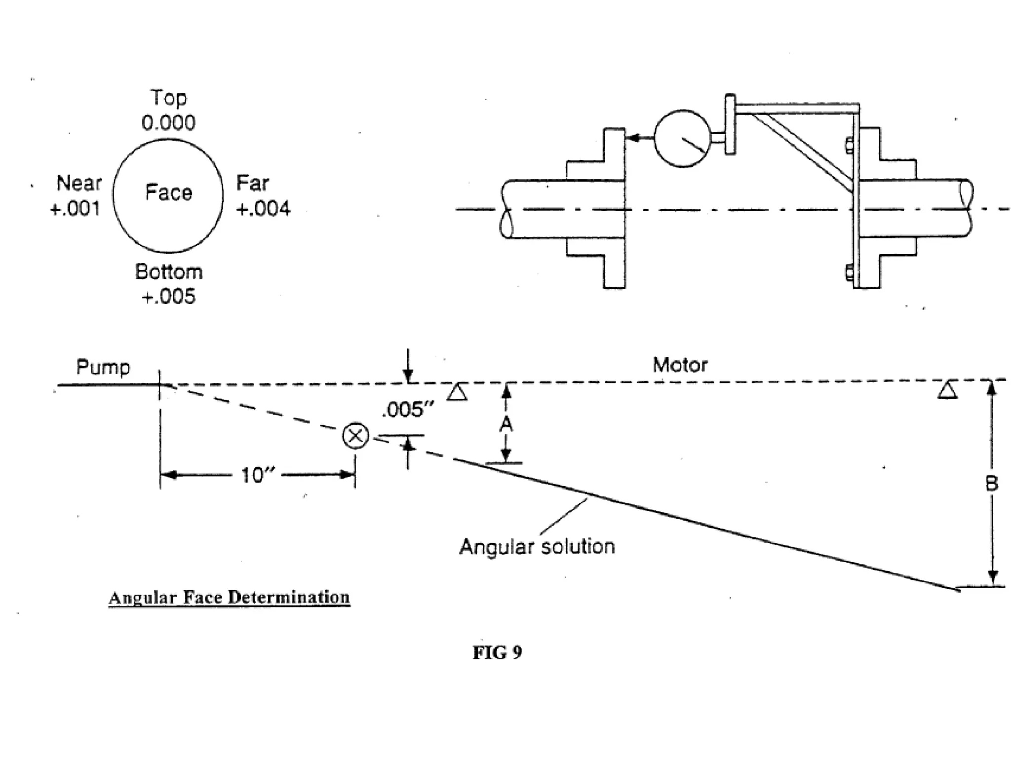
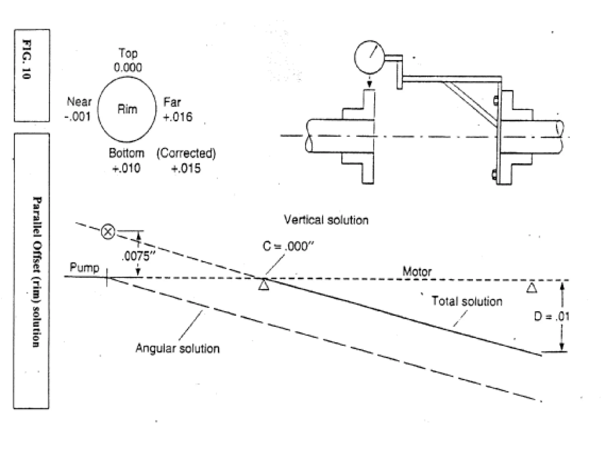

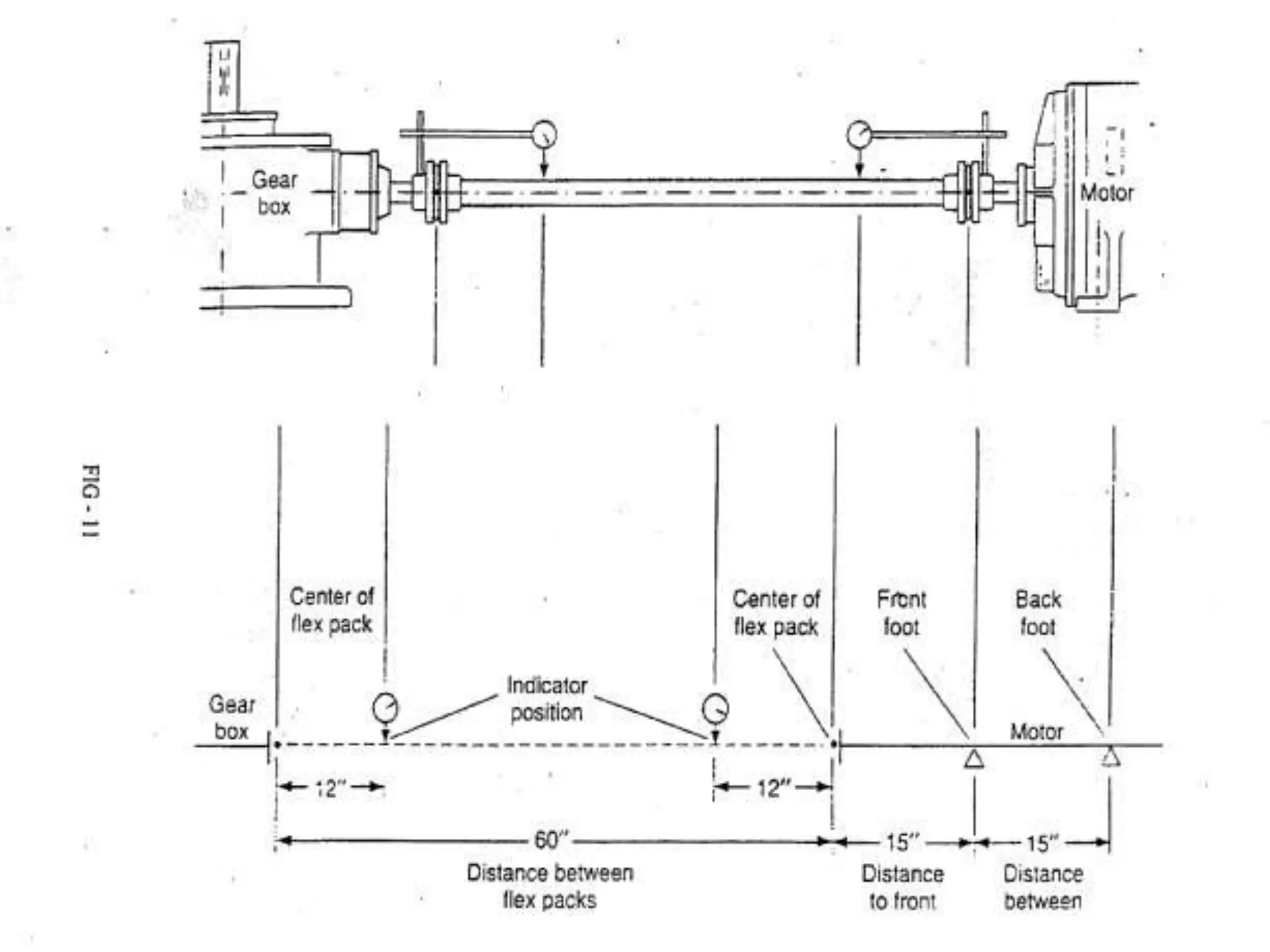
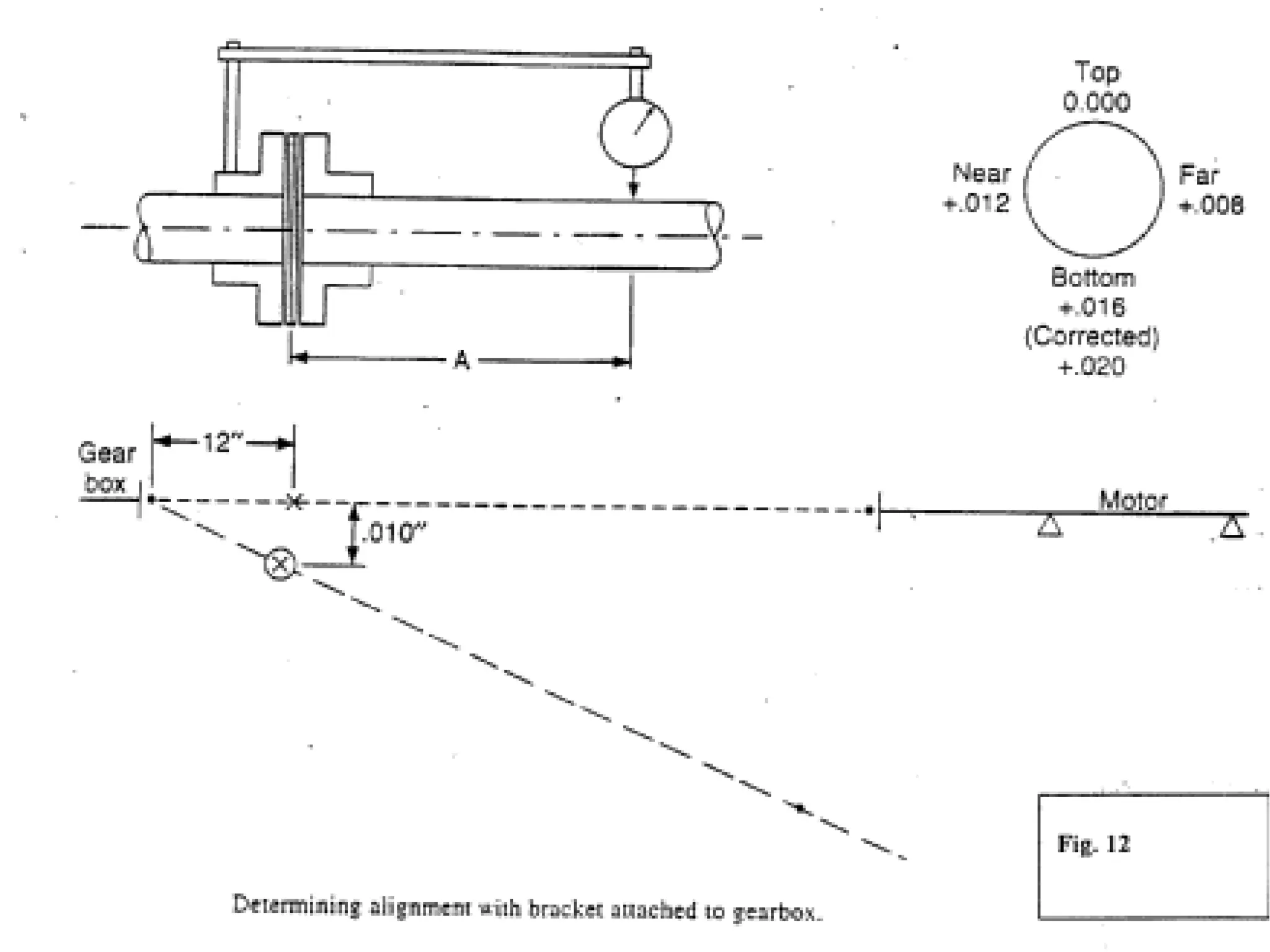


The document covers the topic of machine alignment, detailing the various types of misalignment (parallel, angular, combined) and their impact on machinery performance and vibration. It emphasizes the importance of precise alignment techniques, including checks for soft foot, indicator sag, and dial indicator rigidity, along with methods for detecting and correcting misalignment. Additionally, it discusses the consequences of misalignment on equipment failure, vibration characteristics, and provides guidelines for alignment tolerances and methods used.


![ANPARA THERMAL POWER STATION[1] sangam.pdf](https://cdn.slidesharecdn.com/ss_thumbnails/anparathermalpowerstation1sangam-251121115219-9261cde4-thumbnail.jpg?width=640&height=640&fit=bounds)


