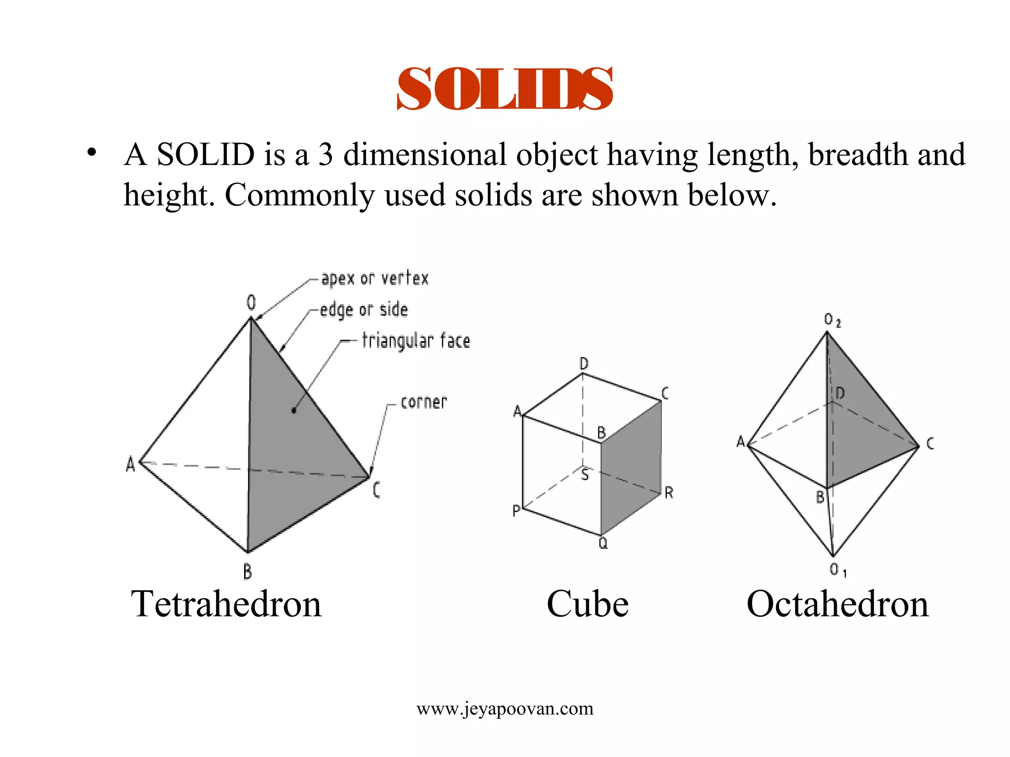
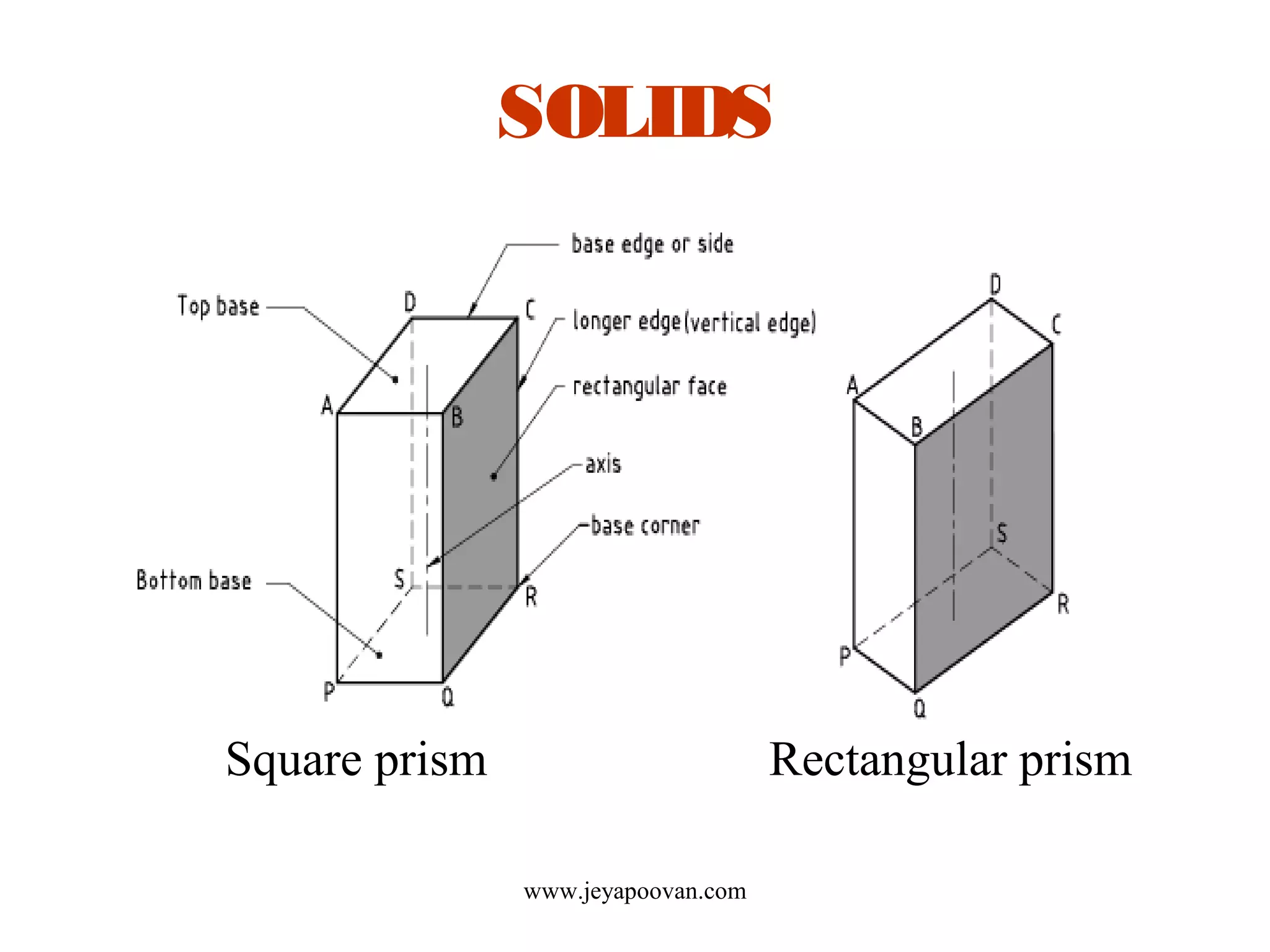
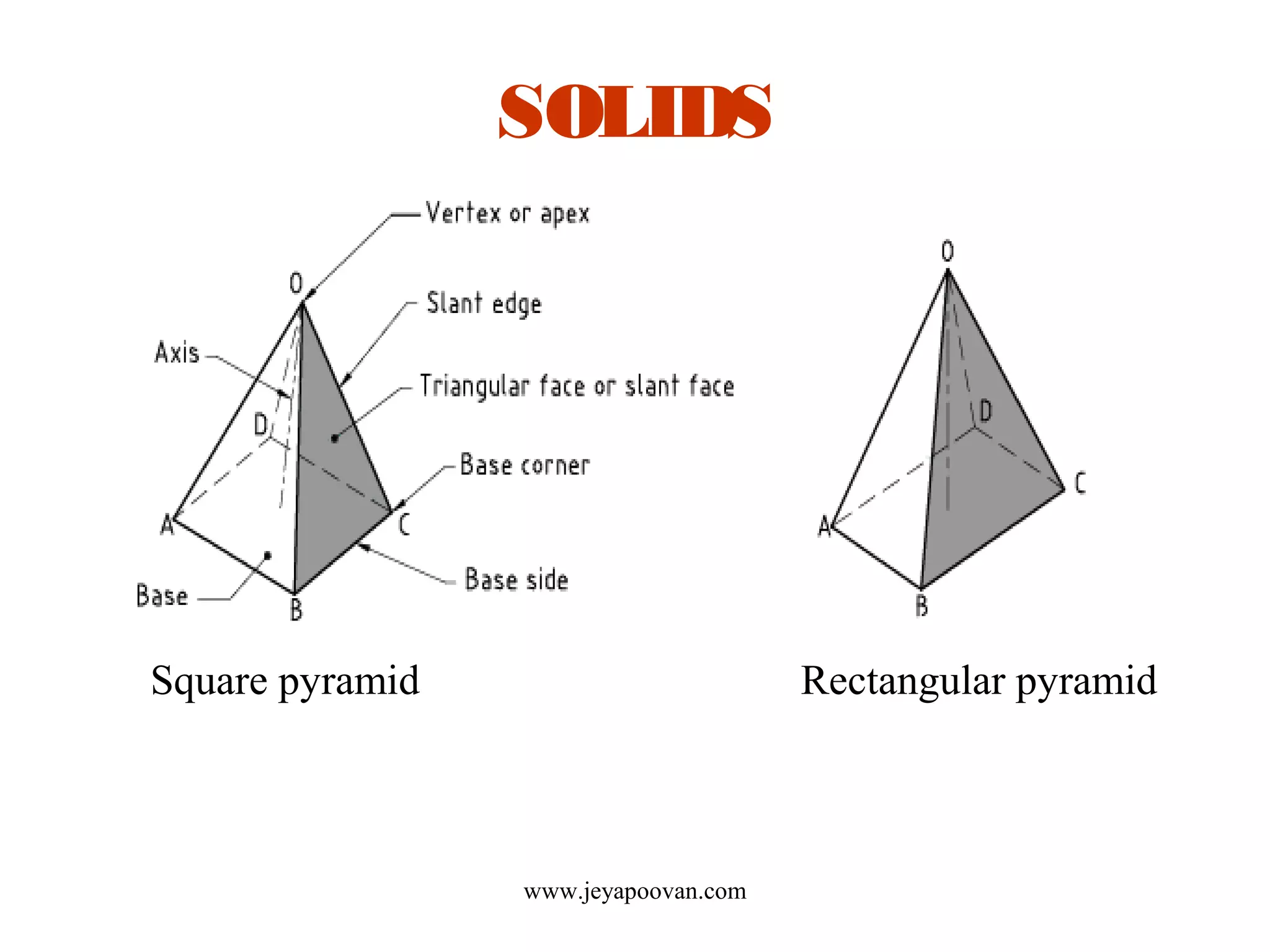
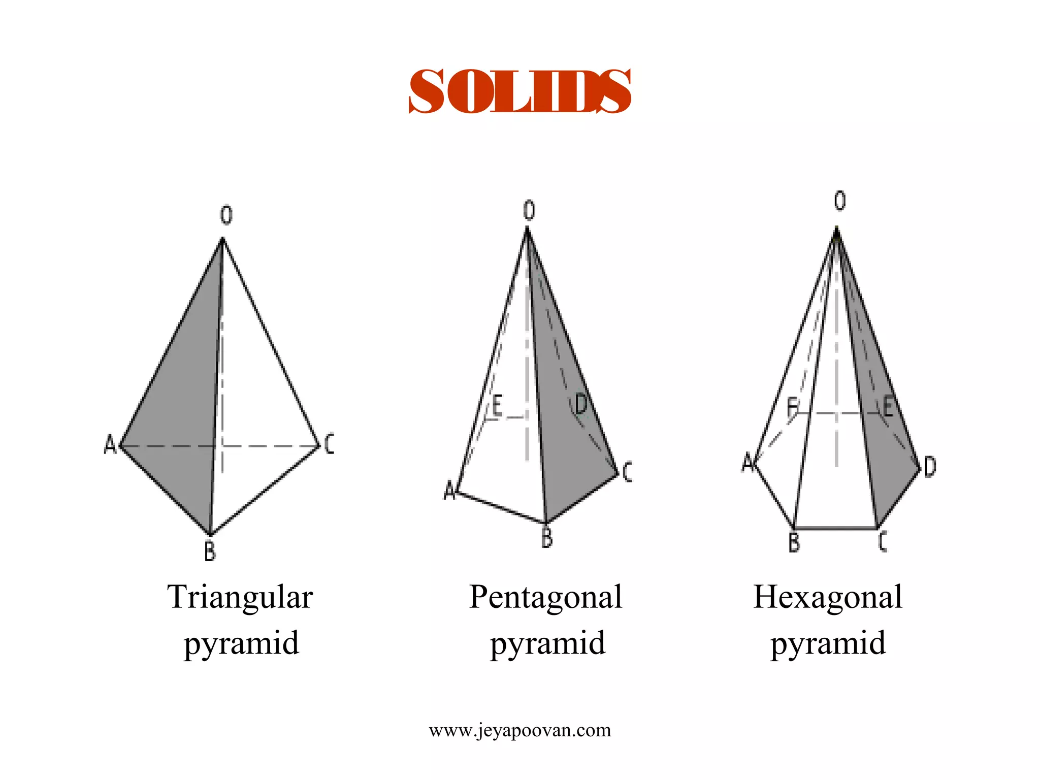
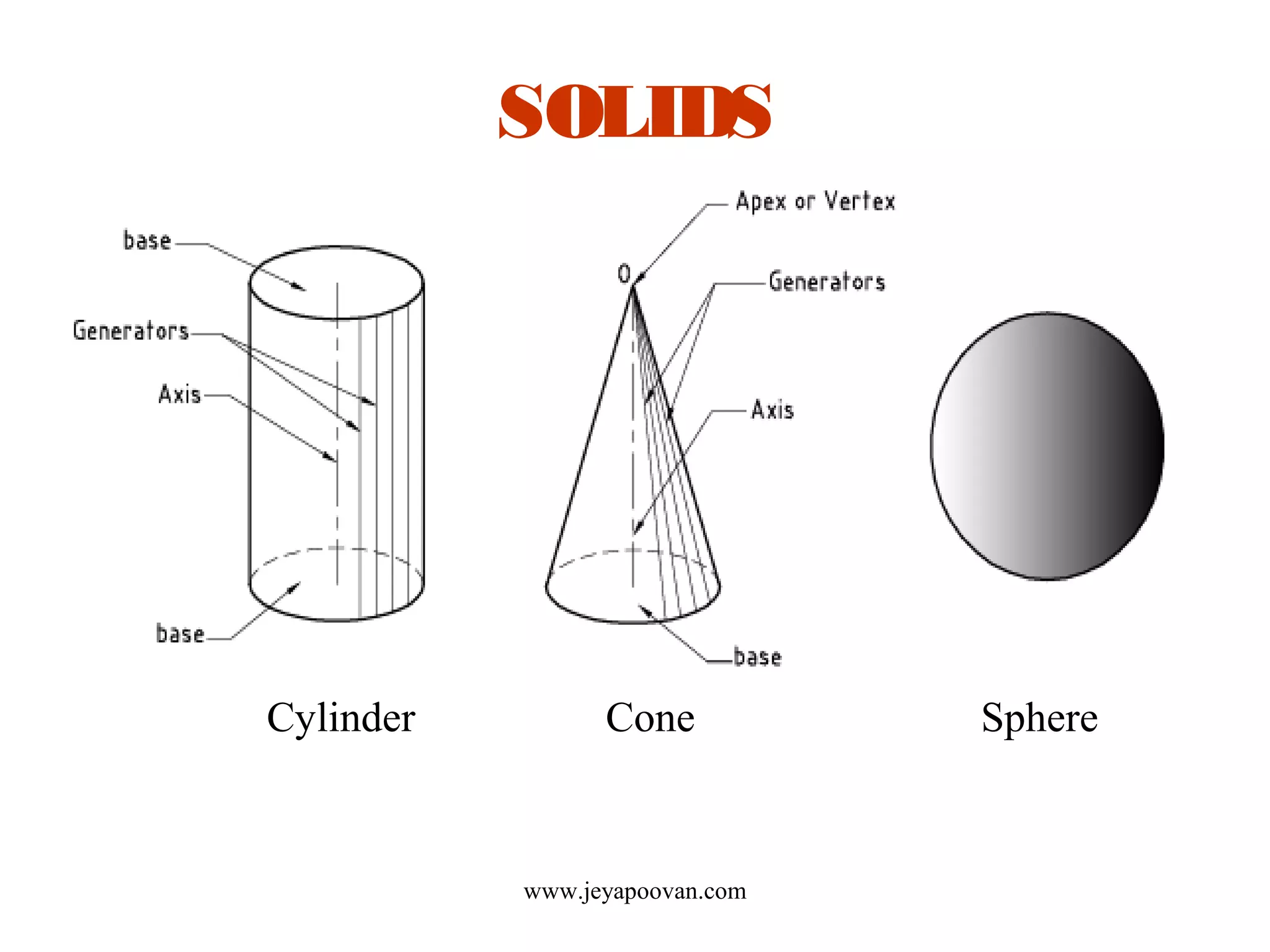
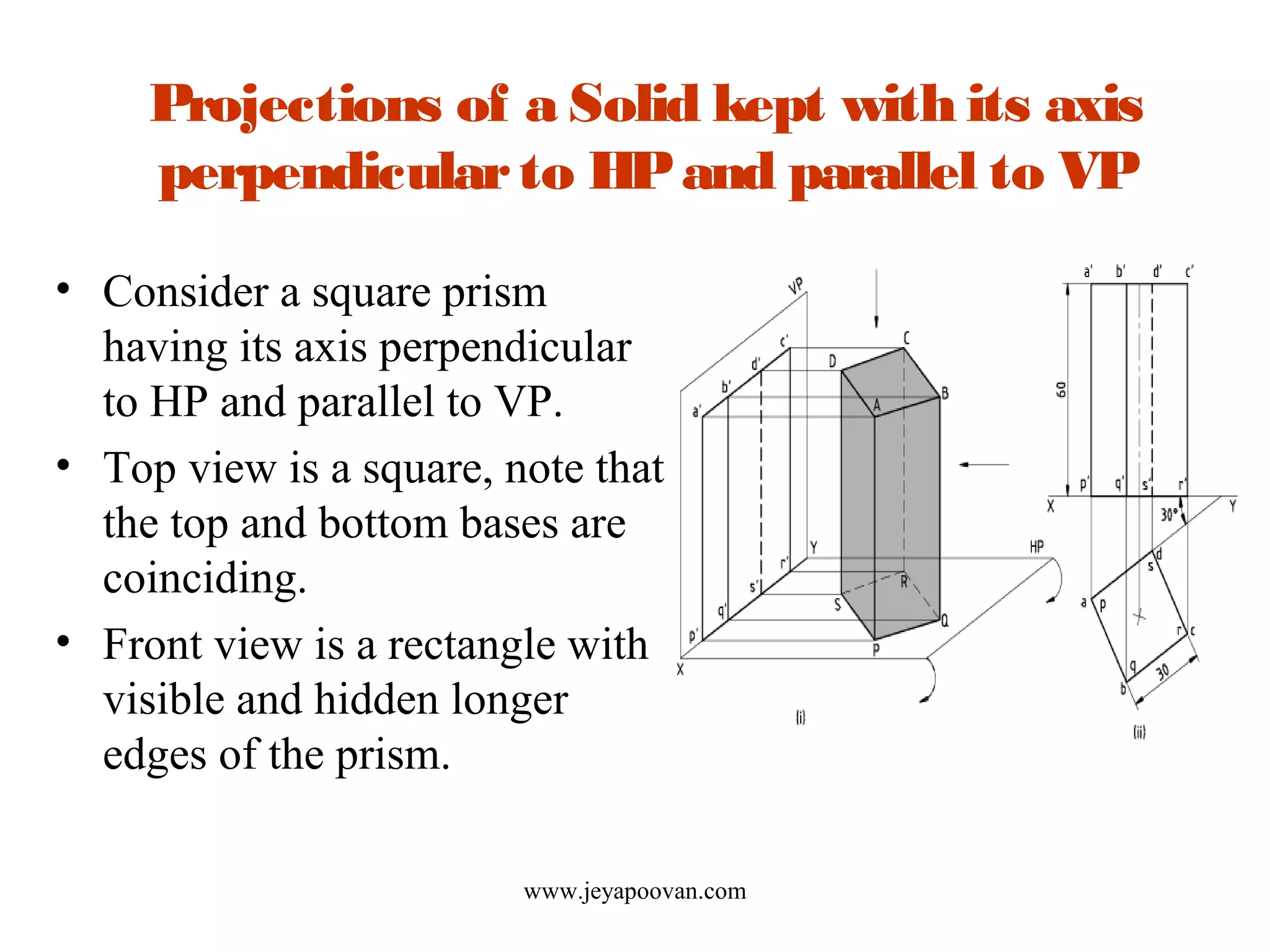
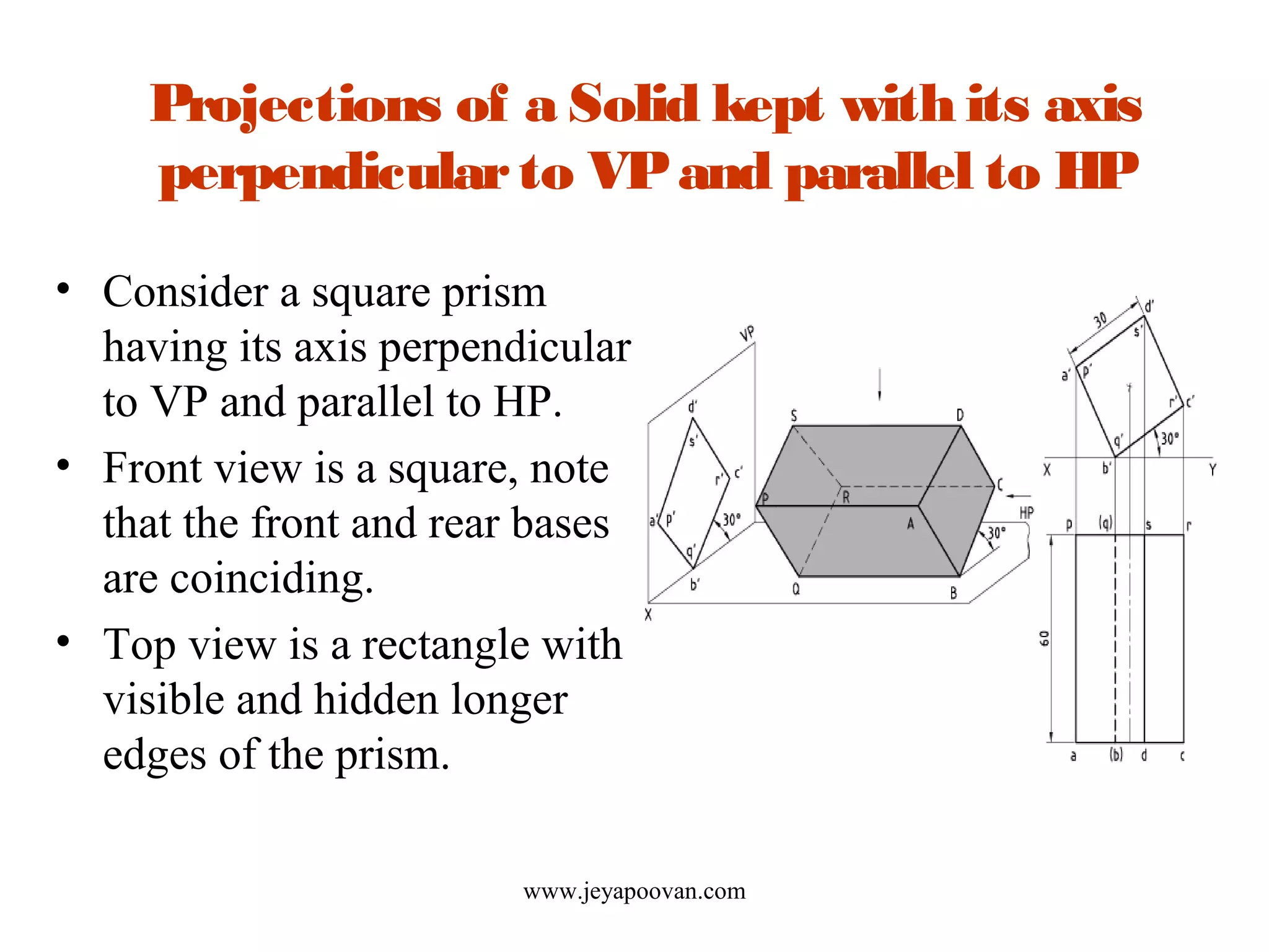
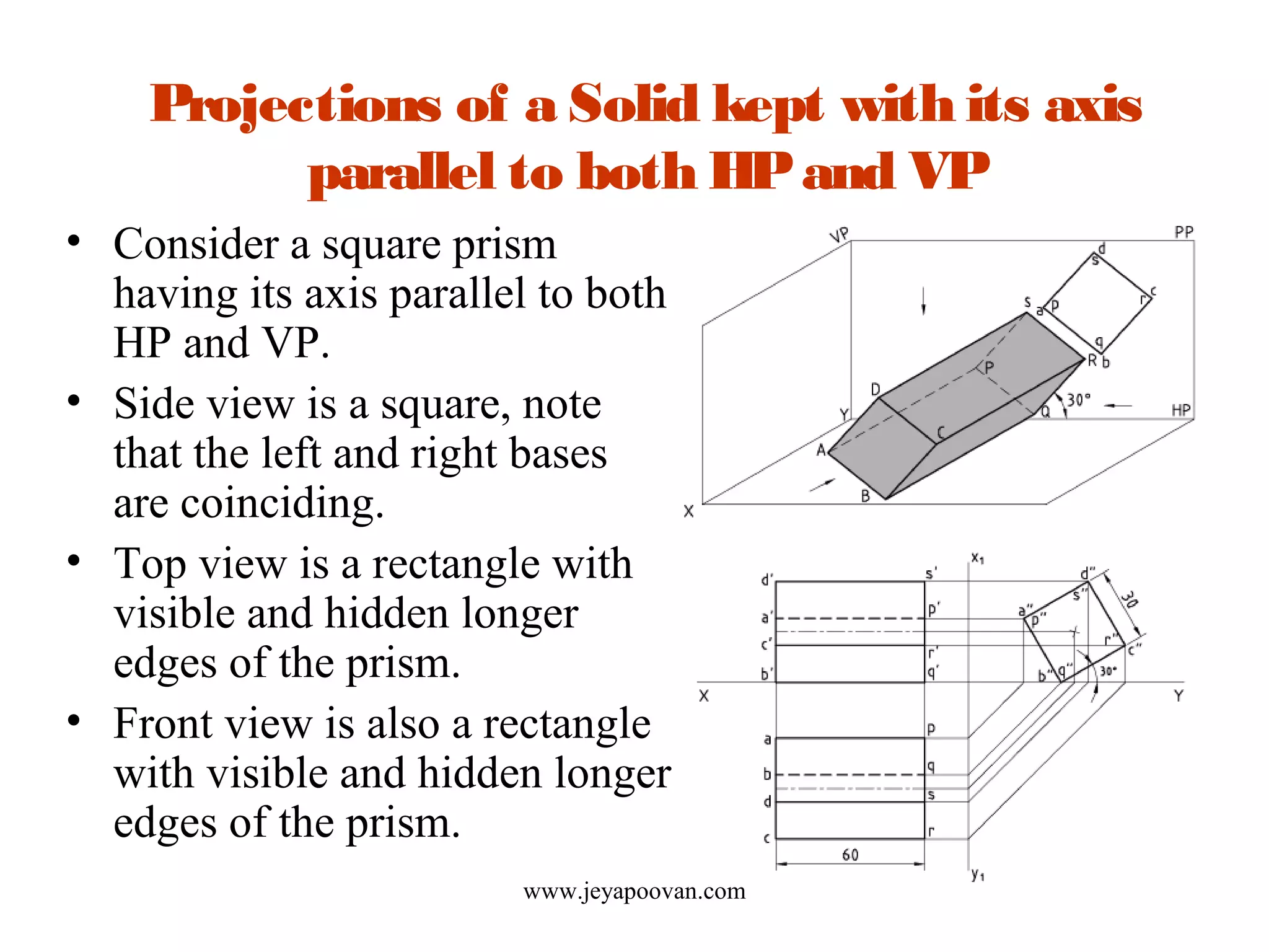
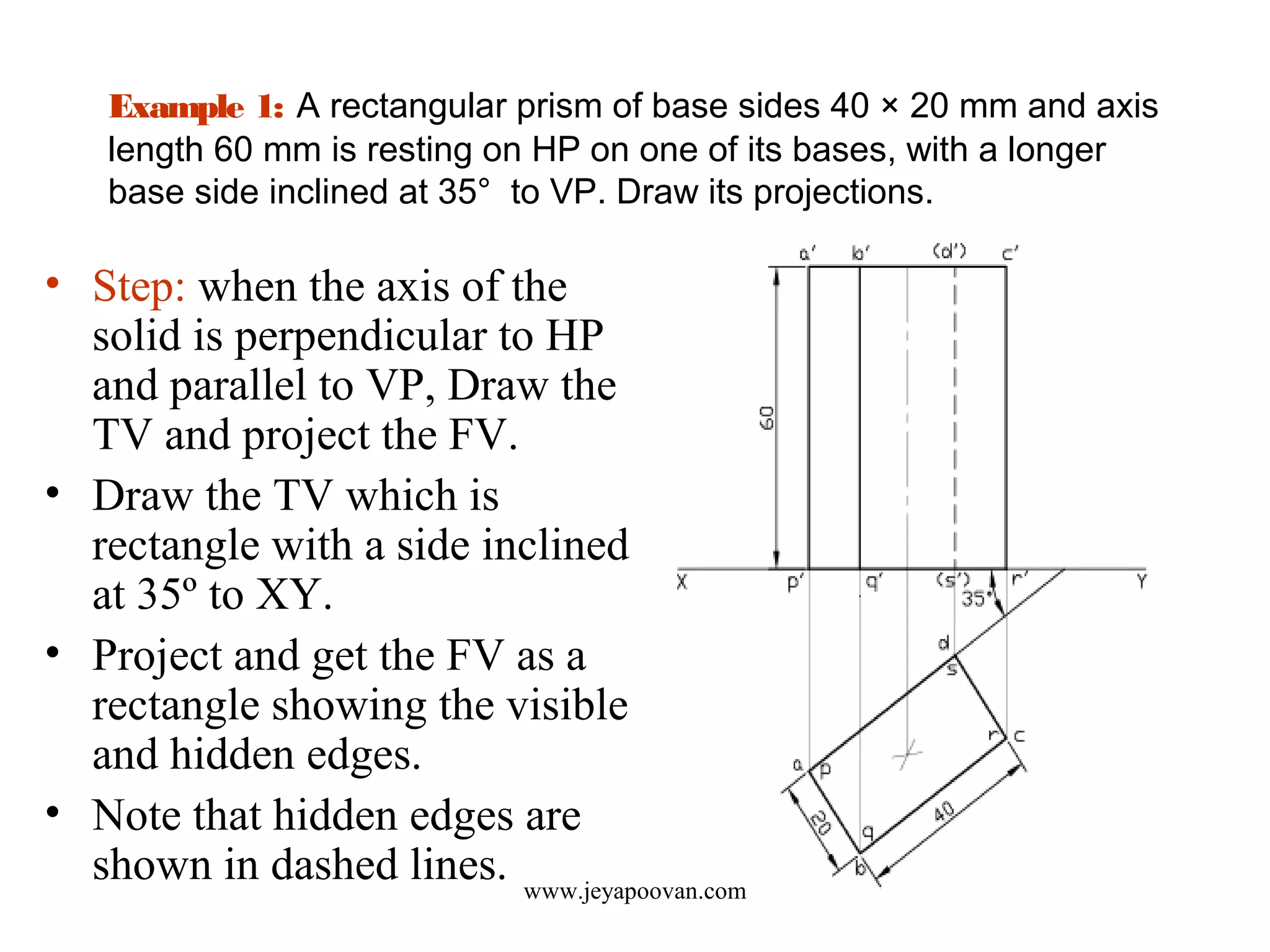
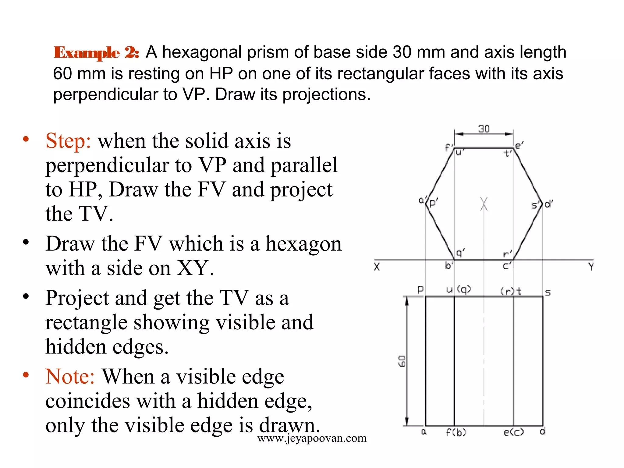
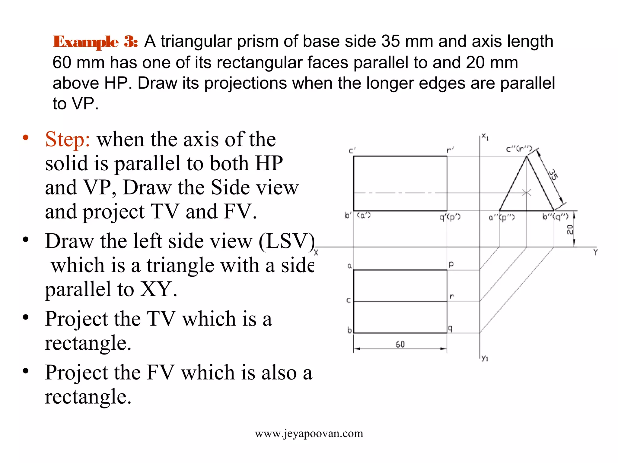
PROJECTIONS OF SOLIDS Part
I
Prof.T.JEYAPOOVAN
Department of Mechanical Engineering
Hindustan Institute of Technology and Science
Chennai-603103, India
www.jeyapoovan.com
SOLIDS
Tetrahedron Cube Octahedron
• A SOLID is a 3 dimensional object having length, breadth and
height. Commonly used solids are shown below.
www.jeyapoovan.com
SOLIDS
Square prism Rectangular prism
www.jeyapoovan.com
SOLIDS
Triangular Pentagonal Hexagonal
prism prism prism
www.jeyapoovan.com
SOLIDS
Square pyramid Rectangular pyramid
www.jeyapoovan.com
SOLIDS
Triangular Pentagonal Hexagonal
pyramid pyramid pyramid
www.jeyapoovan.com
SOLIDS
Cylinder Cone Sphere
www.jeyapoovan.com
Understanding
Projections of Solid
• Any one of the solids given above is kept in first
quadrant to draw its projections (TV, FV etc.).
• There are six different positions in which a solid
can be placed with reference to its axis and
reference planes (VP & HP).
• Your ability to visualize the solid and imagining
the correct position is necessary to understand
and draw the projections of the solid.
www.jeyapoovan.com
Projections of a Solid kept with its axis
perpendicularto HPand parallel to VP
• Consider a square prism
having its axis perpendicular
to HP and parallel to VP.
• Top view is a square, note that
the top and bottom bases are
coinciding.
• Front view is a rectangle with
visible and hidden longer
edges of the prism.
www.jeyapoovan.com
Projections of a Solid kept with its axis
perpendicularto VPand parallel to HP
• Consider a square prism
having its axis perpendicular
to VP and parallel to HP.
• Front view is a square, note
that the front and rear bases
are coinciding.
• Top view is a rectangle with
visible and hidden longer
edges of the prism.
www.jeyapoovan.com
Projections of a Solid kept with its axis
parallel to both HPand VP
• Consider a square prism
having its axis parallel to both
HP and VP.
• Side view is a square, note
that the left and right bases
are coinciding.
• Top view is a rectangle with
visible and hidden longer
edges of the prism.
• Front view is also a rectangle
with visible and hidden longer
edges of the prism.
www.jeyapoovan.com
Example 1: A rectangular prism of base sides 40 × 20 mm and axis
length 60 mm is resting on HP on one of its bases, with a longer
base side inclined at 35° to VP. Draw its projections.
• Step: when the axis of the
solid is perpendicular to HP
and parallel to VP, Draw the
TV and project the FV.
• Draw the TV which is
rectangle with a side inclined
at 35º to XY.
• Project and get the FV as a
rectangle showing the visible
and hidden edges.
• Note that hidden edges are
shown in dashed lines. www.jeyapoovan.com
Example 2: A hexagonal prism of base side 30 mm and axis length
60 mm is resting on HP on one of its rectangular faces with its axis
perpendicular to VP. Draw its projections.
• Step: when the solid axis is
perpendicular to VP and parallel
to HP, Draw the FV and project
the TV.
• Draw the FV which is a hexagon
with a side on XY.
• Project and get the TV as a
rectangle showing visible and
hidden edges.
• Note: When a visible edge
coincides with a hidden edge,
only the visible edge is drawn.www.jeyapoovan.com
Example 3: A triangular prism of base side 35 mm and axis length
60 mm has one of its rectangular faces parallel to and 20 mm
above HP. Draw its projections when the longer edges are parallel
to VP.
• Step: when the axis of the
solid is parallel to both HP
and VP, Draw the Side view
and project TV and FV.
• Draw the left side view (LSV)
which is a triangle with a side
parallel to XY.
• Project the TV which is a
rectangle.
• Project the FV which is also a
rectangle.
www.jeyapoovan.com
Tips to draw visible and hidden edges
• Read the given problem carefully and understand the FV
and TV in that position and follow the steps as given
against each position.
• Draw one of the views and project the other view.
• All boundary edges in any view are always visible.
• Edges in upper half of a solid, i.e. above axis in front
view, is always visible in top view. Other edges are
drawn in dashed lines.
• Edges in front half of a solid, i.e. in front of axis in top
view, is always visible in front view. Other edges are
drawn in dashed lines.
www.jeyapoovan.com
www.jeyapoovan.com
REFERENCE BOOKS
1. Jeyapoovan T, “Lesson Plans for Engineering
Graphics”, 2010, Vikas Publishing House Pvt
Ltd, New Delhi.
2. Jeyapoovan T, “Engineering Drawing and
Graphics”, 2011, Vikas Publishing House Pvt
Ltd, New Delhi.
End of Lesson 4
ThankYou
www.jeyapoovan.com

Lesson 4 Projections of Solids - Part I

  • 1.
    PROJECTIONS OF SOLIDSPart I Prof.T.JEYAPOOVAN Department of Mechanical Engineering Hindustan Institute of Technology and Science Chennai-603103, India www.jeyapoovan.com
  • 2.
    SOLIDS Tetrahedron Cube Octahedron •A SOLID is a 3 dimensional object having length, breadth and height. Commonly used solids are shown below. www.jeyapoovan.com
  • 3.
    SOLIDS Square prism Rectangularprism www.jeyapoovan.com
  • 4.
    SOLIDS Triangular Pentagonal Hexagonal prismprism prism www.jeyapoovan.com
  • 5.
    SOLIDS Square pyramid Rectangularpyramid www.jeyapoovan.com
  • 6.
    SOLIDS Triangular Pentagonal Hexagonal pyramidpyramid pyramid www.jeyapoovan.com
  • 7.
  • 8.
    Understanding Projections of Solid •Any one of the solids given above is kept in first quadrant to draw its projections (TV, FV etc.). • There are six different positions in which a solid can be placed with reference to its axis and reference planes (VP & HP). • Your ability to visualize the solid and imagining the correct position is necessary to understand and draw the projections of the solid. www.jeyapoovan.com
  • 9.
    Projections of aSolid kept with its axis perpendicularto HPand parallel to VP • Consider a square prism having its axis perpendicular to HP and parallel to VP. • Top view is a square, note that the top and bottom bases are coinciding. • Front view is a rectangle with visible and hidden longer edges of the prism. www.jeyapoovan.com
  • 10.
    Projections of aSolid kept with its axis perpendicularto VPand parallel to HP • Consider a square prism having its axis perpendicular to VP and parallel to HP. • Front view is a square, note that the front and rear bases are coinciding. • Top view is a rectangle with visible and hidden longer edges of the prism. www.jeyapoovan.com
  • 11.
    Projections of aSolid kept with its axis parallel to both HPand VP • Consider a square prism having its axis parallel to both HP and VP. • Side view is a square, note that the left and right bases are coinciding. • Top view is a rectangle with visible and hidden longer edges of the prism. • Front view is also a rectangle with visible and hidden longer edges of the prism. www.jeyapoovan.com
  • 12.
    Example 1: Arectangular prism of base sides 40 × 20 mm and axis length 60 mm is resting on HP on one of its bases, with a longer base side inclined at 35° to VP. Draw its projections. • Step: when the axis of the solid is perpendicular to HP and parallel to VP, Draw the TV and project the FV. • Draw the TV which is rectangle with a side inclined at 35º to XY. • Project and get the FV as a rectangle showing the visible and hidden edges. • Note that hidden edges are shown in dashed lines. www.jeyapoovan.com
  • 13.
    Example 2: Ahexagonal prism of base side 30 mm and axis length 60 mm is resting on HP on one of its rectangular faces with its axis perpendicular to VP. Draw its projections. • Step: when the solid axis is perpendicular to VP and parallel to HP, Draw the FV and project the TV. • Draw the FV which is a hexagon with a side on XY. • Project and get the TV as a rectangle showing visible and hidden edges. • Note: When a visible edge coincides with a hidden edge, only the visible edge is drawn.www.jeyapoovan.com
  • 14.
    Example 3: Atriangular prism of base side 35 mm and axis length 60 mm has one of its rectangular faces parallel to and 20 mm above HP. Draw its projections when the longer edges are parallel to VP. • Step: when the axis of the solid is parallel to both HP and VP, Draw the Side view and project TV and FV. • Draw the left side view (LSV) which is a triangle with a side parallel to XY. • Project the TV which is a rectangle. • Project the FV which is also a rectangle. www.jeyapoovan.com
  • 15.
    Tips to drawvisible and hidden edges • Read the given problem carefully and understand the FV and TV in that position and follow the steps as given against each position. • Draw one of the views and project the other view. • All boundary edges in any view are always visible. • Edges in upper half of a solid, i.e. above axis in front view, is always visible in top view. Other edges are drawn in dashed lines. • Edges in front half of a solid, i.e. in front of axis in top view, is always visible in front view. Other edges are drawn in dashed lines. www.jeyapoovan.com
  • 16.
    www.jeyapoovan.com REFERENCE BOOKS 1. JeyapoovanT, “Lesson Plans for Engineering Graphics”, 2010, Vikas Publishing House Pvt Ltd, New Delhi. 2. Jeyapoovan T, “Engineering Drawing and Graphics”, 2011, Vikas Publishing House Pvt Ltd, New Delhi.
  • 17.
    End of Lesson4 ThankYou www.jeyapoovan.com