Download as PDF, PPTX


UML (Unified Modeling Language) is a standard language for modeling software systems using graphical diagrams. There are several types of UML diagrams that can be used at different stages of development, including structural diagrams like class and component diagrams, behavioral diagrams like activity and state machine diagrams, and interaction diagrams like sequence and communication diagrams. The document provides examples and descriptions of many common UML diagram types like class, component, deployment, activity, and sequence diagrams and discusses how each can be used to model different aspects of a software system.
Introduction to the lecture on UML diagrams by Mr. Mubashir Ali, covering its role in software engineering.
Definition of UML as a standard language for documenting software systems, promoting better communication and architectural design.
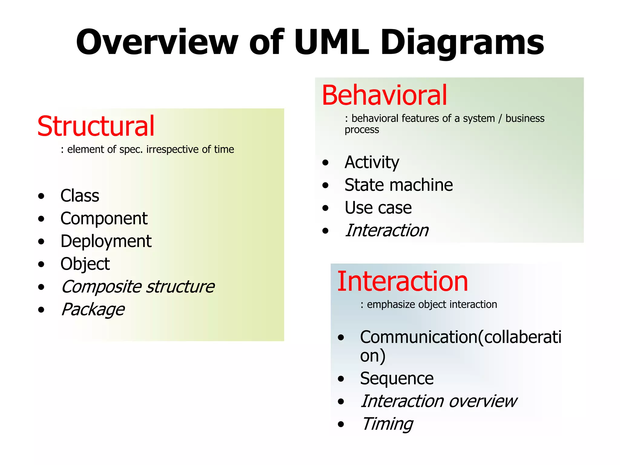
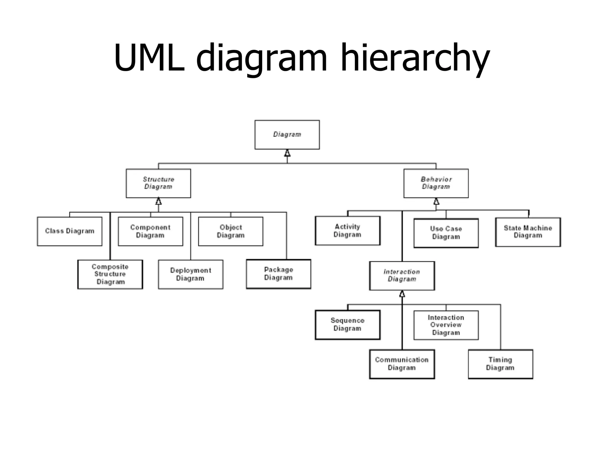
Overview of UML diagram types: Structural, Behavioral, and Interaction diagrams, each serving distinct modeling purposes.
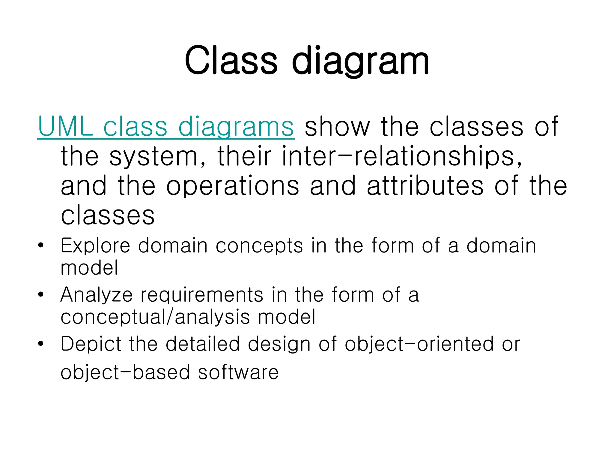
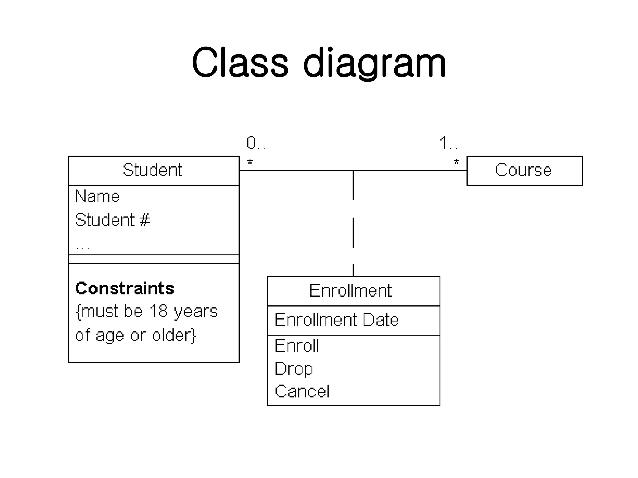
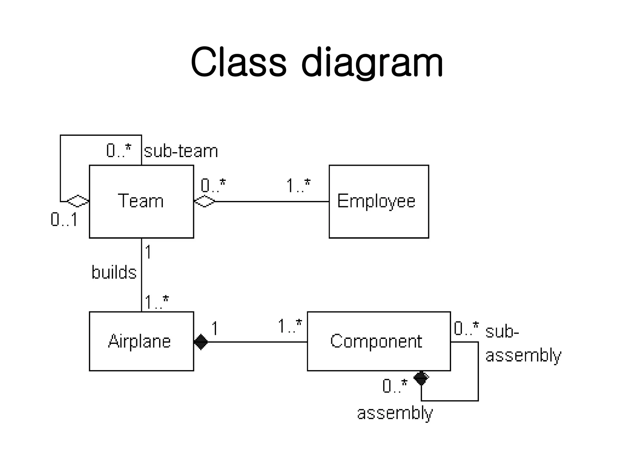
Class diagrams depict classes, their relationships, attributes, and operations, critical for domain modeling.
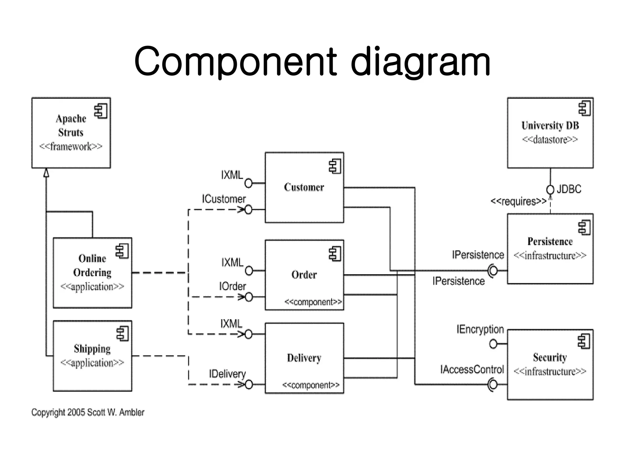
Component diagrams illustrate dependencies among software components, detailing their relationships and implementations.
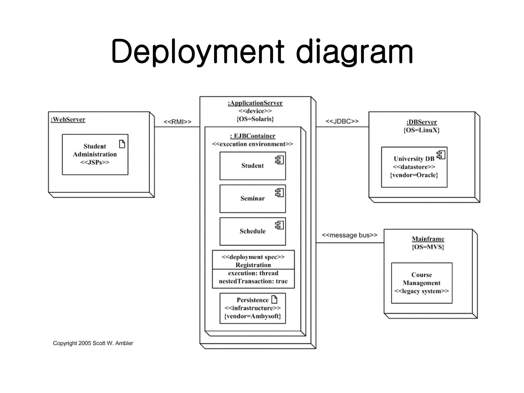
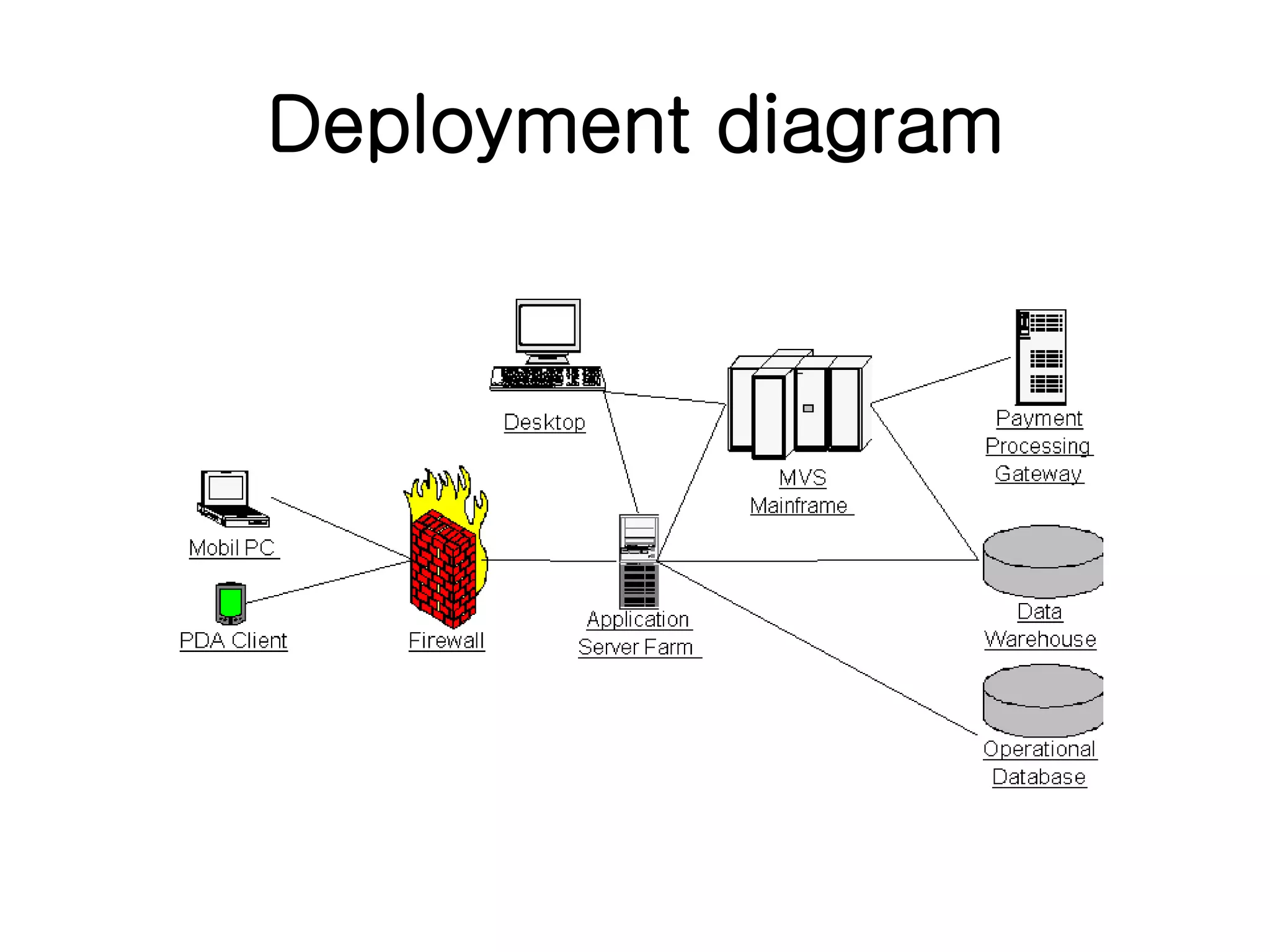
Deployment diagrams provide a static view of the runtime configuration, including hardware nodes and software components.
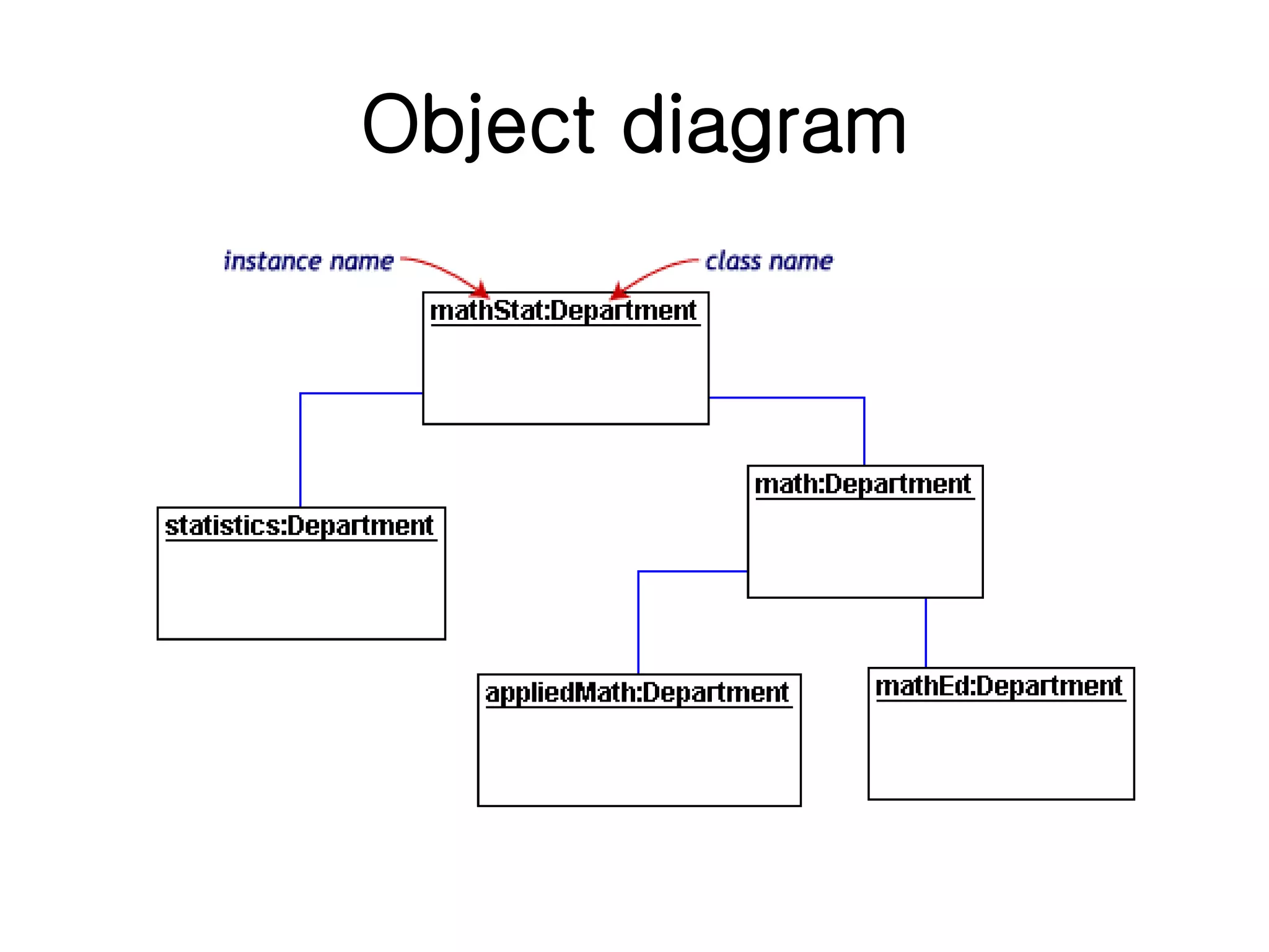
Object diagrams focus on real-world object instances and their relationships, aiding in the explanation of complex systems.
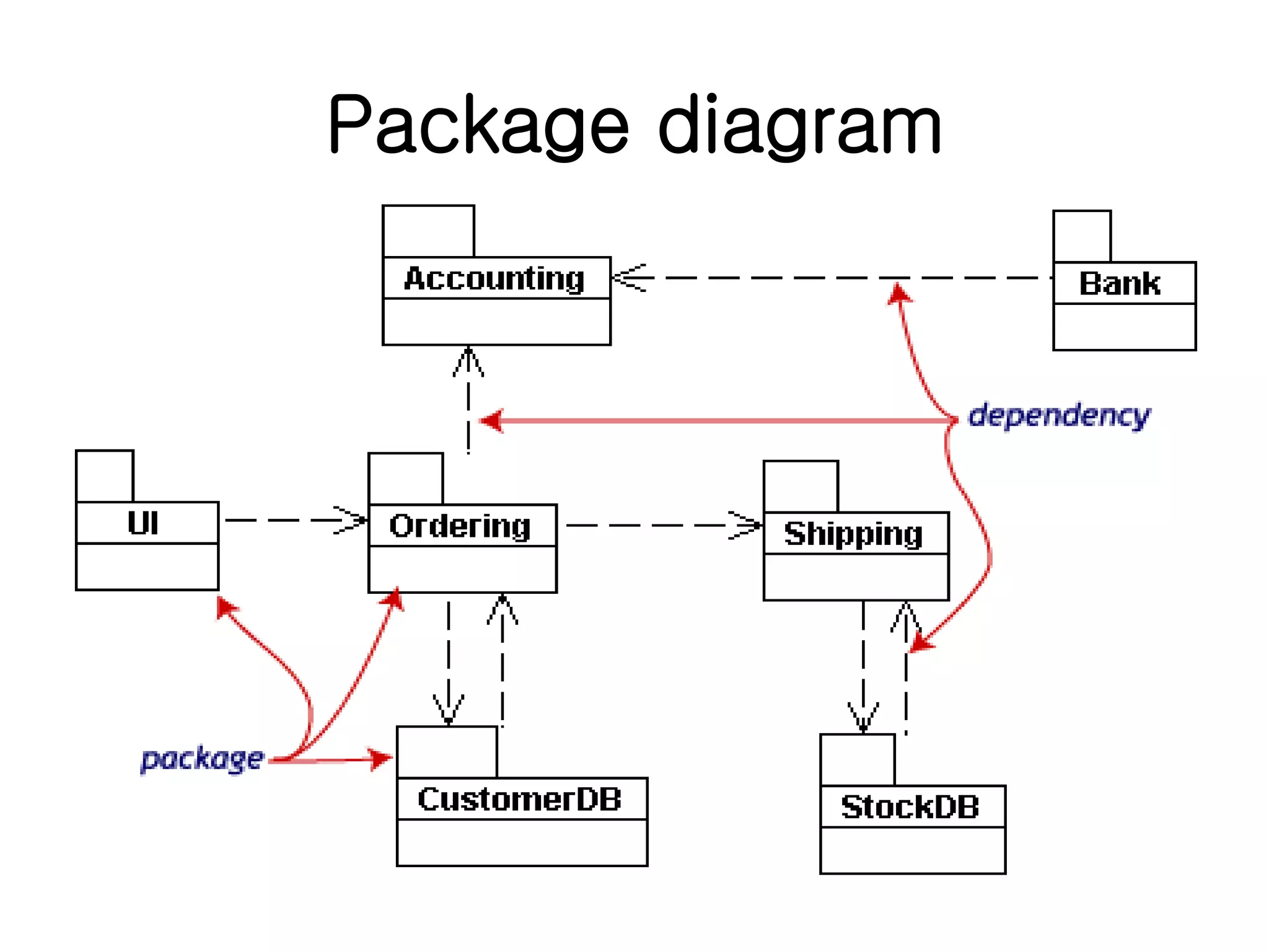
Package diagrams group classes into packages to simplify complex diagrams, represented as file folders.
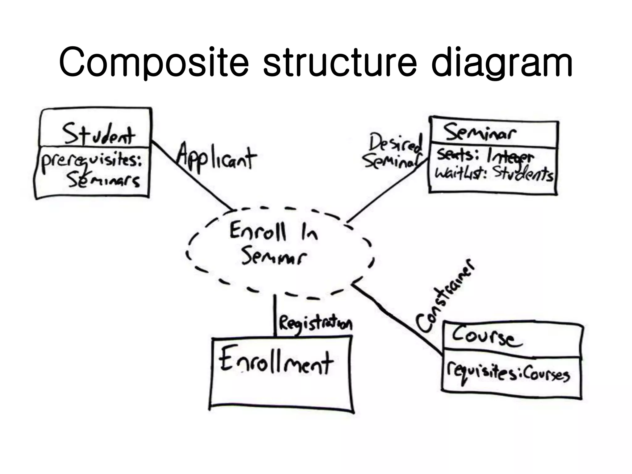
Composite structure diagrams explore collaborative instances and their internal structure, detailing parts and connectors.
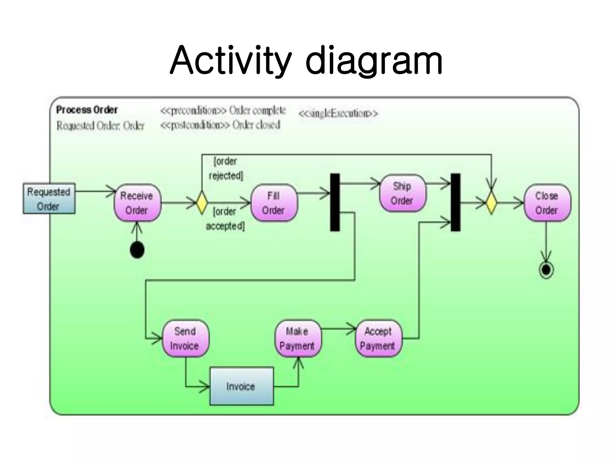
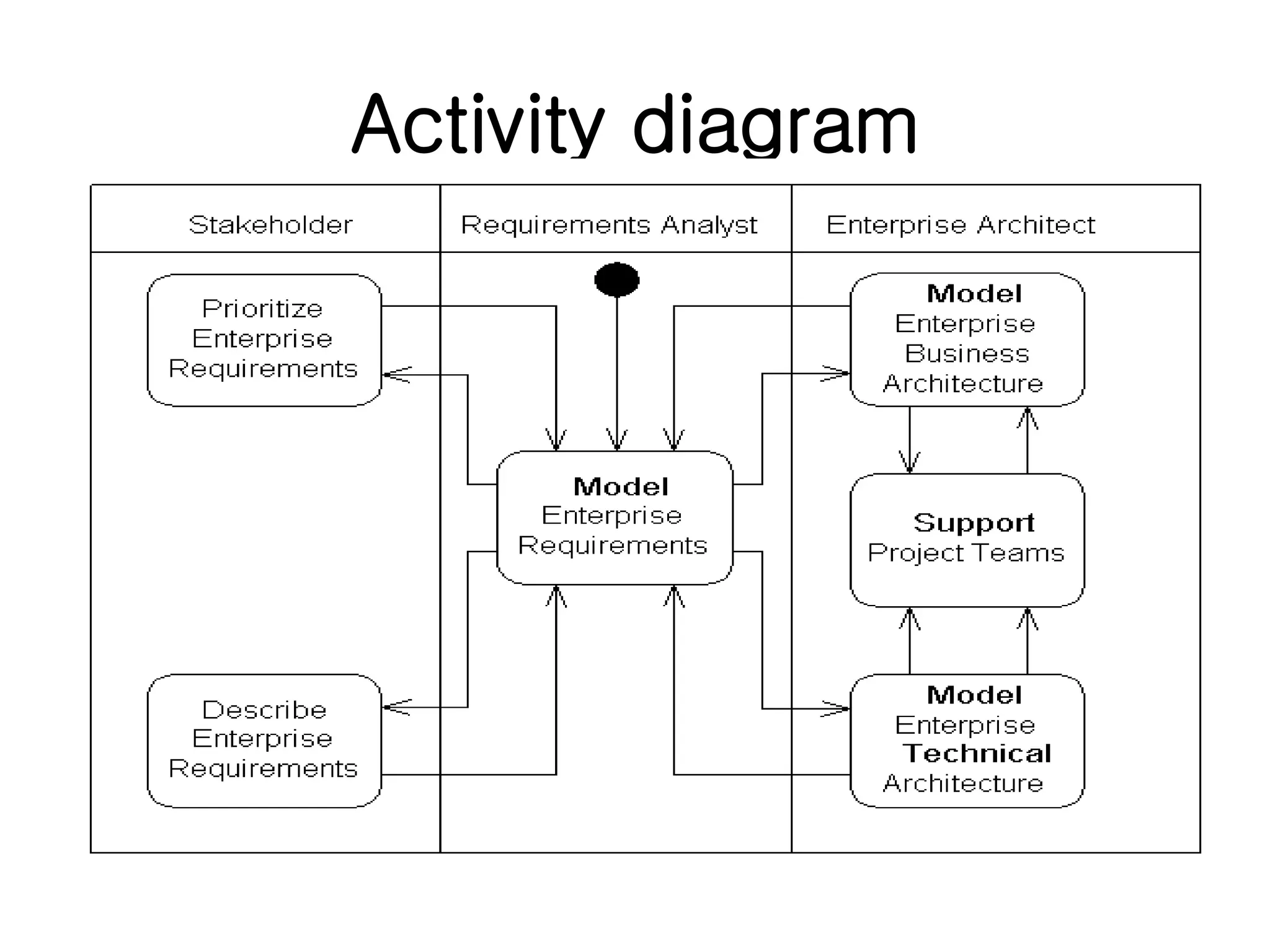
Activity diagrams illustrate the flow of control in systems, equivalent to flow charts and describing business processes.
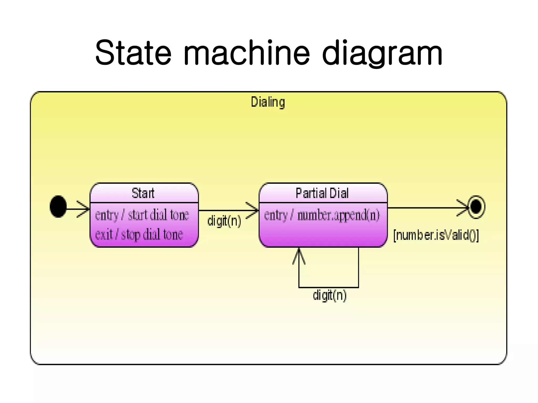
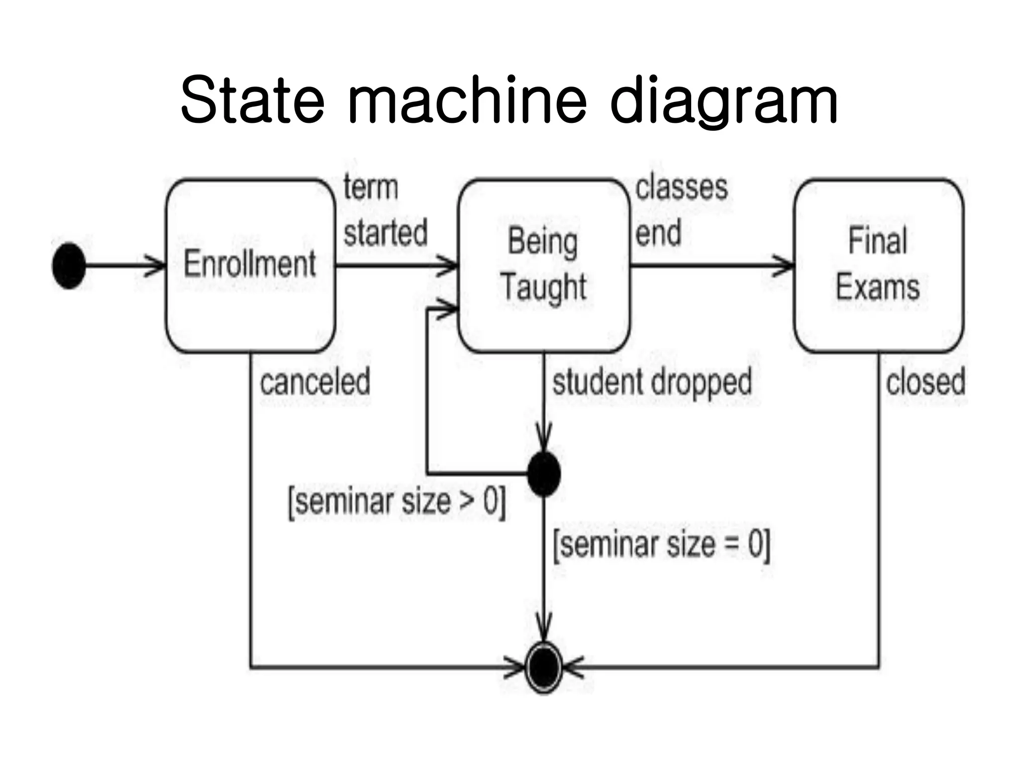
State machine diagrams depict the states of an entity and responses to events, effectively modeling its behavior.
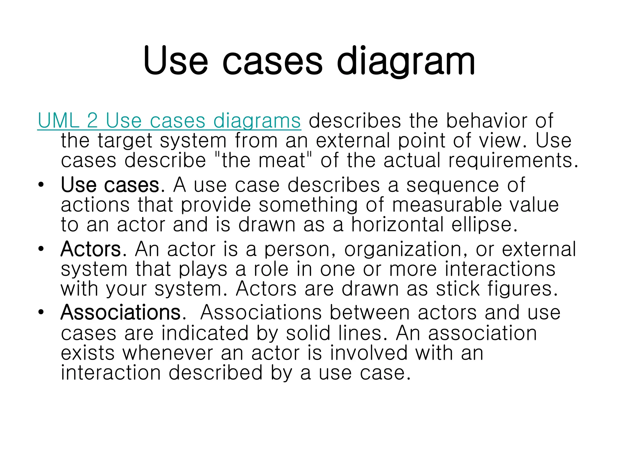
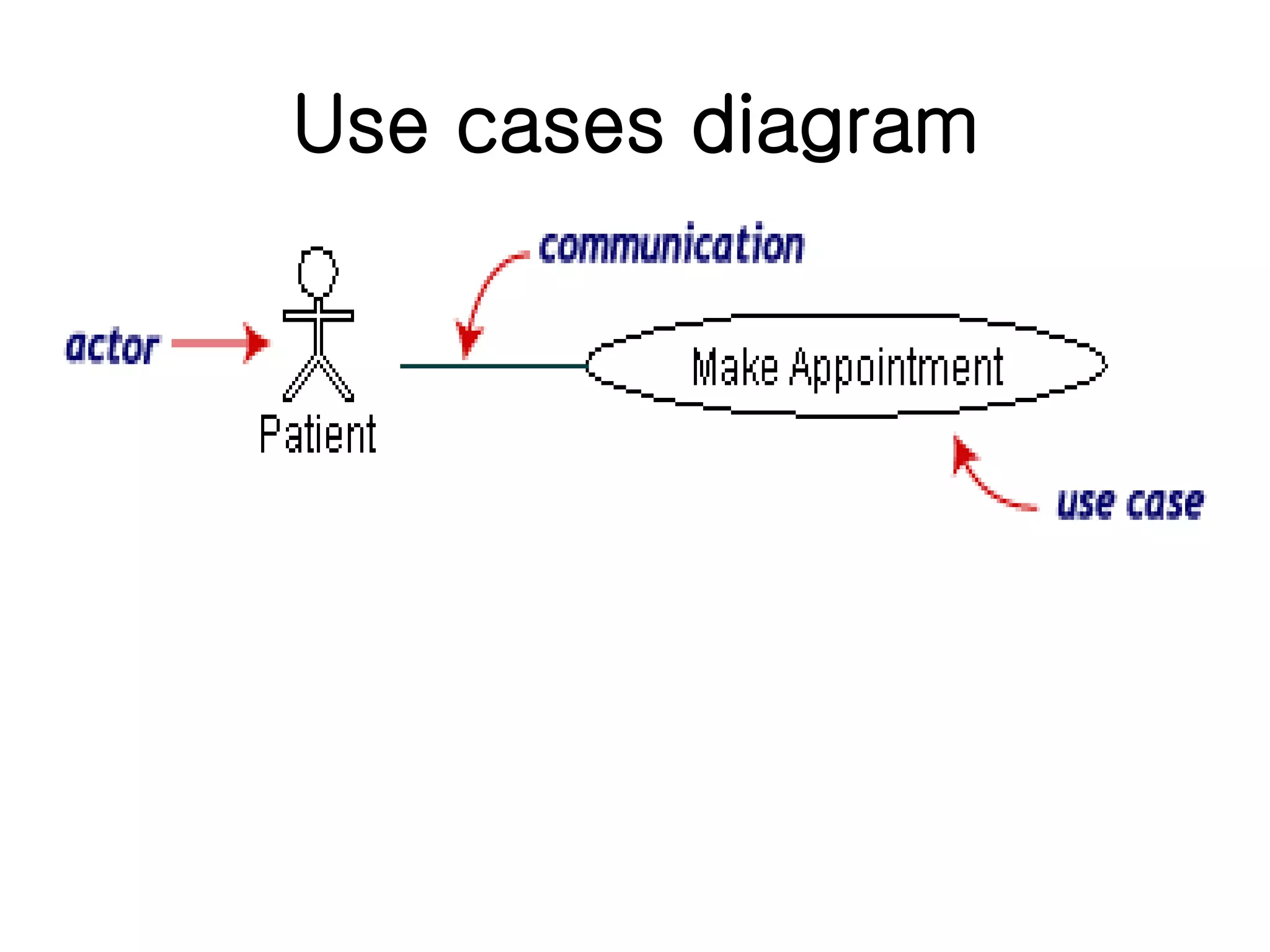
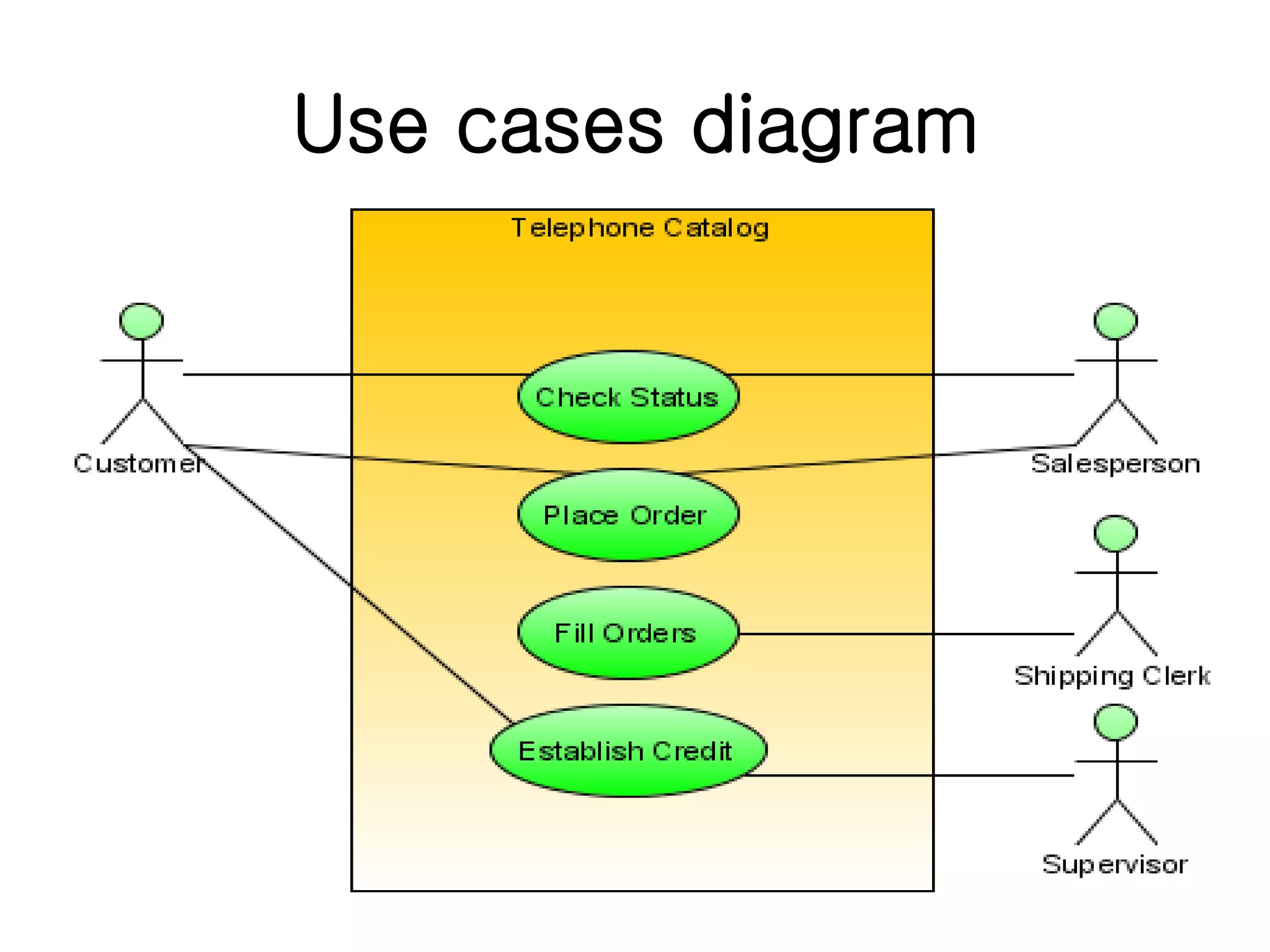
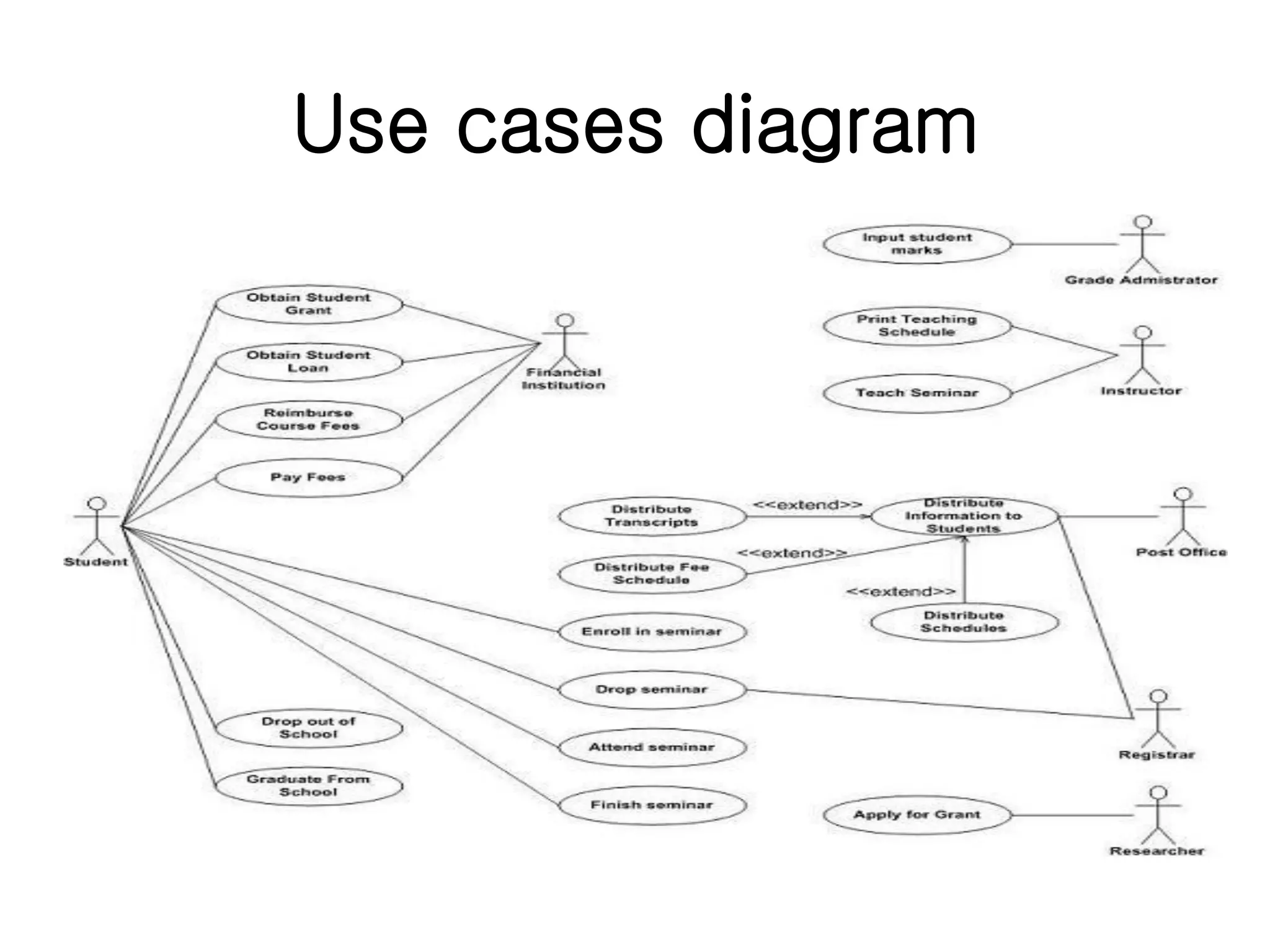
Use case diagrams outline system behaviors from an external viewpoint, detailing interactions between actors and use cases.
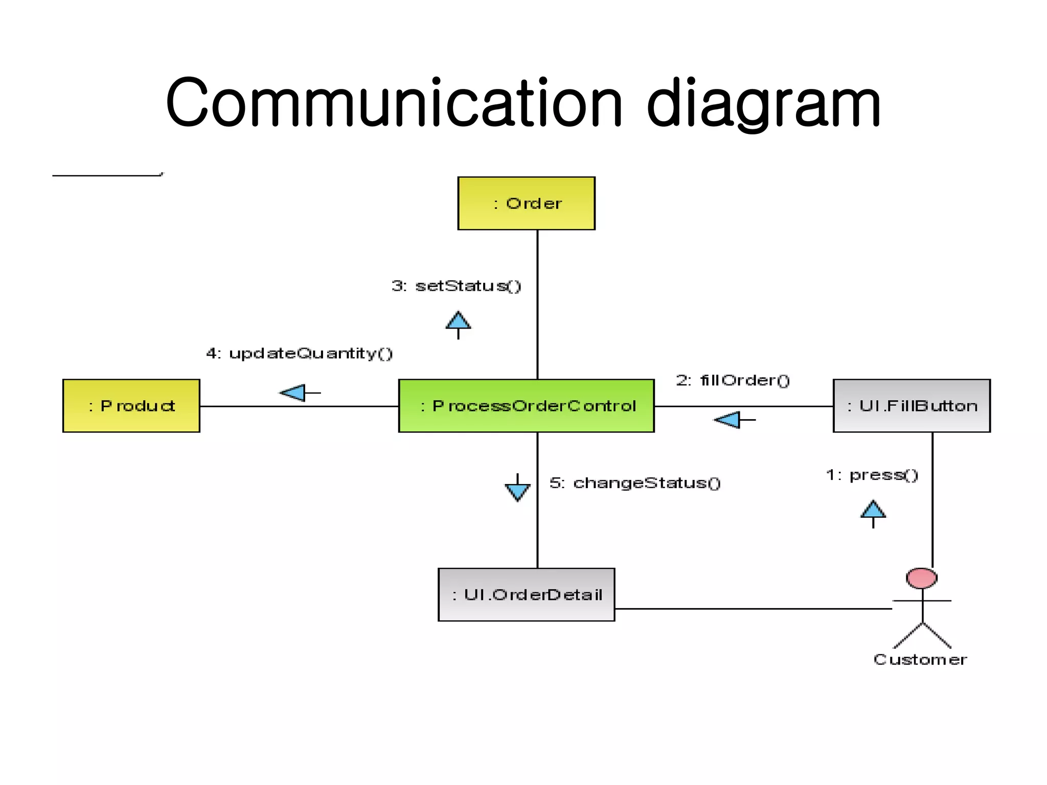
Communication diagrams model dynamic behavior and focus on the collaboration among objects in use cases.
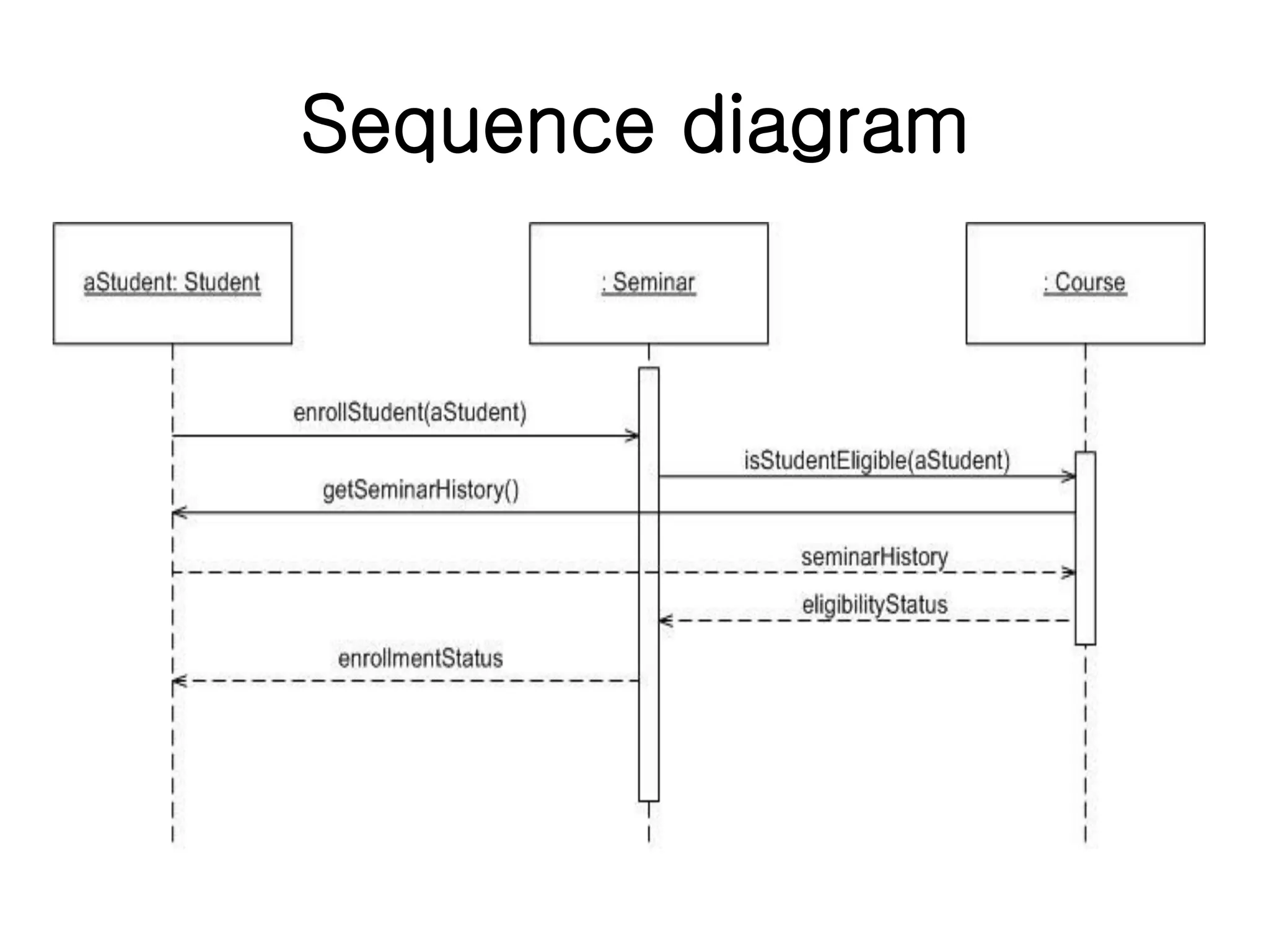
Sequence diagrams showcase object interactions over time, illustrating collaborations within specific use case scenarios.
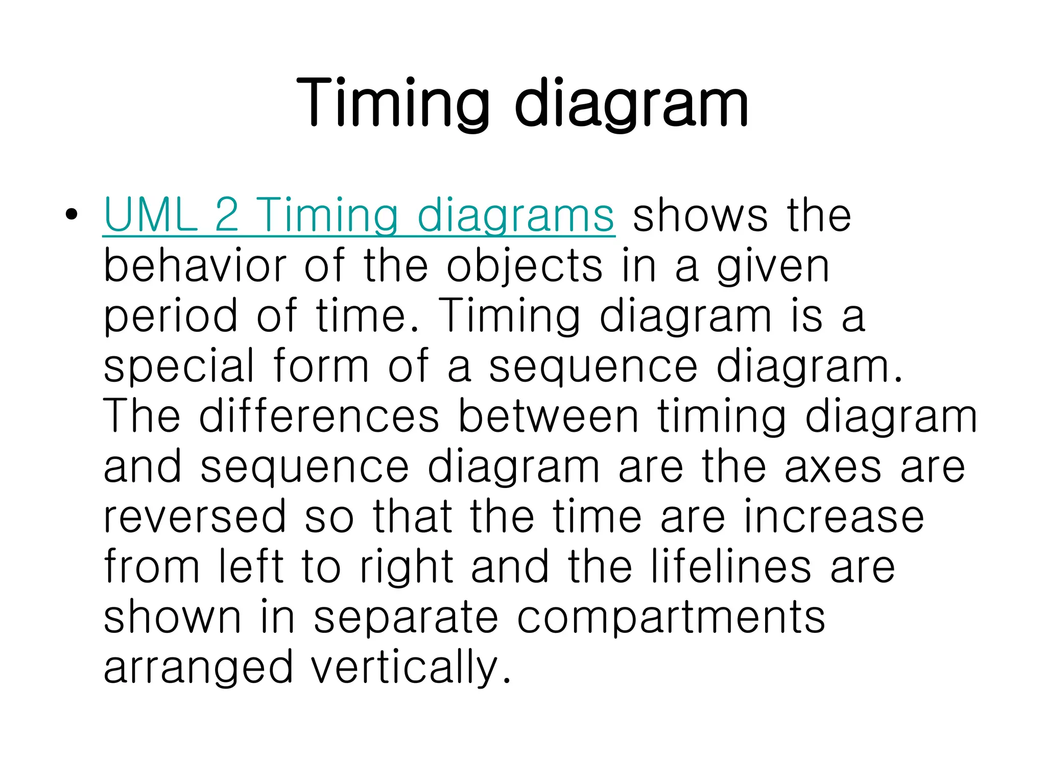
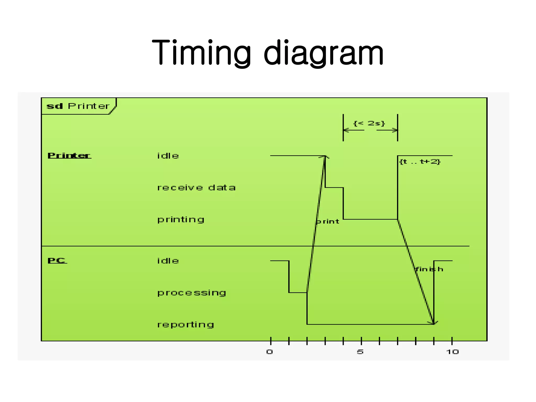
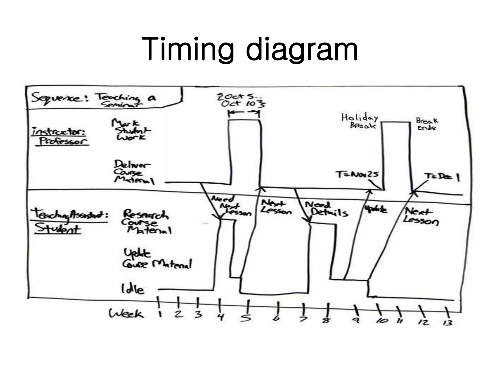
Timing diagrams present object behaviors across time periods, highlighting distinctions from sequence diagrams.
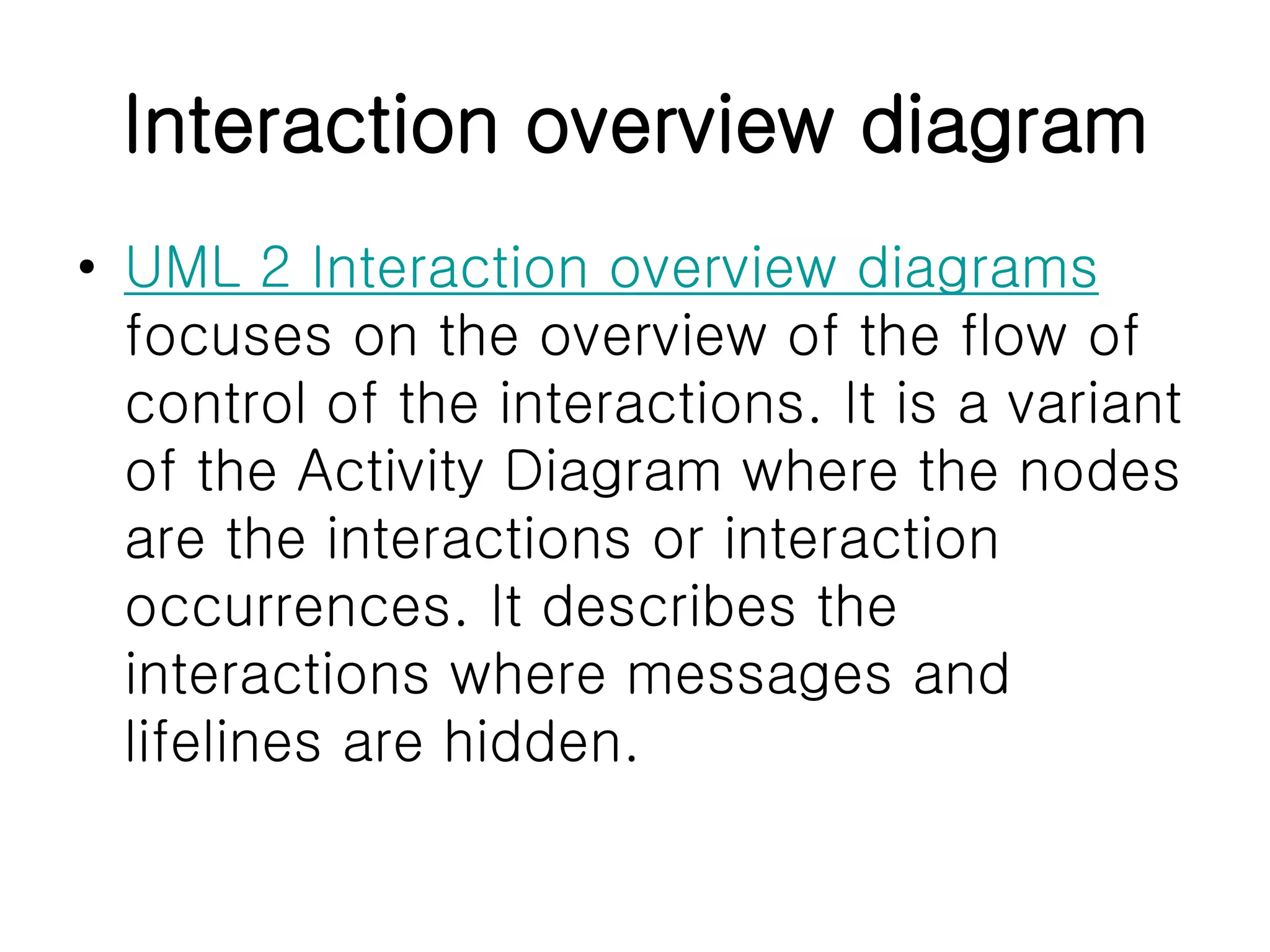
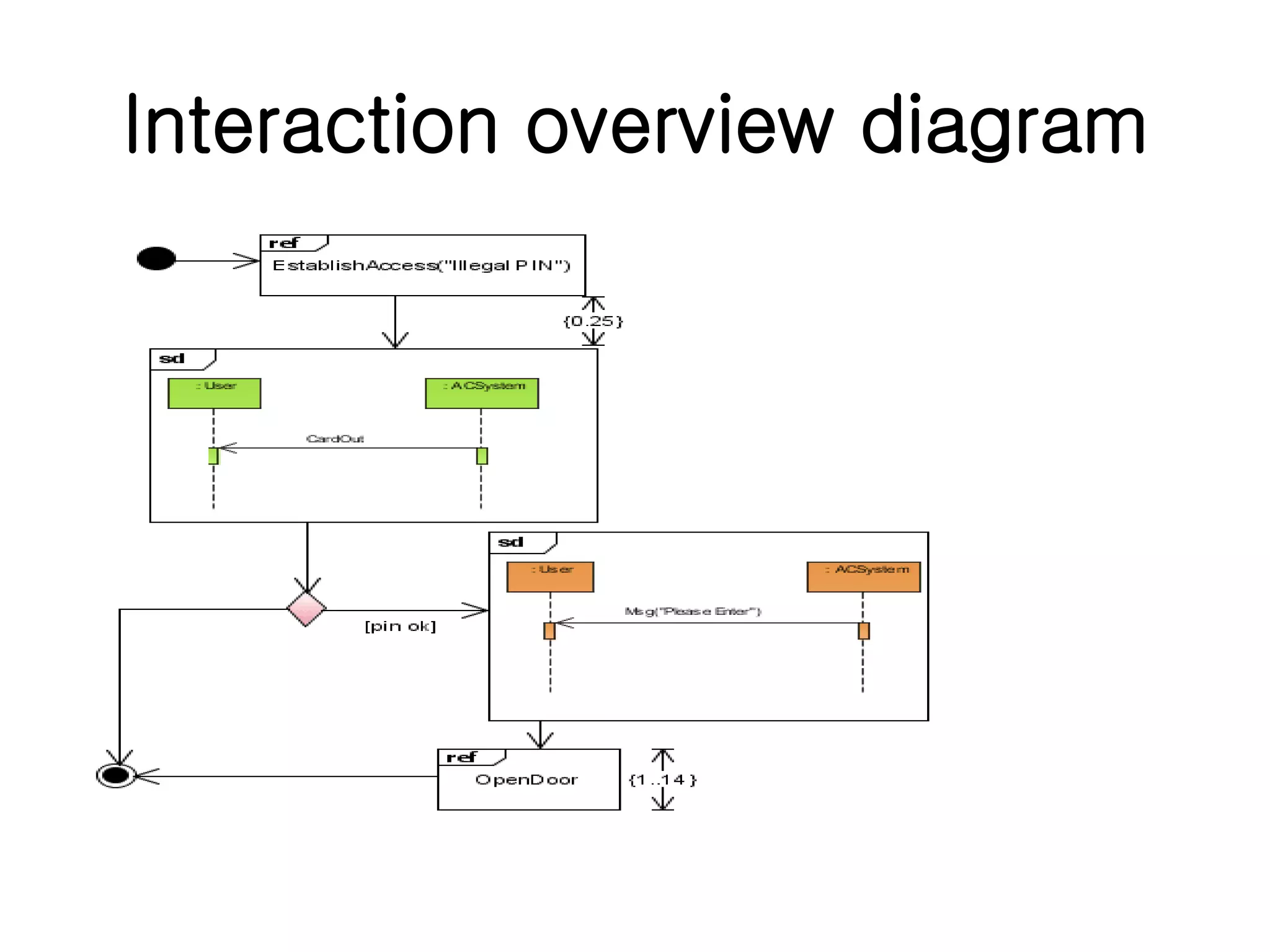
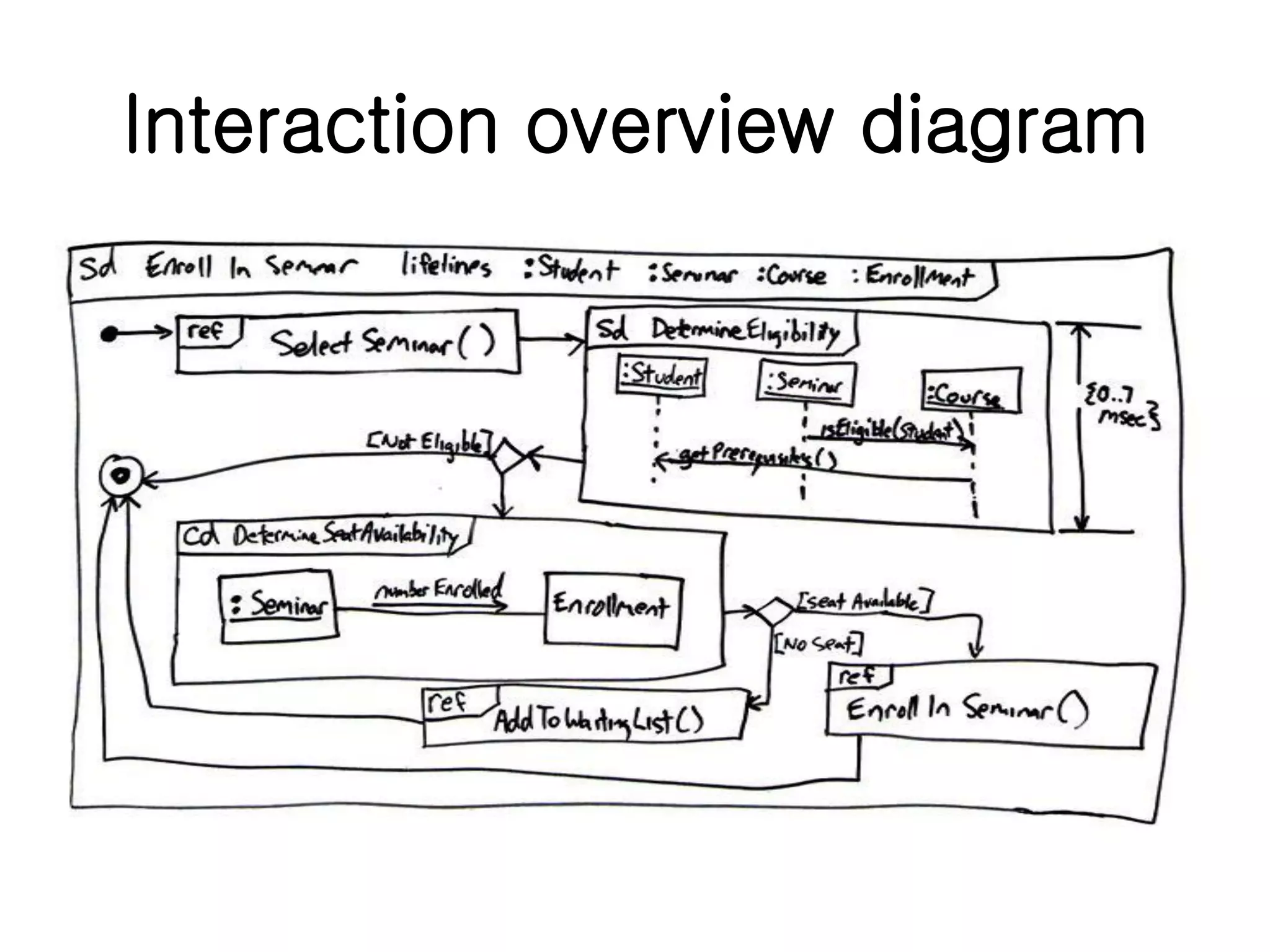
Interaction overview diagrams provide a high-level view of interaction control flows, emphasizing node connections.
Summary of the UML diagram hierarchy, visually organizing diagrams into categories based on their features.
References for further reading and resources concerning UML and related modeling techniques.