A Brief History
FromCarriages to Cars
The laminated spring, also called a leaf spring, was invented in the
early 1800s by Obadiah Elliott for horse carriages.
His design was revolutionary for horse-drawn carriages,
providing a much smoother, more durable ride. This basic,
effective design transitioned directly into the first automobiles.
4.
Commonly Known As...
Alaminated spring is more commonly known as a
leaf spring. It is one of the oldest and most widely-
used forms of suspension for wheeled vehicles.
Simple Construction
It consists of one or more arc-shaped strips of spring
steel, called 'leaves' or 'laminations', stacked together
to absorb shock and support a vehicle's weight.
What is a Laminated Spring?
5.
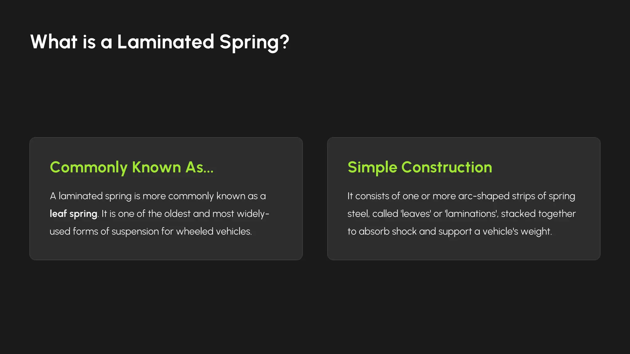
How They Work
Laminatedsprings work on the principle of bending
resistance. When a wheel hits a bump, the axle moves up,
causing the arched spring to flatten. The spring's elasticity
resists this, absorbing the impact and returning to its original
shape.
The Core Principle
6.
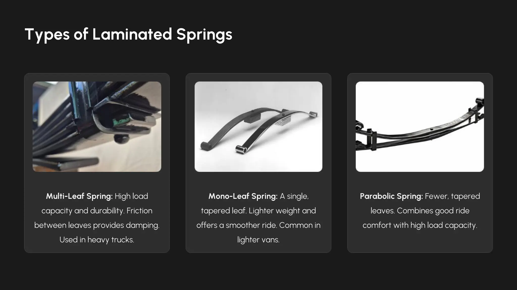
Multi-Leaf Spring: Highload
capacity and durability. Friction
between leaves provides damping.
Used in heavy trucks.
Mono-Leaf Spring: A single,
tapered leaf. Lighter weight and
offers a smoother ride. Common in
lighter vans.
Parabolic Spring: Fewer, tapered
leaves. Combines good ride
comfort with high load capacity.
Types of Laminated Springs
7.
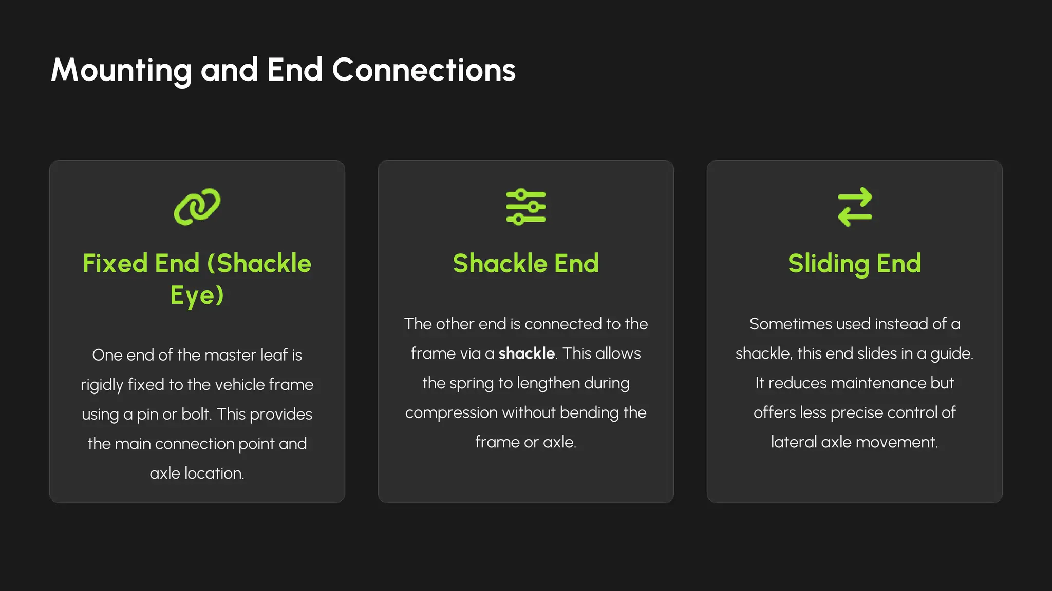
Fixed End (Shackle
Eye)
Oneend of the master leaf is
rigidly fixed to the vehicle frame
using a pin or bolt. This provides
the main connection point and
axle location.
Shackle End
The other end is connected to the
frame via a shackle. This allows
the spring to lengthen during
compression without bending the
frame or axle.
Sliding End
Sometimes used instead of a
shackle, this end slides in a guide.
It reduces maintenance but
offers less precise control of
lateral axle movement.
Mounting and End Connections
8.
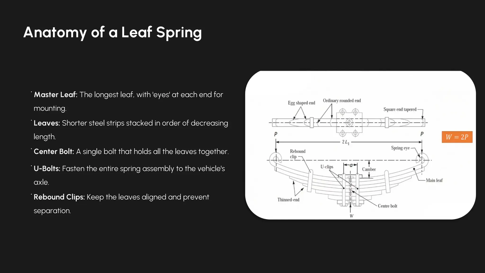
• Master Leaf:The longest leaf, with 'eyes' at each end for
mounting.
• Leaves: Shorter steel strips stacked in order of decreasing
length.
• Center Bolt: A single bolt that holds all the leaves together.
• U-Bolts: Fasten the entire spring assembly to the vehicle's
axle.
• Rebound Clips: Keep the leaves aligned and prevent
separation.
Anatomy of a Leaf Spring
9.
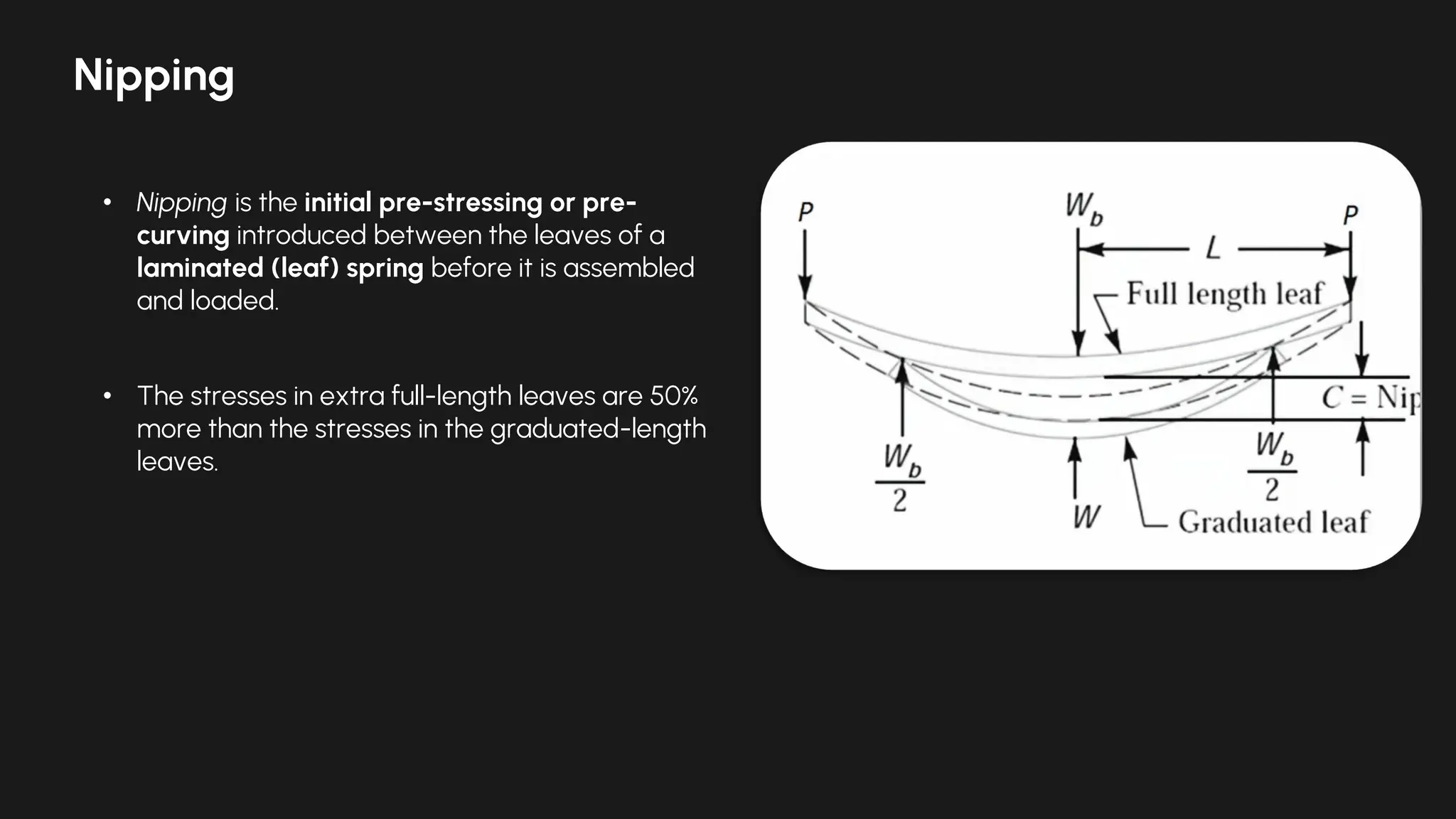
Nipping
• Nipping isthe initial pre-stressing or pre-
curving introduced between the leaves of a
laminated (leaf) spring before it is assembled
and loaded.
• The stresses in extra full-length leaves are 50%
more than the stresses in the graduated-length
leaves.
10.
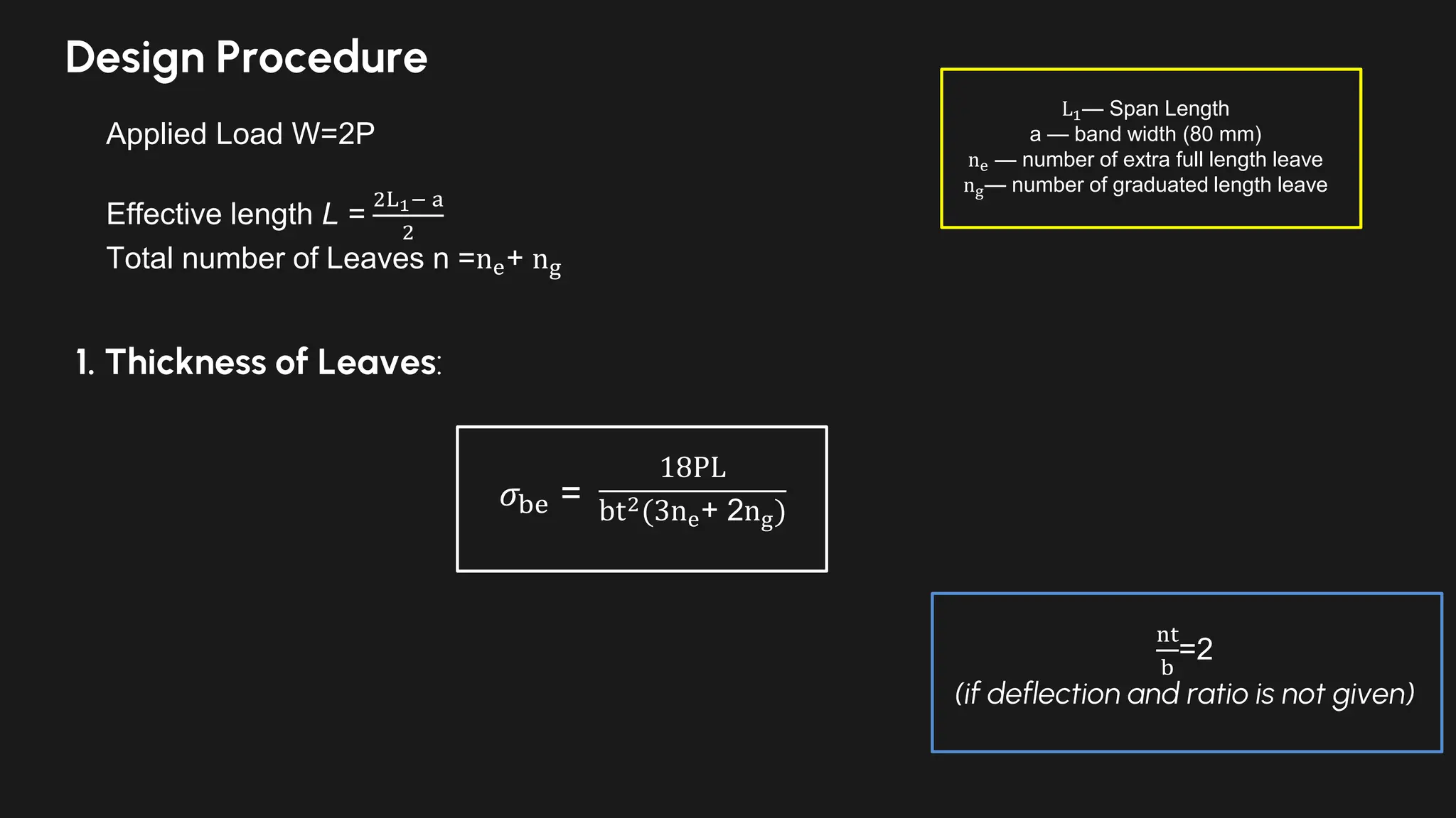
Design Procedure
Applied LoadW=2P
Effective length L =
2L1− a
2
Total number of Leaves n =ne+ ng
L1— Span Length
a — band width (80 mm)
ne — number of extra full length leave
ng— number of graduated length leave
1. Thickness of Leaves:
18PL
bt2(3ne+ 2ng)
𝜎be =
nt
b
=2
(if deflection and ratio is not given)
High Load Capacity:Excellent at supporting very heavy loads, ideal for commercial vehicles.
Durability & Simplicity: Robust design with few moving parts; inherently simple to repair or
replace.
Cost-Effective: Simple to manufacture and requires less complex metallurgy than other
suspension components.
Axle Location: The spring itself locates and controls the motion of the axle, often eliminating the
need for trailing arms.
Advantages
15.
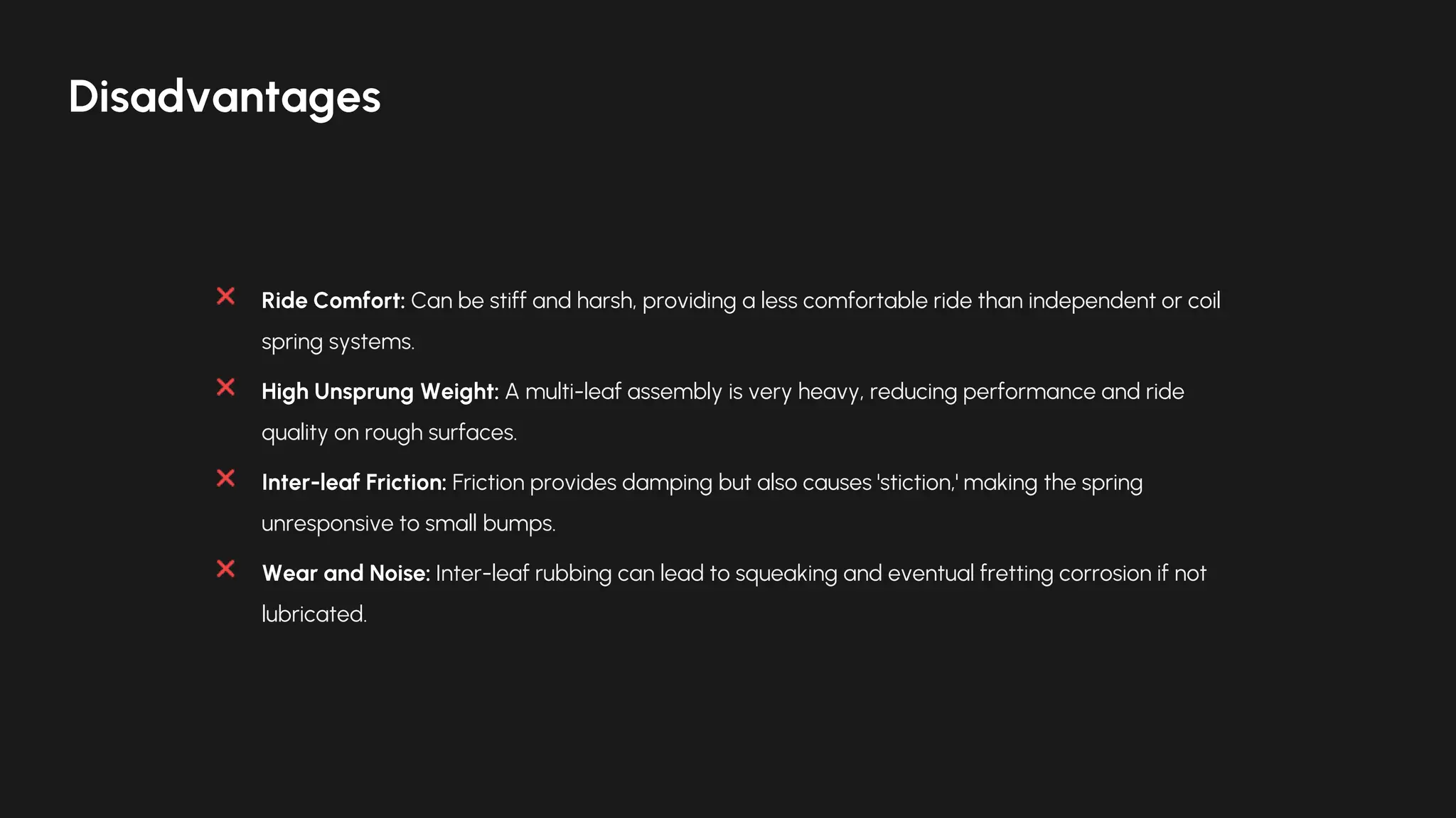
Ride Comfort: Canbe stiff and harsh, providing a less comfortable ride than independent or coil
spring systems.
High Unsprung Weight: A multi-leaf assembly is very heavy, reducing performance and ride
quality on rough surfaces.
Inter-leaf Friction: Friction provides damping but also causes 'stiction,' making the spring
unresponsive to small bumps.
Wear and Noise: Inter-leaf rubbing can lead to squeaking and eventual fretting corrosion if not
lubricated.
Disadvantages
16.
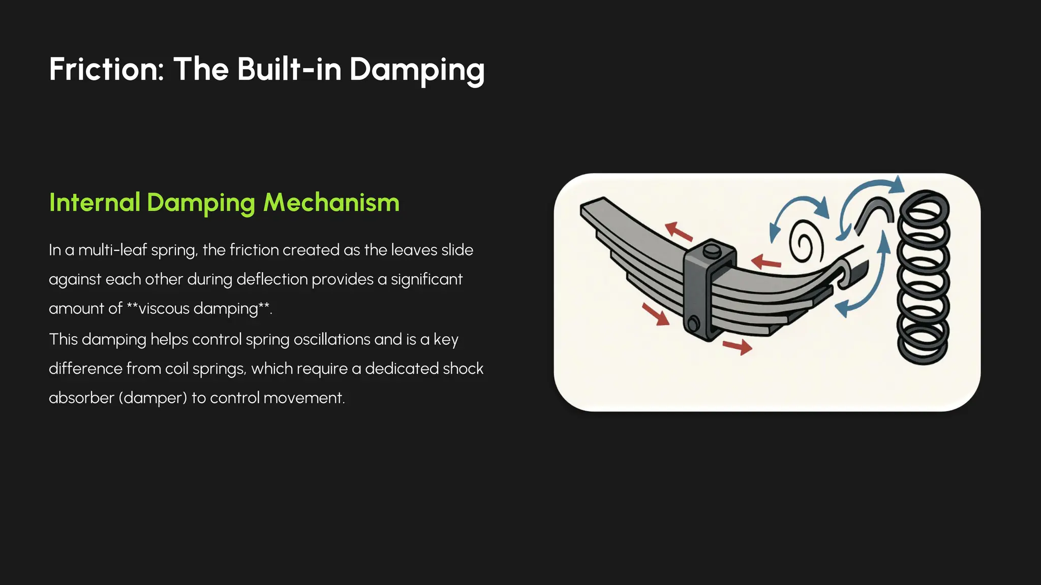
Internal Damping Mechanism
Ina multi-leaf spring, the friction created as the leaves slide
against each other during deflection provides a significant
amount of **viscous damping**.
This damping helps control spring oscillations and is a key
difference from coil springs, which require a dedicated shock
absorber (damper) to control movement.
Friction: The Built-in Damping
17.
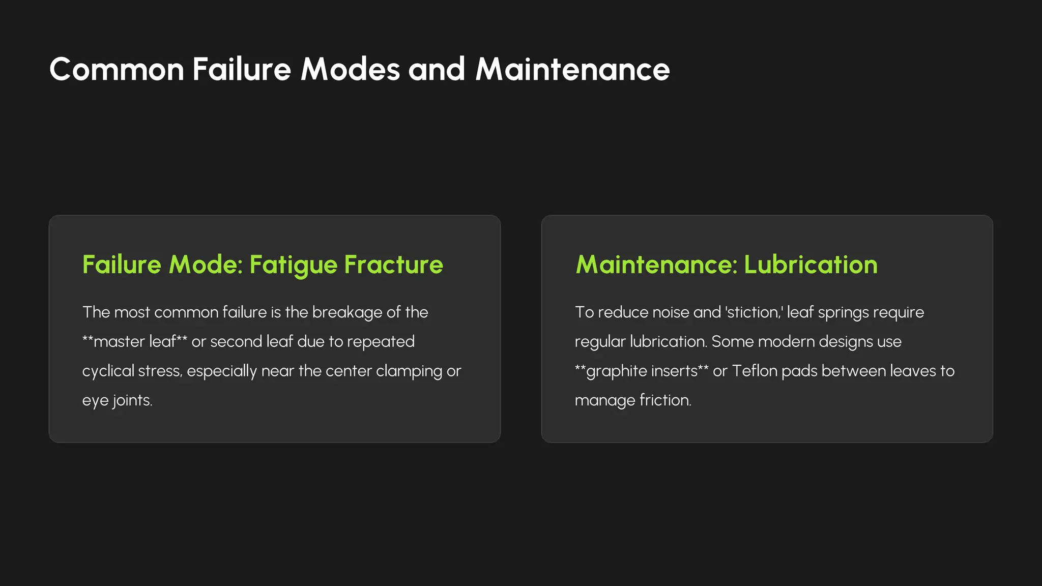
Failure Mode: FatigueFracture
The most common failure is the breakage of the
**master leaf** or second leaf due to repeated
cyclical stress, especially near the center clamping or
eye joints.
Maintenance: Lubrication
To reduce noise and 'stiction,' leaf springs require
regular lubrication. Some modern designs use
**graphite inserts** or Teflon pads between leaves to
manage friction.
Common Failure Modes and Maintenance
18.
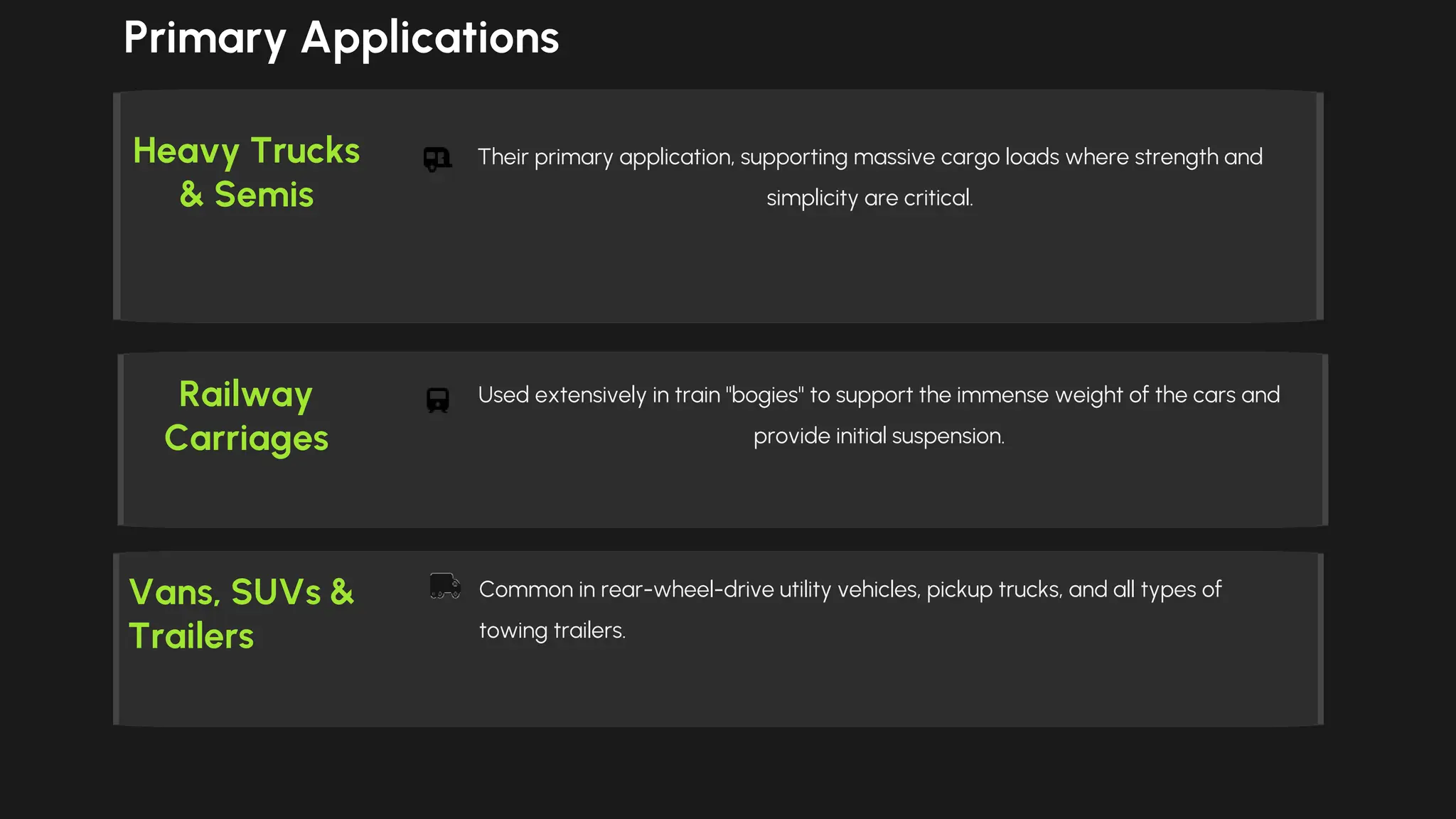
Heavy Trucks
& Semis
Theirprimary application, supporting massive cargo loads where strength and
simplicity are critical.
Vans, SUVs &
Trailers
Common in rear-wheel-drive utility vehicles, pickup trucks, and all types of
towing trailers.
Railway
Carriages
Used extensively in train "bogies" to support the immense weight of the cars and
provide initial suspension.
Primary Applications
19.
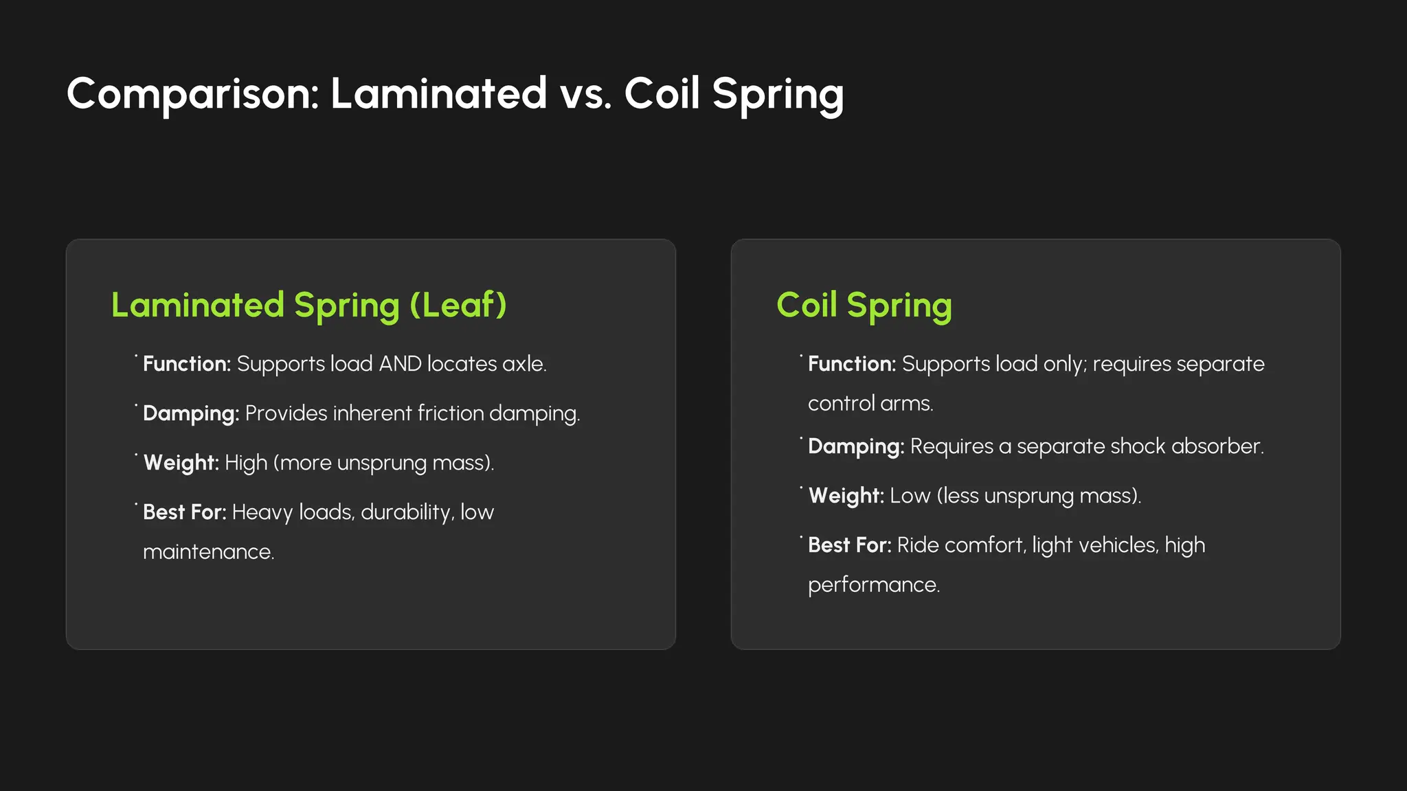
Laminated Spring (Leaf)Coil Spring
• Function: Supports load AND locates axle.
• Damping: Provides inherent friction damping.
• Weight: High (more unsprung mass).
• Best For: Heavy loads, durability, low
maintenance.
• Function: Supports load only; requires separate
control arms.
• Damping: Requires a separate shock absorber.
• Weight: Low (less unsprung mass).
• Best For: Ride comfort, light vehicles, high
performance.
Comparison: Laminated vs. Coil Spring
20.
Newer designs useFiber-Reinforced
Plastic (FRP) to slash weight while
maintaining strength, ensuring the
laminated spring remains a viable
suspension option.
— Advanced Material
Application
"
"
Modern Relevance: The Composite Future
21.
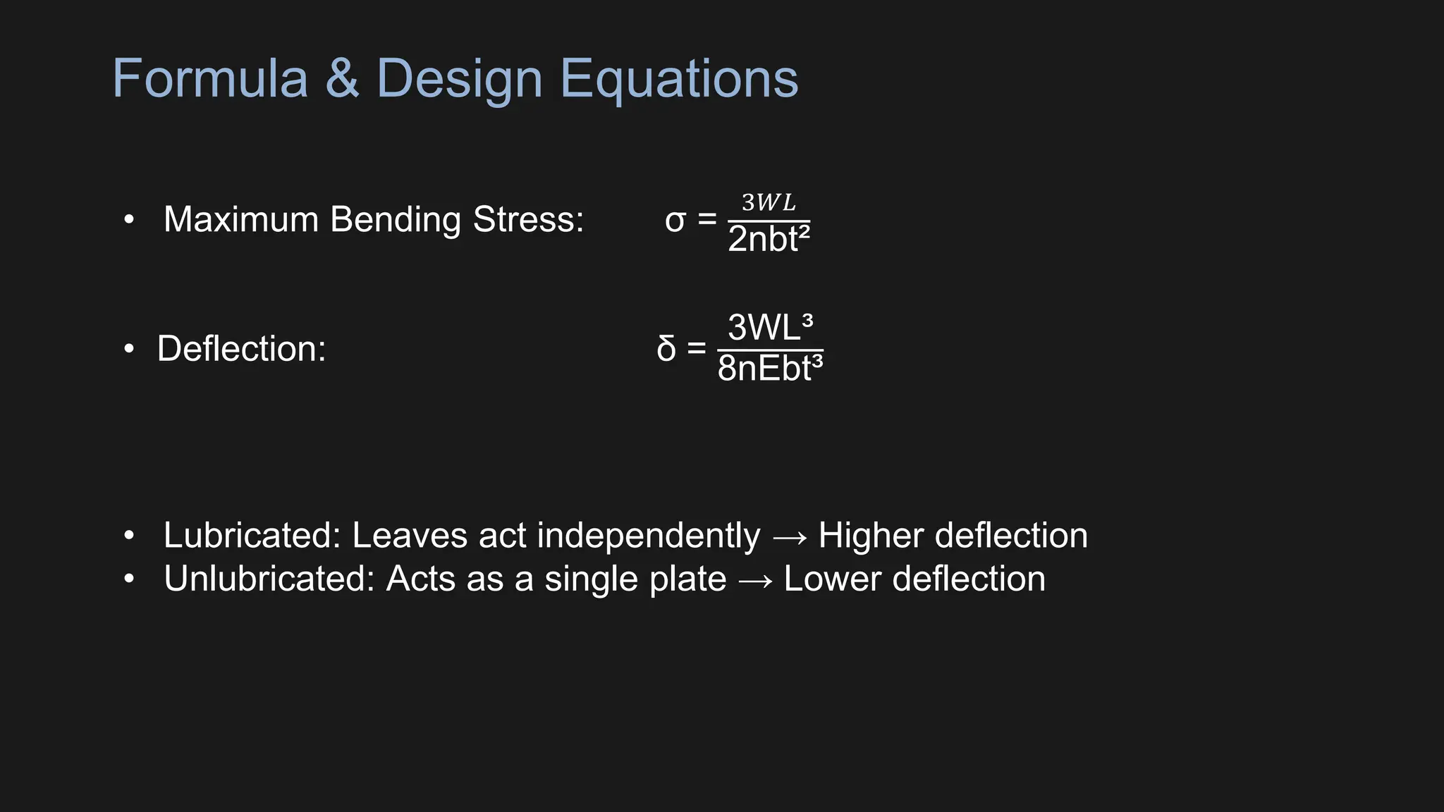
Formula & DesignEquations
• Maximum Bending Stress: σ =
3𝑊𝐿
2nbt²
• Deflection: δ =
3WL³
8nEbt³
• Lubricated: Leaves act independently → Higher deflection
• Unlubricated: Acts as a single plate → Lower deflection
22.
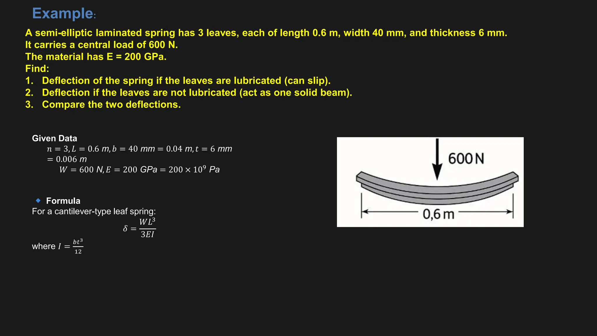
A semi-elliptic laminatedspring has 3 leaves, each of length 0.6 m, width 40 mm, and thickness 6 mm.
It carries a central load of 600 N.
The material has E = 200 GPa.
Find:
1. Deflection of the spring if the leaves are lubricated (can slip).
2. Deflection if the leaves are not lubricated (act as one solid beam).
3. Compare the two deflections.
Example:
Given Data
𝑛 = 3, 𝐿 = 0.6 m, 𝑏 = 40 mm = 0.04 m, 𝑡 = 6 mm
= 0.006 m
𝑊 = 600 N, 𝐸 = 200 GPa = 200 × 109
Pa
Formula
For a cantilever-type leaf spring:
𝛿 =
𝑊𝐿3
3𝐸𝐼
where 𝐼 =
𝑏𝑡3
12
23.
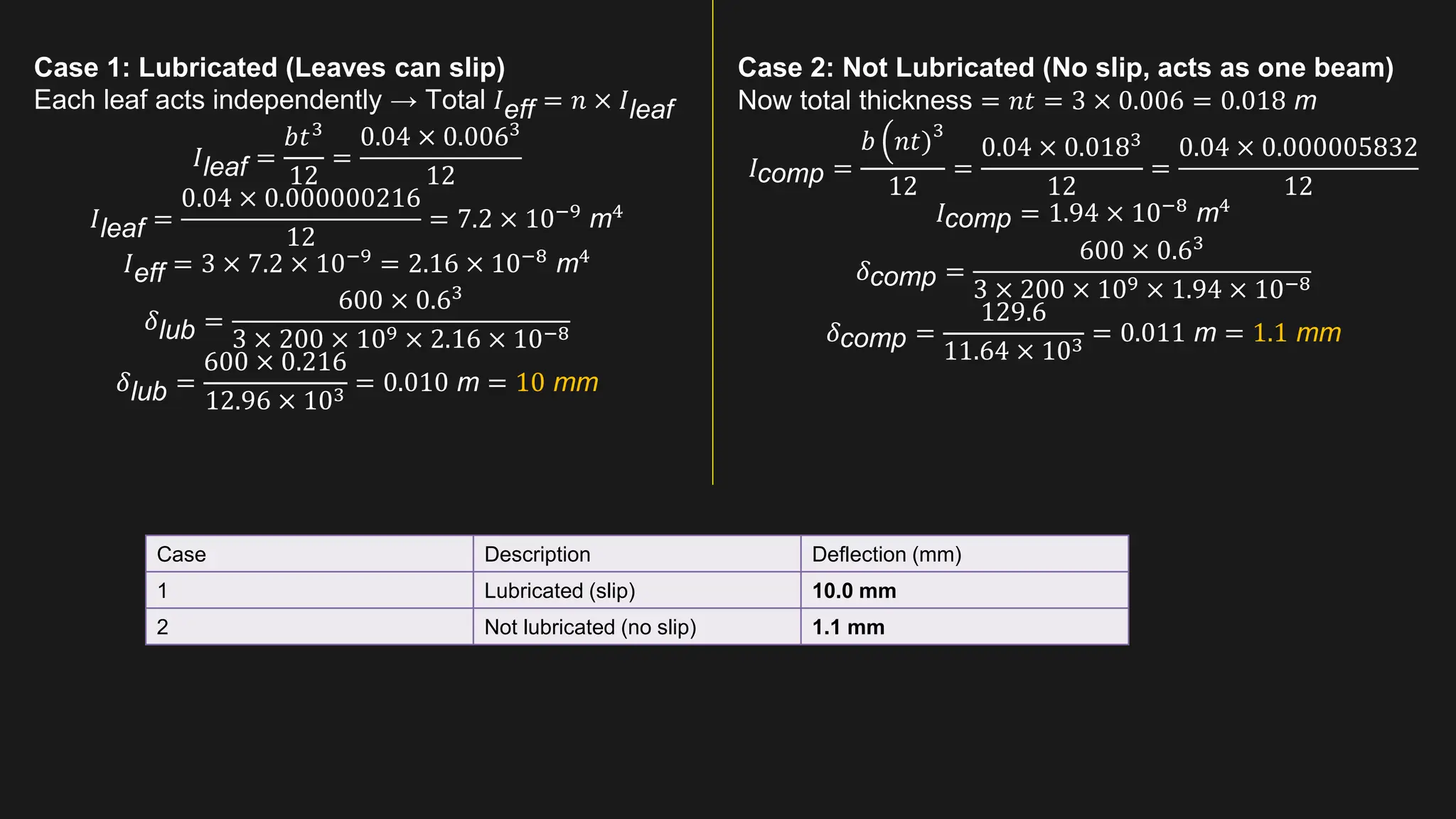
Case 1: Lubricated(Leaves can slip)
Each leaf acts independently → Total 𝐼eff = 𝑛 × 𝐼leaf
𝐼leaf =
𝑏𝑡3
12
=
0.04 × 0.0063
12
𝐼leaf =
0.04 × 0.000000216
12
= 7.2 × 10⁻⁹
m4
𝐼eff = 3 × 7.2 × 10−9
= 2.16 × 10⁻⁸
m4
𝛿lub =
600 × 0.63
3 × 200 × 109 × 2.16 × 10−8
𝛿lub =
600 × 0.216
12.96 × 103 = 0.010 m = 10 mm
Case 2: Not Lubricated (No slip, acts as one beam)
Now total thickness = 𝑛𝑡 = 3 × 0.006 = 0.018 m
𝐼comp =
𝑏 ቀ𝑛𝑡)3
12
=
0.04 × 0.0183
12
=
0.04 × 0.000005832
12
𝐼comp = 1.94 × 10⁻⁸
m4
𝛿comp =
600 × 0.63
3 × 200 × 109 × 1.94 × 10−8
𝛿comp =
129.6
11.64 × 103 = 0.011 m = 1.1 mm
Case Description Deflection (mm)
1 Lubricated (slip) 10.0 mm
2 Not lubricated (no slip) 1.1 mm


![Laminated_Springs[1]. Machine design practice](https://image.slidesharecdn.com/laminatedsprings1-251116120255-2a3c06fb/75/Laminated_Springs-1-Machine-design-practice-25-2048.jpg)


![Laminated_Springs[1]. Machine design practice](https://crownmelresort.com/image.slidesharecdn.com/laminatedsprings1-251116120255-2a3c06fb/75/Laminated_Springs-1-Machine-design-practice-25-2048.jpg)