Downloaded 106 times


![General Specifications
E100, E110, E120, E130, E140, E150, E160, E170, E180
Lawn Tractors
10-20-3
TM151119 (01.12.2018)
application.
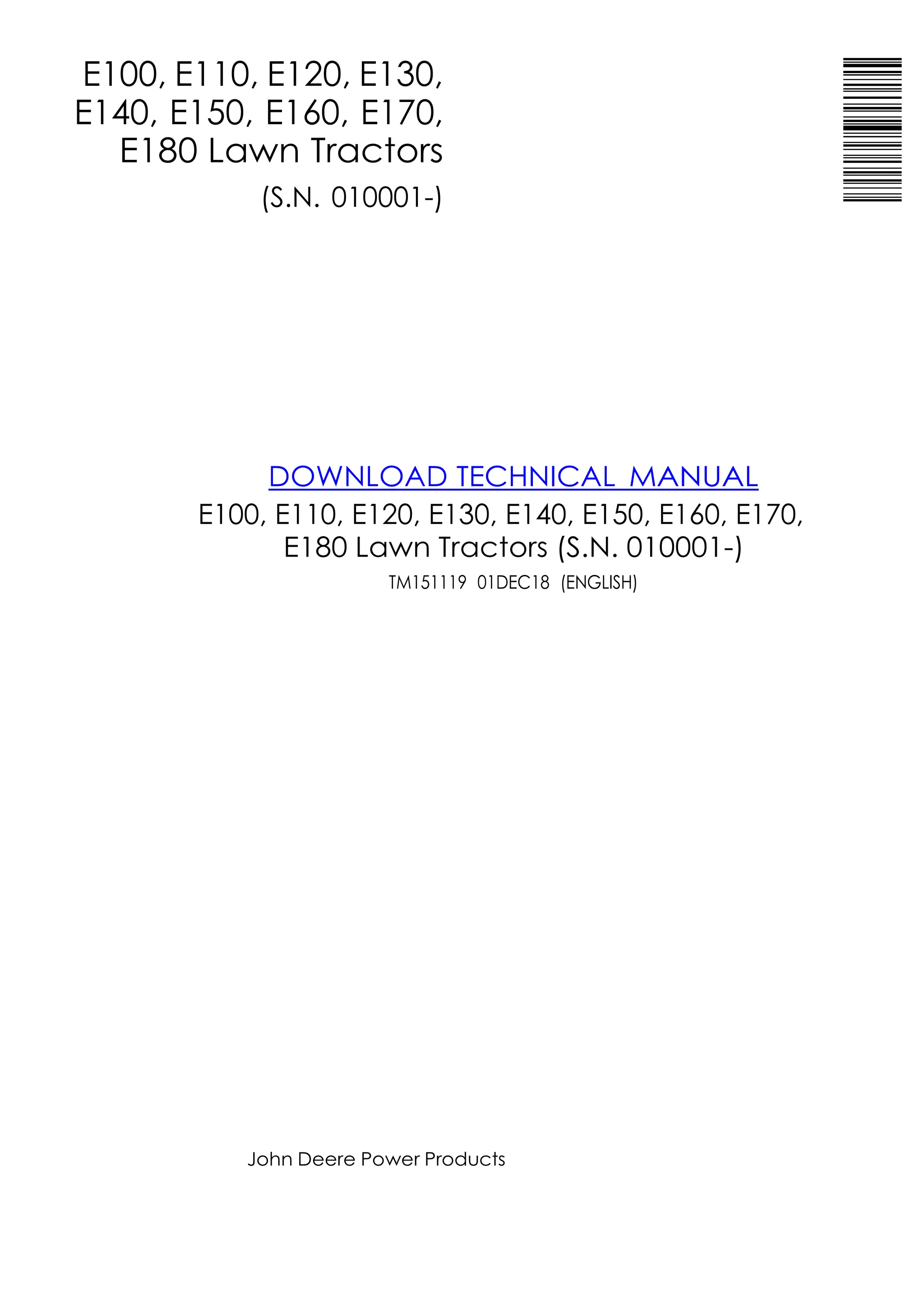
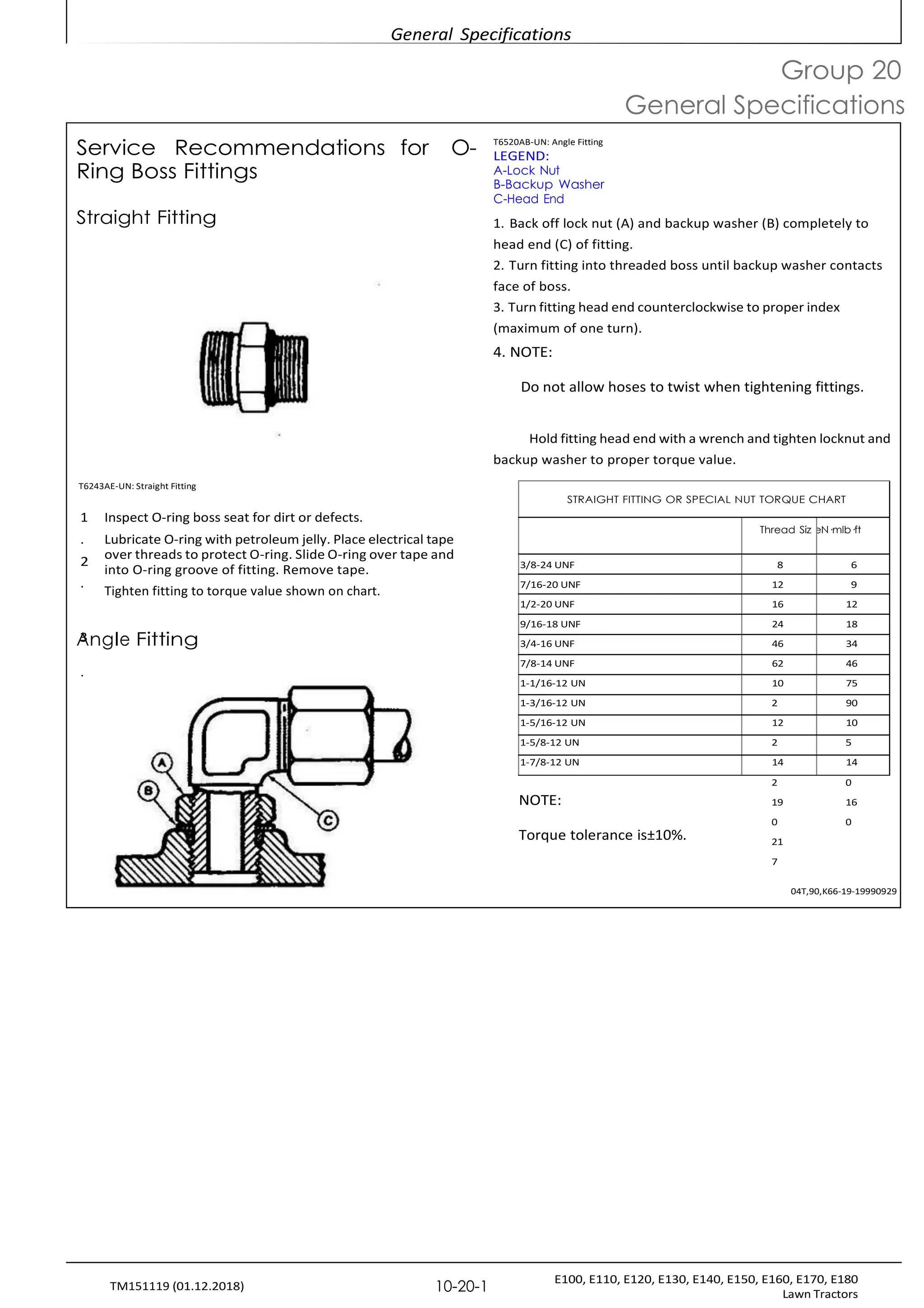
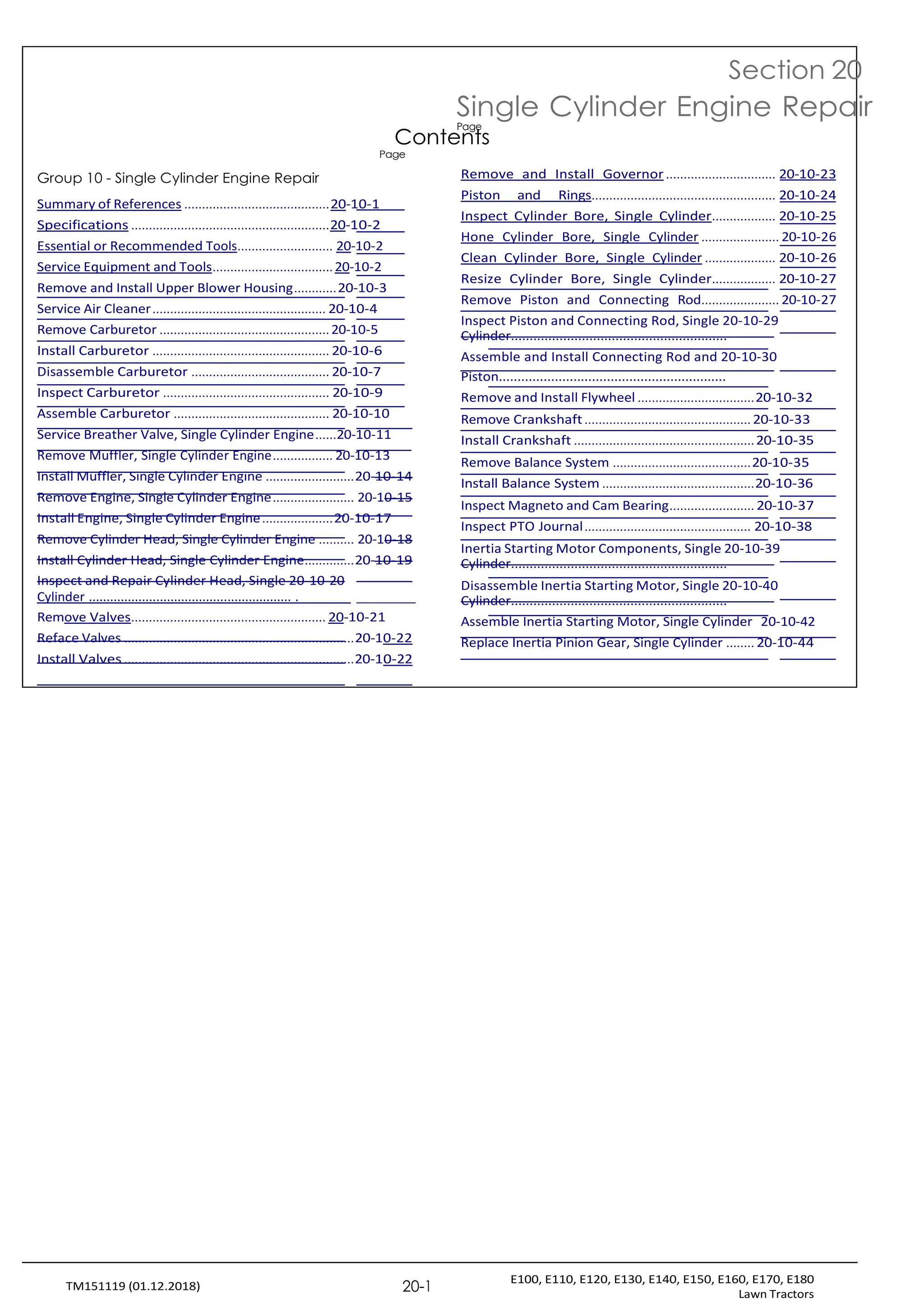
Metric Bolt and Screw Torque Values
TS1670-UN: Metric Bolt and Screw
Class 4.8Class 8.8 or 9.8Class 10.9Class 12.9
Lubricated Dry Lubricated Dry Lubricated Dry Lubricated Dry
[‘Lubricated”means [‘Dry”means [‘Lubricated”means [‘Dry”means [‘Lubricated”means [‘Dry”means [‘Lubricated”means [‘Dry”means
Boltcoated with a lubricantplain or zinccoated with a lubricantplain or zinccoated with a lubricantplain or zinccoated with a lubricantplain or zinc
orsuch as engine oil,plated withoutsuch as engine oil,plated withoutsuch as engine oil,plated withoutsuch as engine oil,plated without
Screwfasteners withanyfasteners withanyfasteners withanyfasteners withany
c
So
iza
etp
in
hg
os
s,p
o
h
ra
M
te
20
an
ad
nd
oM
illu
6b
tr
o
ic
M
at
1i
8
o
c
n
o
,a
o
tr
in
pg
ho
s,so
prhM
at
2
e
0aa
n
n
d
do
M
il6
lut
b
oriM
ca
18
tic
oo
na
, t
o
i
n
r
p
g
h
s
o
,o
s
p
rh
M
a
2
t
0
eandM
oi
6
llu
to
br
M
ic
1a
8t
c
ion
at
,io
n
r
g
p
s
h
,os
rp
M
h2
a
0
te
aa
nn
dd
Mo
6ilt
lo
ub
M
ri
1c
8
ation, o
r
larger fasteners withfasteners withlarger fasteners withfasteners withlarger fasteners withfasteners withlarger fasteners withfasteners with
JDM F13C, F13F or F13JJDM F13B,JDM F13C, F13F or F13JJDM F13B,JDM F13C, F13F or F13JJDM F13B,JDM F13C, F13F or F13JJDM F13B,
zinc flake coating.]F13E or F13Hzinc flake coating.]F13E or F13Hzinc flake coating.]F13E or F13Hzinc flake coating.]F13E or F13H
zinc flakezinc flakezinc flakezinc flake
coating.] coating.] coating.] coating.]
N˙m lb.-in. N˙m lb.-in. N˙m lb.-in. N˙m lb.-in. N˙m lb.-in. N˙m lb.-in. N˙m lb.-in. N˙m lb.-in.
M6 4.7 42 6 53 8.9 79 11.3 100 13 115 16.5 146 15.5 137 19.5 172
N˙m lb.-ft. N˙m lb.-ft. N˙m lb.-ft. N˙m lb.-ft.
N˙m lb.-ft. N˙m lb.-ft. N˙m lb.-ft.
N˙m lb.-ft.
M8 11.5 102 14.5 128 22 194 27.5 243 32 23.5 40 29.5 37 27.5 47 35
M10 23 204 29 21 43 32 55 40 63 46 80 59 75 55 95 70
M12 40 29.5 50 37 75 55 95 70 110 80 140 105 130 95 165 120
M14 63 46 80 59 120 88 150 110 175 130 220 165 205 150 260 190
M16 100 74 125 92 190 140 240 175 275 200 350 255 320 235 400 300
M18 135 100 170 125 265 195 330 245 375 275 475 350 440 325 560 410
M20 190 140 245 180 375 275 475 350 530 390 675 500 625 460 790 580
M22 265 195 330 245 510 375 650 480 725 535 920 680 850 625 1080 800
M24 330 245 425 315 650 480 820 600 920 680 1150 850 1080 800 1350 1000
M27 490 360 625 460 950 700 1200 885 1350 1000 1700 1250 1580 1160 2000 1475
M30 660 490 850 625 1290 950 1630 1200 1850 1350 2300 1700 2140 1580 2700 2000
M33 900 665 1150 850 1750 1300 2200 1625 2500 1850 3150 2325 2900 2150 3700 2730
M36 1150 850 1450 1075 2250 1650 2850 2100 3200 2350 4050 3000 3750 2770 4750 3500
Torque values listed are for general use only, based on the strength of the bolt or
screw. DO NOT use these values if a different torque value or tightening
Shear bolts are designed to fail under predetermined loads. Always replace shear bolts with
identical property class. Replace fasteners with the same or higher property class. If higher
p
ro
c
p
e
d
rt
u
y
re
c
l
i
a
s
s
g
s
i
f
v
a
en
te
f
o
n
r
e
a
rs
s
a
p
r
e
e
c
u
i
f
s
ic
ed
a
,
p
t
p
i
g
l
i
h
c
a
te
ti
n
on
h
.
e
F
s
o
e
r
t
s
o
tainl
es
t
s
re
s
n
te
g
e
th
lf
o
a
f
s
th
e
e
n
e
o
r
r
s
i
g
o
in
r
a
f
o
l
.
r
Makes
u
re
n
f
a
u
s
t
t
s
e
o
n
n
e
r
U
t
-
h
b
r
o
e
a
l
t
d
s
,
s
s
a
e
r
e
t
c
h
l
e
e
a
t
n
i
g
a
h
n
t
e
d
n
t
i
h
n
a
g
t
i
n
y
o
s
t
u
r
u
p
c
r
o
t
i
p
o
e
n
r
s
l
y
f
o
s
r
t
a
t
h
r
t
e
t
s
h
p
r
e
a
c
i
d
f
i
e
c
n
a
g
p
a
p
g
l
i
e
c
m
a
t
e
i
o
n
n
t
.
.
W
Ti
h
gh
e
t
n
e
p
n
ossible,
l
p
u
l
b
a
s
ri
t
c
i
c
a
t
i
e
n
s
p
e
l
a
rt
i
n
o
r
o
c
r
r
z
i
i
m
n
c
p
e
p
d
l
a
s
t
e
te
d
e
f
l
a
t
s
y
t
p
e
e
n
e
l
o
r
c
s
k
o
n
th
u
e
ts
rt
b
h
y
a
t
n
u
l
r
o
n
c
i
n
k
g
n
t
u
h
t
e
s
,
n
w
u
tt
o
e
l
th
b
e
ol
d
ts
ry
o
t
r
o
w
rq
h
u
e
e
e
ln
u
ts
,
s
u
h
n
ol
e
ws
n
sd
i
n
i
f
t
f
h
ee
r
ec
n
h
t
ai
n
r
ts
,
tu
ru
n
c
l
e
ti
s
os
n
d
s
i
f
a
f
re
e
re
g
n
i
v
t
ei
n
n
s
f
to
r
r
u
t
c
h
ti
eon
s
p
s
ea
c
ri
ef
i
c
g
i
av
p
en
p
l
f
i
c
o
a
rt
ti
h
oen
.
s
p
e
c
i
f
i
c
DX,TORQ2-19-20110112](https://image.slidesharecdn.com/johndeeree100e110e120servicemanual-250502151918-f9d6f69b/75/John-Deere-E100-E110-E120-Service-manual-pdf-15-2048.jpg)
![General Specifications
E100, E110, E120, E130, E140, E150, E160, E170, E180
Lawn Tractors
10-20-4
TM151119 (01.12.2018)
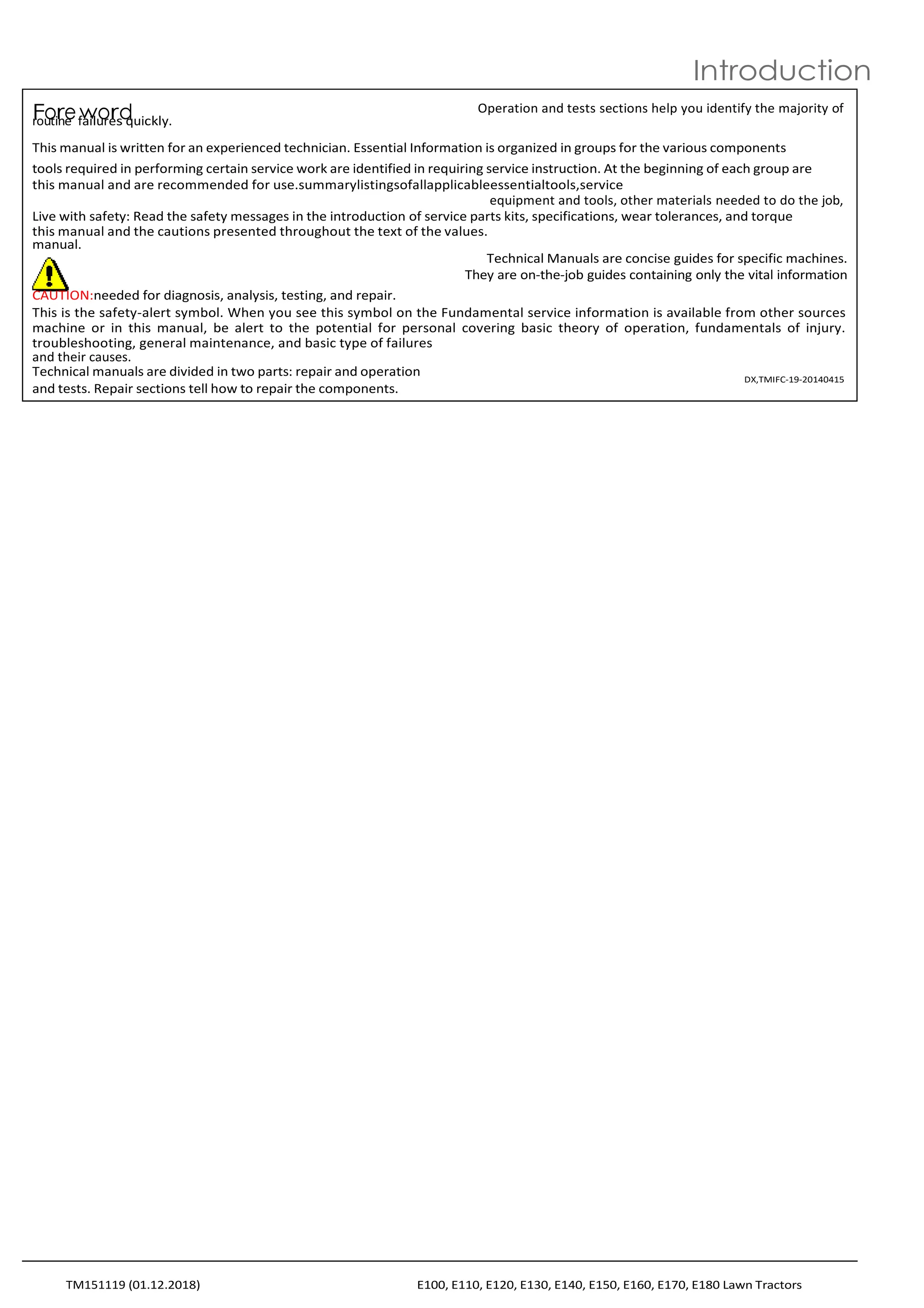
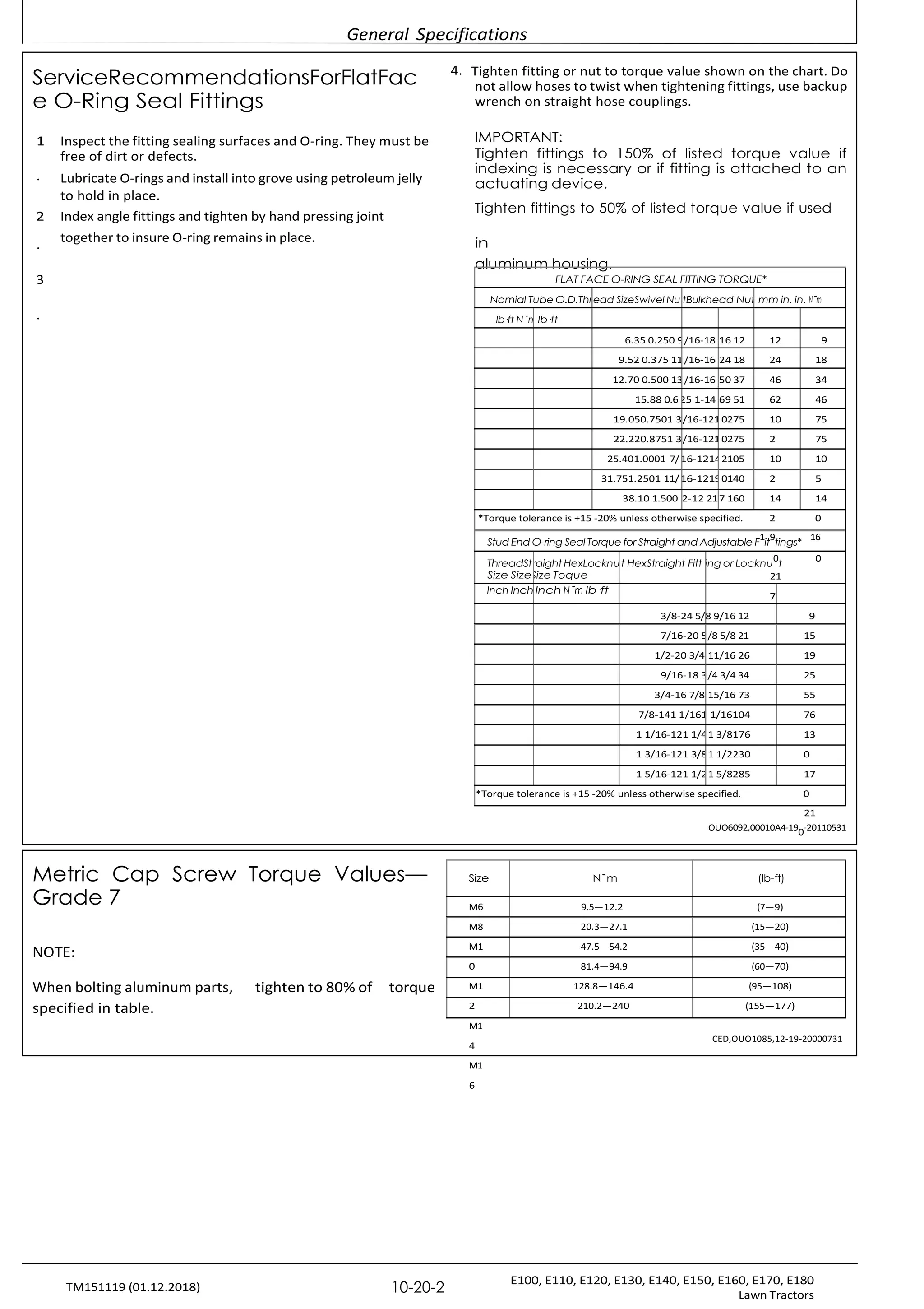
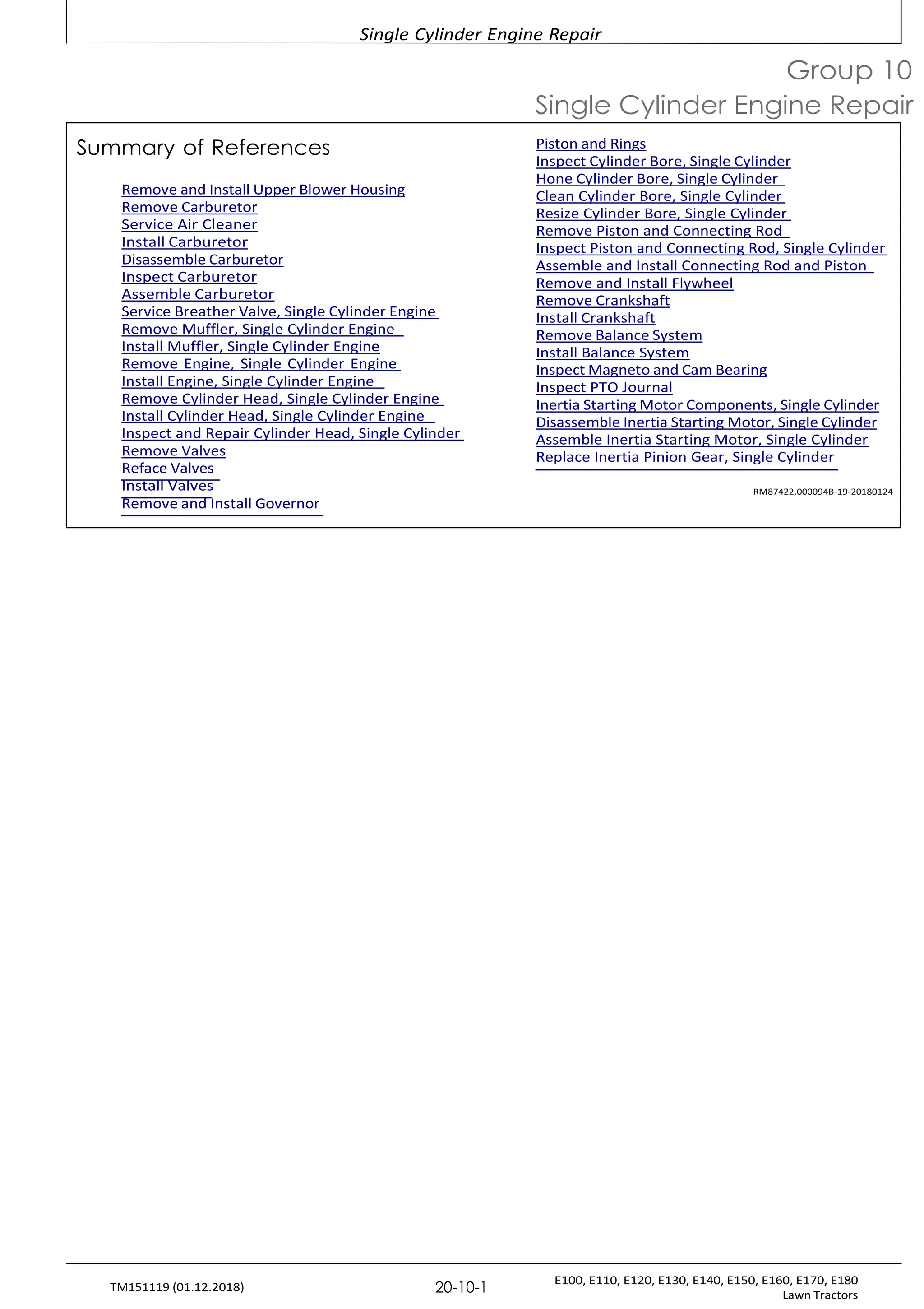
Unified Inch Bolt and Screw Torque Values
TS1671-UN: Unified Inch Bolt and Screw
SAE Grade 2 [Grade 2 applies for hex
cap screws (not hex bolts) up to 6 in.
(152 mm) long. Grade 1 applies for
S
h
A
e
x
Ec
G
arp
ad
sc
er1
e
S
w
As
Eo
G
vr
e
a
rd
6
ein
5,. 5
(
1
.
5
12
or
m
5m
.2S
) A
E G
r
a
d
e 8 o
r 8
.
2
long, and for all other types of bolts
and screws of any length.]
Bolt Lubricated Dry Lubricated Dry Lubricated Dry Lubricated Dry
or [‘Lubricated”means [‘Dry”means [‘Lubricated”means [‘Dry”means [‘Lubricated”means [‘Dry”means [‘Lubricated”means [‘Dry”means
Screwcoated with a lubricantplain or zinccoated with aplain or zinccoated with aplain or zinccoated with a lubricantplain or zinc
Sizesuch as engine oil,plated withoutlubricant such asplated withoutlubricant such asplated withoutsuch as engine oil,plated without
fasteners withanyengine oil, fastenersanyengine oil, fastenersanyfasteners withany
phosphate and oillubrication, orwith phosphate andlubrication, orwith phosphate andlubrication, orphosphate and oillubrication, or
coatings, or 7/8 in. and1/4 to 3/4 in.oil coatings, or 7/8 in.1/4 to 3/4 in.oil coatings, or 7/8 in.1/4 to 3/4 in.coatings, or 7/8 in. and1/4 to 3/4 in.
larger fasteners withfasteners withand larger fastenersfasteners withand larger fastenersfasteners withlarger fasteners withfasteners with
JDM F13C, F13F or F13JJDM F13B,with JDM F13C, F13FJDM F13B,with JDM F13C, F13FJDM F13B,JDM F13C, F13F or F13JJDM F13B,
zinc flake coating.]F13E or F13Hor F13J zinc flakeF13E or F13Hor F13J zinc flakeF13E or F13Hzinc flake coating.]F13E or F13H
zinc flakecoating.]zinc flakecoating.]zinc flakezinc flake
coating.] coating.] coating.] coating.]
N˙m lb.-in. N˙m lb.-in. N˙m lb.-in. N˙m lb.-in. N˙m lb.-in. N˙m lb.-in. N˙m lb.-in. N˙m lb.-in.
1/4 3.7 33 4.7 42 6 53 7.5 66 9.5 84 12 106 13.5 120 17 150
5/16 7.7 68 9.8 86 12 106 15.5 137 19.5 172 25 221 28 20.5 35 26
N˙m lb.-ft. N˙mlb.-ft.
N˙m lb.-ft. N˙m lb.-ft.
3/8 13.5 120 17.5 155 22 194 27 240 35 26 44 32.5 49 36 63 46
N˙m lb.-ft. N˙m lb.-ft. N˙m lb.-ft.
7/16 22 194 28 20.5 35 26 44 32.5 56 41 70 52 80 59 100 74
N˙m lb.-ft.
1/2 34 25 42 31 53 39 67 49 85 63 110 80 120 88 155 115
9/16 48 35.5 60 45 76 56 95 70 125 92 155 115 175 130 220 165
5/8 67 49 85 63 105 77 135 100 170 125 215 160 240 175 305 225
3/4 120 88 150 110 190 140 240 175 300 220 380 280 425 315 540 400
7/8 190 140 240 175 190 140 240 175 490 360 615 455 690 510 870 640
1 285 210 360 265 285 210 360 265 730 540 920 680 1030 760 1300 960
1-1/8 400 300 510 375 400 300 510 375 910 670 1150 850 1450 1075 1850 1350
1-1/4 570 420 725 535 570 420 725 535 1280 945 1630 1200 2050 1500 2600 1920
1-3/8 750 550 950 700 750 550 950 700 1700 1250 2140 1580 2700 2000 3400 2500
1-1/2 990 730 1250 930 990 730 1250 930 2250 1650 2850 2100 3600 2650 4550 3350
Torque values listed are for general use only, based on the strength of the bolt or screw.
R
D
e
O
p
N
l
a
O
c
T
e
u
f
a
s
s
e
t
e
t
h
n
e
s
r
s
e
w
v
a
i
t
l
h
u
e
t
h
s
e
i
f
s
a
a
d
m
i
f
e
f
e
o
r
r
e
h
n
i
t
g
t
h
o
e
r
q
r
u
g
r
e
a
v
d
a
e
l
.
u
I
e
f
o
h
r
i
g
t
h
i
g
e
h
r
t
g
e
r
n
a
i
d
n
e
g
f
p
a
r
s
o
t
c
e
e
n
d
e
u
r
r
s
e
a
i
r
e
g
i
v
e
n f
o
r a
u
sp
s
e
d
ci
,
f
t
ic
ig
a
h
p
te
p
n
l
ic
t
a
h
t
e
i
o
s
e
n
.
t
F
o
o
t
r
h
p
e
l
s
a
t
s
r
t
e
i
c
ng
in
th
se
o
r
f
t
t
o
h
r
e
c
o
ri
r
m
ig
p
in
e
a
d
l
.
s
M
te
a
e
k
l
e
ty
s
p
u
e
re
l
o
f
c
a
k
s
t
n
e
u
n
t
e
s
r
,
t
f
h
or
e
s
a
ta
d
i
s
n
a
l
e
r
s
e
ss
teelclean and that you properly start thread engagement. When possible, lubricate plain
f
o
a
r
s
z
t
i
en
n
c
ep
r
s
l
a
,
to
e
rd
f
of
a
rs
n
tu
etn
s
e
o
rs
n
o
U
t-
h
b
e
o
rl
th
s
,
as
n
el
e
oc
th
k
en
u
ti
tg
s
h
,t
w
en
h
i
en
eg
li
b
n
os
l
t
t
rs
u
c
ot
r
i
o
wn
h
s
ef
e
ol
rn
tu
h
t
es
,
s
u
p
n
e
l
c
ei
f
s
i
s
ca
p
p
l
i
c
at
i
on
.
dSihffee
arrebnotlitnssatrrue
cdtieosnigsnaerde gtoiv
feanil
fuonrdtheer psrpeedceifti
ecr
ampipnleicdaltoi
oand.s. Always r
eplace shear bolts
DX,TORQ1-19-20110112
with identical grade.](https://image.slidesharecdn.com/johndeeree100e110e120servicemanual-250502151918-f9d6f69b/75/John-Deere-E100-E110-E120-Service-manual-pdf-16-2048.jpg)
![Fuel and Lubricants
E100, E110, E120, E130, E140, E150, E160, E170, E180
Lawn Tractors
10-15-3
TM151119 (01.12.2018)
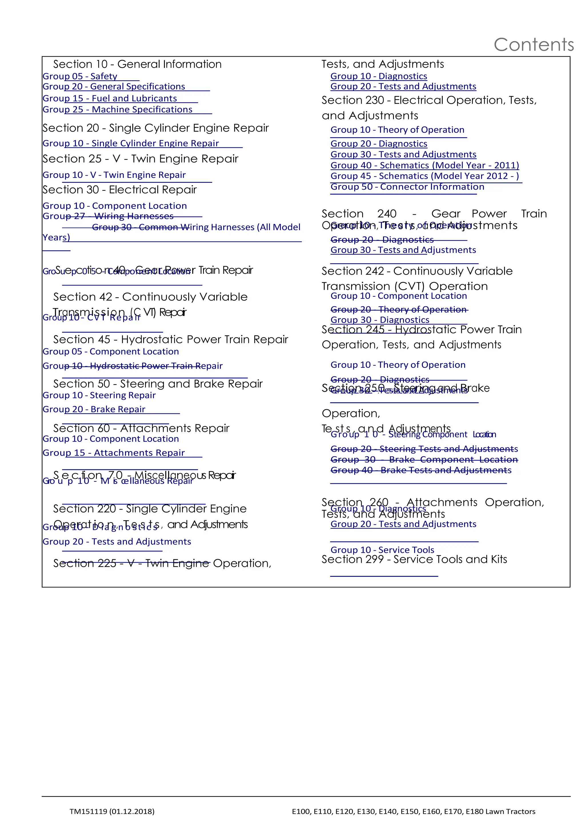
Gasoline Fuel for 4-Cycle Engines
Use unleaded gasoline with a minimum octane rating of 87 AKI
(anti-knock index) or 90 RON (research octane number).
Refuel outdoors. DO NOT smoke while you fill the fuel tank
or service the fuel system. Store fuel in properly identified
polyethylene containers.
Gasoline fuels specified to EN 228 or ASTM D4814 are
When storing fuel, add John Deere Gasoline Conditioner and
recommended.
Stabilizer (or equivalent) at the specified concentration.
Fuel blends of unleaded gasoline with a maximum 10% ethanol
or 15% MTBE (methyl tertiary-butyl ether) are also acceptable.
CAUTION:
Reduce the risk of fire. Handle fuel carefully. DO NOT fill
the fuel tank when the engine is running or hot. Stop
engine and allow it to cool for several minutes before filling
fuel tank. Fill fuel tank only to the bottom of the filler neck.
IMPORTANT:
DO NOT use methanol or fuel blends that contain methanol.
Avoid spilling fuel. Gasoline can damage plastic and painted
surfaces.
DO NOT mix oil with gasoline.
DX,FUEL2-19-20130515
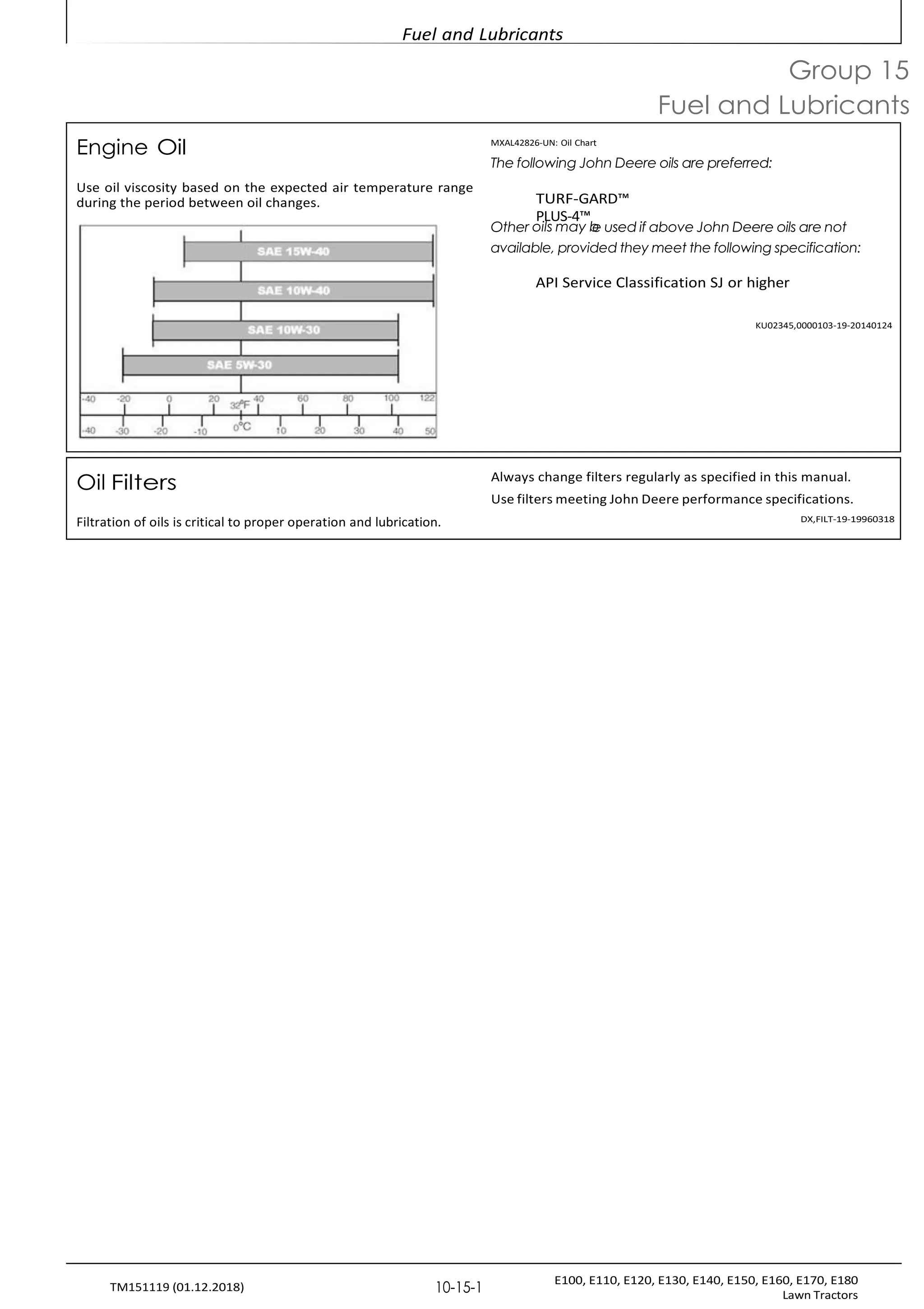
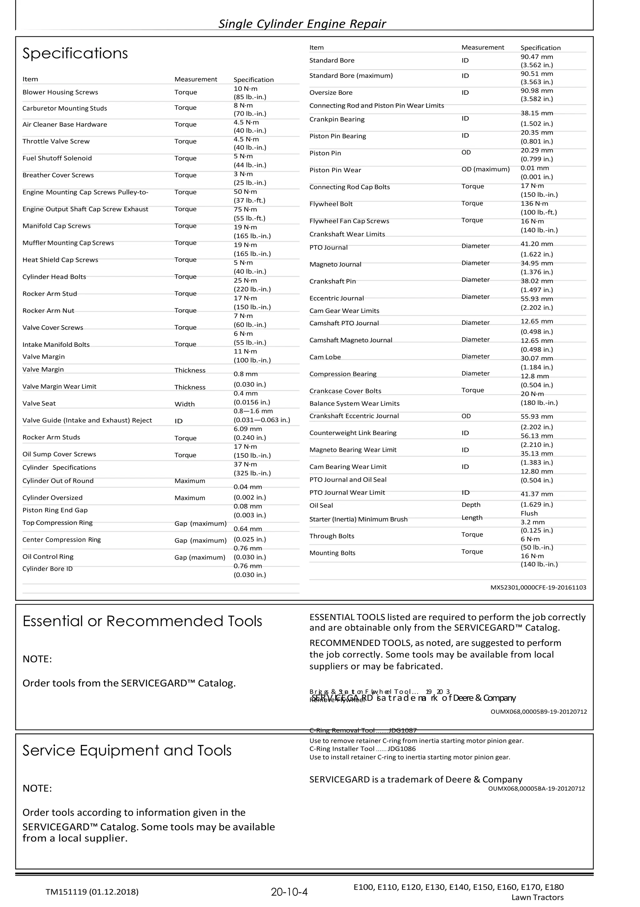
Transmission and Hydraulic Oil TS1739-UN: Oils for Air Temperature Ranges
Use oil viscosity based on the expected air temperature range
during the period between oil changes.
The following oils are preferred:
John Deere Hy-Gard™
John Deere Low Viscosity Hy-Gard™
Other oils may be used if they meet one of the following:
John Deere Standard JDM J20C
John Deere Standard JDM J20D
Use John Deere Bio Hy-Gard™ II oil when a biodegradable
fluid is required. [Bio Hy-Gard II meets or exceeds the minimum
biodegradability of 80% within 21 days according to CEC-
L-33-T-82 test method. Bio Hy-Gard II should not be mixed with
mineral oils, because this reduces the biodegradability and
makes proper oil recycling impossible.]
Hy-Gard is a trademark of Deere & Company
Bio Hy-Gard is a trademark of Deere & Company
DX,ANTI-19-20160825
Grease
IMPORTANT:
Avoid Damage! Use recommended John Deere greases
to avoid component failure and premature wear.
The following grease is recommended for service:
John Deere Multi-Purpose HD Lithium Complex
Grease
t
M
hes
ix
e a
in
dd
g
itivo
esfan
L
d
u
de
b
gr
ra
id
c
ea
lu
n
brt
ic
s
ant p
e
r
f
o
r
m
a
n
c
e
.
Grease-Gard™ Premium Plus
Not all grease types are compatible; John Deere does not
recommend mixing greases. If using any product other than the
recommended grease in service, purge any remaining grease
fromthesystempriortoapplication.Ifthisisnotpractical,grease
twice as often until all old grease is purged from the system.
OUMX068,0000642-19-20140827
Mixing different oils can interfere with the proper functioning of
In general, avoid mixing different brands or types of oil. Oil ConsultyourJohnDeeredealertoobtainspecificinformationand
manufacturers blend additives in their oils to meet certain recommendations.
specifications and performance requirements.DX,LUBMIX-19-19960318
Alternative and Synthetic Lubricants
Some John Deere brand coolants and lubricants may not be
available in your location.
Conditions in certain geographical areas may require lubricant Consult your John Deere dealer to obtain information and
recommendations different from those printed in this manual.recommendations.](https://image.slidesharecdn.com/johndeeree100e110e120servicemanual-250502151918-f9d6f69b/75/John-Deere-E100-E110-E120-Service-manual-pdf-19-2048.jpg)
![Fuel and Lubricants
E100, E110, E120, E130, E140, E150, E160, E170, E180
Lawn Tractors
10-15-5
TM151119 (01.12.2018)
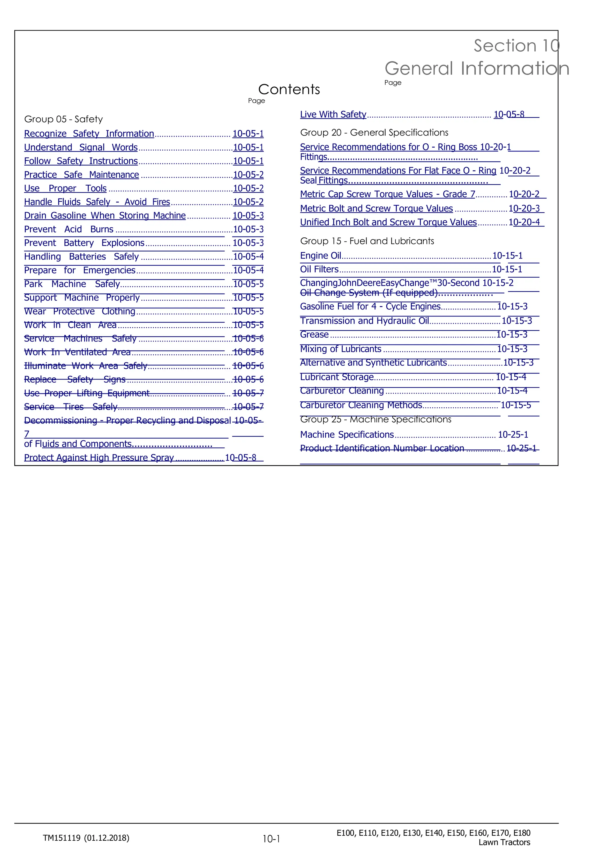
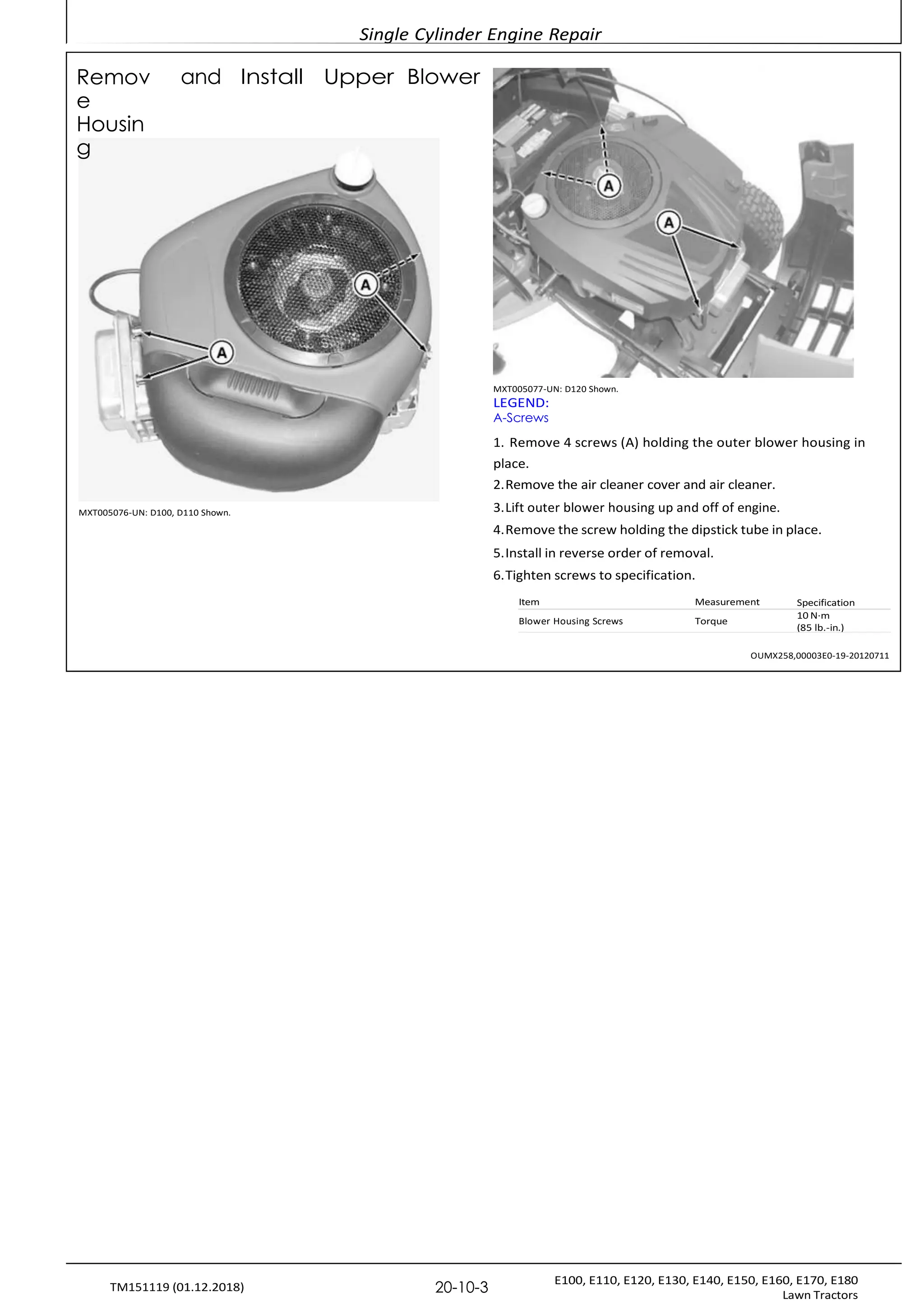
Carburetor Cleaning Methods
Ultrasonic Cleaning Systemsareas.
carburetor passages in the opposite direction of the air and fuel
flow (into the smallest passages to flush debris out of the larger
passages). This will prevent debris lodging in difficult to clean
UltrasoniccleanersuseenvironmentallyfriendlycleaningsolutionAerosol Cleaner
and sound waves to penetrate deep into carburetor passages.
Heating the solution is an option on ultrasonic cleaners that Personal safety, environmental concerns and cleaning
significantly increases the effectiveness of the system. Ultrasonic effectiveness make this method the least desirable. This method
cleaner systems work by creating sound wave pulses that are can be used on carburetor components that may be damaged
transmitted through a cleaning solution. Manufactures of by caustic cleaners (rubber seals or other non-metallic
ultrasonic cleaners claim the pulses create small bubbles that components). When cleaning with aerosol sprays, it is always
loosen and pulverizes contaminates. Select a chemical solution best to spray in the opposite direction of the air/fuel circuit (into
that is designed specifically for carburetor cleaning.thesmallestpassagestoflushdebrisoutofthelargerpassages).
This will prevent debris lodging in difficult to clean areas.
Generally, chemicals will need to be diluted with water prior to
use. When choosing a chemical, consider dilution rates to help
determine which chemical is the most cost effective. Consider
disposal of cleaning solution before ordering chemicals. Check CAUTION:
with local authorities on recommended disposal methods before Vapors from solvents can be explosive and flammable.
disposing of any cleaning solution. Ultrasonic cleaners come in Follow the instructions on the container label for safe use
manysizes.Most5.7—7.6L(1.5-2gal.)tankswillbesufficientof the solvent.
for carburetors used by John Deere gas engines.
IfanUltrasonicCleanerisused,placecarburetorinandrunforWork in a well-ventilated area.
30minutesat43.4°C(110°F)inthepropersolutionmix.IftheWear protective clothing when handling solvent.
solutionistoostrongorthecarburetorisleftinthecleanerfortooDo not smoke while handling solvents.
l
K
o
e
n
e
g,
p
th
s
e
ol
a
v
l
e
u
n
m
t
in
a
u
w
m
ay
bo
fr
d
o
y
m
wi
f
l
l
l
a
h
m
av
e
e
s
a
o
r
r
e
s
si
p
d
a
u
r
e
k
o
s
n thesur
facefrom
the aluminum oxidizing.
Rinse the parts in water and dry with compressed air (up to 210
kPa [30 psi]).Caustic Dip Tanks
CAUTION:cleaning needs.
Caustic dip tanks use aggressive chemicals to dissolve carbon
based contamination. This method is effective for most carburetor
Compressed air can cause debris to fly a long distanceRotatingthepartsinthetankwillensurethecleaningsolution
flushes out any air pockets left in the passages. Follow the
Clear work area of bystandersrecommendationonthecleanerforsubmersiontimes.
Wear eye protection when using compressed air for Disadvantages of the caustic dip tanks are that some carburetor
cleaning purposes.parts may be damaged if left in solution too long.
Reduce compressed air pressure to 210 kPa (30 Personal safety and chemical disposal are additional concerns.
psi). Because the chemical is caustic, exposure may cause injury or
death. Disposal of used solution can be difficult because most
cleaners are considered hazardous waste.
Wash off and blow ports out in carburetor body, fuel transfe OUMX258,0000307-19-20120524
tubes, and discharge port. Blow compressed air r
throug
h](https://image.slidesharecdn.com/johndeeree100e110e120servicemanual-250502151918-f9d6f69b/75/John-Deere-E100-E110-E120-Service-manual-pdf-21-2048.jpg)


![General Specifications
E100, E110, E120, E130, E140, E150, E160, E170, E180
Lawn Tractors
10-20-3
TM151119 (01.12.2018)
application.
Metric Bolt and Screw Torque Values
TS1670-UN: Metric Bolt and Screw
Class 4.8Class 8.8 or 9.8Class 10.9Class 12.9
Lubricated Dry Lubricated Dry Lubricated Dry Lubricated Dry
[‘Lubricated”means [‘Dry”means [‘Lubricated”means [‘Dry”means [‘Lubricated”means [‘Dry”means [‘Lubricated”means [‘Dry”means
Boltcoated with a lubricantplain or zinccoated with a lubricantplain or zinccoated with a lubricantplain or zinccoated with a lubricantplain or zinc
orsuch as engine oil,plated withoutsuch as engine oil,plated withoutsuch as engine oil,plated withoutsuch as engine oil,plated without
Screwfasteners withanyfasteners withanyfasteners withanyfasteners withany
c
So
iza
etp
in
hg
os
s,p
o
h
ra
M
te
20
an
ad
nd
oM
illu
6b
tr
o
ic
M
at
1i
8
o
c
n
o
,a
o
tr
in
pg
ho
s,so
prhM
at
2
e
0aa
n
n
d
do
M
il6
lut
b
oriM
ca
18
tic
oo
na
, t
o
i
n
r
p
g
h
s
o
,o
s
p
rh
M
a
2
t
0
eandM
oi
6
llu
to
br
M
ic
1a
8t
c
ion
at
,io
n
r
g
p
s
h
,os
rp
M
h2
a
0
te
aa
nn
dd
Mo
6ilt
lo
ub
M
ri
1c
8
ation, o
r
larger fasteners withfasteners withlarger fasteners withfasteners withlarger fasteners withfasteners withlarger fasteners withfasteners with
JDM F13C, F13F or F13JJDM F13B,JDM F13C, F13F or F13JJDM F13B,JDM F13C, F13F or F13JJDM F13B,JDM F13C, F13F or F13JJDM F13B,
zinc flake coating.]F13E or F13Hzinc flake coating.]F13E or F13Hzinc flake coating.]F13E or F13Hzinc flake coating.]F13E or F13H
zinc flakezinc flakezinc flakezinc flake
coating.] coating.] coating.] coating.]
N˙m lb.-in. N˙m lb.-in. N˙m lb.-in. N˙m lb.-in. N˙m lb.-in. N˙m lb.-in. N˙m lb.-in. N˙m lb.-in.
M6 4.7 42 6 53 8.9 79 11.3 100 13 115 16.5 146 15.5 137 19.5 172
N˙m lb.-ft. N˙m lb.-ft. N˙m lb.-ft. N˙m lb.-ft.
N˙m lb.-ft. N˙m lb.-ft. N˙m lb.-ft.
N˙m lb.-ft.
M8 11.5 102 14.5 128 22 194 27.5 243 32 23.5 40 29.5 37 27.5 47 35
M10 23 204 29 21 43 32 55 40 63 46 80 59 75 55 95 70
M12 40 29.5 50 37 75 55 95 70 110 80 140 105 130 95 165 120
M14 63 46 80 59 120 88 150 110 175 130 220 165 205 150 260 190
M16 100 74 125 92 190 140 240 175 275 200 350 255 320 235 400 300
M18 135 100 170 125 265 195 330 245 375 275 475 350 440 325 560 410
M20 190 140 245 180 375 275 475 350 530 390 675 500 625 460 790 580
M22 265 195 330 245 510 375 650 480 725 535 920 680 850 625 1080 800
M24 330 245 425 315 650 480 820 600 920 680 1150 850 1080 800 1350 1000
M27 490 360 625 460 950 700 1200 885 1350 1000 1700 1250 1580 1160 2000 1475
M30 660 490 850 625 1290 950 1630 1200 1850 1350 2300 1700 2140 1580 2700 2000
M33 900 665 1150 850 1750 1300 2200 1625 2500 1850 3150 2325 2900 2150 3700 2730
M36 1150 850 1450 1075 2250 1650 2850 2100 3200 2350 4050 3000 3750 2770 4750 3500
Torque values listed are for general use only, based on the strength of the bolt or
screw. DO NOT use these values if a different torque value or tightening
Shear bolts are designed to fail under predetermined loads. Always replace shear bolts with
identical property class. Replace fasteners with the same or higher property class. If higher
p
ro
c
p
e
d
rt
u
y
re
c
l
i
a
s
s
g
s
i
f
v
a
en
te
f
o
n
r
e
a
rs
s
a
p
r
e
e
c
u
i
f
s
ic
ed
a
,
p
t
p
i
g
l
i
h
c
a
te
ti
n
on
h
.
e
F
s
o
e
r
t
s
o
tainl
es
t
s
re
s
n
te
g
e
th
lf
o
a
f
s
th
e
e
n
e
o
r
r
s
i
g
o
in
r
a
f
o
l
.
r
Makes
u
re
n
f
a
u
s
t
t
s
e
o
n
n
e
r
U
t
-
h
b
r
o
e
a
l
t
d
s
,
s
s
a
e
r
e
t
c
h
l
e
e
a
t
n
i
g
a
h
n
t
e
d
n
t
i
h
n
a
g
t
i
n
y
o
s
t
u
r
u
p
c
r
o
t
i
p
o
e
n
r
s
l
y
f
o
s
r
t
a
t
h
r
t
e
t
s
h
p
r
e
a
c
i
d
f
i
e
c
n
a
g
p
a
p
g
l
i
e
c
m
a
t
e
i
o
n
n
t
.
.
W
Ti
h
gh
e
t
n
e
p
n
ossible,
l
p
u
l
b
a
s
ri
t
c
i
c
a
t
i
e
n
s
p
e
l
a
rt
i
n
o
r
o
c
r
r
z
i
i
m
n
c
p
e
p
d
l
a
s
t
e
te
d
e
f
l
a
t
s
y
t
p
e
e
n
e
l
o
r
c
s
k
o
n
th
u
e
ts
rt
b
h
y
a
t
n
u
l
r
o
n
c
i
n
k
g
n
t
u
h
t
e
s
,
n
w
u
tt
o
e
l
th
b
e
ol
d
ts
ry
o
t
r
o
w
rq
h
u
e
e
e
ln
u
ts
,
s
u
h
n
ol
e
ws
n
sd
i
n
i
f
t
f
h
ee
r
ec
n
h
t
ai
n
r
ts
,
tu
ru
n
c
l
e
ti
s
os
n
d
s
i
f
a
f
re
e
re
g
n
i
v
t
ei
n
n
s
f
to
r
r
u
t
c
h
ti
eon
s
p
s
ea
c
ri
ef
i
c
g
i
av
p
en
p
l
f
i
c
o
a
rt
ti
h
oen
.
s
p
e
c
i
f
i
c
DX,TORQ2-19-20110112](https://crownmelresort.com/image.slidesharecdn.com/johndeeree100e110e120servicemanual-250502151918-f9d6f69b/75/John-Deere-E100-E110-E120-Service-manual-pdf-15-2048.jpg)
![General Specifications
E100, E110, E120, E130, E140, E150, E160, E170, E180
Lawn Tractors
10-20-4
TM151119 (01.12.2018)
Unified Inch Bolt and Screw Torque Values
TS1671-UN: Unified Inch Bolt and Screw
SAE Grade 2 [Grade 2 applies for hex
cap screws (not hex bolts) up to 6 in.
(152 mm) long. Grade 1 applies for
S
h
A
e
x
Ec
G
arp
ad
sc
er1
e
S
w
As
Eo
G
vr
e
a
rd
6
ein
5,. 5
(
1
.
5
12
or
m
5m
.2S
) A
E G
r
a
d
e 8 o
r 8
.
2
long, and for all other types of bolts
and screws of any length.]
Bolt Lubricated Dry Lubricated Dry Lubricated Dry Lubricated Dry
or [‘Lubricated”means [‘Dry”means [‘Lubricated”means [‘Dry”means [‘Lubricated”means [‘Dry”means [‘Lubricated”means [‘Dry”means
Screwcoated with a lubricantplain or zinccoated with aplain or zinccoated with aplain or zinccoated with a lubricantplain or zinc
Sizesuch as engine oil,plated withoutlubricant such asplated withoutlubricant such asplated withoutsuch as engine oil,plated without
fasteners withanyengine oil, fastenersanyengine oil, fastenersanyfasteners withany
phosphate and oillubrication, orwith phosphate andlubrication, orwith phosphate andlubrication, orphosphate and oillubrication, or
coatings, or 7/8 in. and1/4 to 3/4 in.oil coatings, or 7/8 in.1/4 to 3/4 in.oil coatings, or 7/8 in.1/4 to 3/4 in.coatings, or 7/8 in. and1/4 to 3/4 in.
larger fasteners withfasteners withand larger fastenersfasteners withand larger fastenersfasteners withlarger fasteners withfasteners with
JDM F13C, F13F or F13JJDM F13B,with JDM F13C, F13FJDM F13B,with JDM F13C, F13FJDM F13B,JDM F13C, F13F or F13JJDM F13B,
zinc flake coating.]F13E or F13Hor F13J zinc flakeF13E or F13Hor F13J zinc flakeF13E or F13Hzinc flake coating.]F13E or F13H
zinc flakecoating.]zinc flakecoating.]zinc flakezinc flake
coating.] coating.] coating.] coating.]
N˙m lb.-in. N˙m lb.-in. N˙m lb.-in. N˙m lb.-in. N˙m lb.-in. N˙m lb.-in. N˙m lb.-in. N˙m lb.-in.
1/4 3.7 33 4.7 42 6 53 7.5 66 9.5 84 12 106 13.5 120 17 150
5/16 7.7 68 9.8 86 12 106 15.5 137 19.5 172 25 221 28 20.5 35 26
N˙m lb.-ft. N˙mlb.-ft.
N˙m lb.-ft. N˙m lb.-ft.
3/8 13.5 120 17.5 155 22 194 27 240 35 26 44 32.5 49 36 63 46
N˙m lb.-ft. N˙m lb.-ft. N˙m lb.-ft.
7/16 22 194 28 20.5 35 26 44 32.5 56 41 70 52 80 59 100 74
N˙m lb.-ft.
1/2 34 25 42 31 53 39 67 49 85 63 110 80 120 88 155 115
9/16 48 35.5 60 45 76 56 95 70 125 92 155 115 175 130 220 165
5/8 67 49 85 63 105 77 135 100 170 125 215 160 240 175 305 225
3/4 120 88 150 110 190 140 240 175 300 220 380 280 425 315 540 400
7/8 190 140 240 175 190 140 240 175 490 360 615 455 690 510 870 640
1 285 210 360 265 285 210 360 265 730 540 920 680 1030 760 1300 960
1-1/8 400 300 510 375 400 300 510 375 910 670 1150 850 1450 1075 1850 1350
1-1/4 570 420 725 535 570 420 725 535 1280 945 1630 1200 2050 1500 2600 1920
1-3/8 750 550 950 700 750 550 950 700 1700 1250 2140 1580 2700 2000 3400 2500
1-1/2 990 730 1250 930 990 730 1250 930 2250 1650 2850 2100 3600 2650 4550 3350
Torque values listed are for general use only, based on the strength of the bolt or screw.
R
D
e
O
p
N
l
a
O
c
T
e
u
f
a
s
s
e
t
e
t
h
n
e
s
r
s
e
w
v
a
i
t
l
h
u
e
t
h
s
e
i
f
s
a
a
d
m
i
f
e
f
e
o
r
r
e
h
n
i
t
g
t
h
o
e
r
q
r
u
g
r
e
a
v
d
a
e
l
.
u
I
e
f
o
h
r
i
g
t
h
i
g
e
h
r
t
g
e
r
n
a
i
d
n
e
g
f
p
a
r
s
o
t
c
e
e
n
d
e
u
r
r
s
e
a
i
r
e
g
i
v
e
n f
o
r a
u
sp
s
e
d
ci
,
f
t
ic
ig
a
h
p
te
p
n
l
ic
t
a
h
t
e
i
o
s
e
n
.
t
F
o
o
t
r
h
p
e
l
s
a
t
s
r
t
e
i
c
ng
in
th
se
o
r
f
t
t
o
h
r
e
c
o
ri
r
m
ig
p
in
e
a
d
l
.
s
M
te
a
e
k
l
e
ty
s
p
u
e
re
l
o
f
c
a
k
s
t
n
e
u
n
t
e
s
r
,
t
f
h
or
e
s
a
ta
d
i
s
n
a
l
e
r
s
e
ss
teelclean and that you properly start thread engagement. When possible, lubricate plain
f
o
a
r
s
z
t
i
en
n
c
ep
r
s
l
a
,
to
e
rd
f
of
a
rs
n
tu
etn
s
e
o
rs
n
o
U
t-
h
b
e
o
rl
th
s
,
as
n
el
e
oc
th
k
en
u
ti
tg
s
h
,t
w
en
h
i
en
eg
li
b
n
os
l
t
t
rs
u
c
ot
r
i
o
wn
h
s
ef
e
ol
rn
tu
h
t
es
,
s
u
p
n
e
l
c
ei
f
s
i
s
ca
p
p
l
i
c
at
i
on
.
dSihffee
arrebnotlitnssatrrue
cdtieosnigsnaerde gtoiv
feanil
fuonrdtheer psrpeedceifti
ecr
ampipnleicdaltoi
oand.s. Always r
eplace shear bolts
DX,TORQ1-19-20110112
with identical grade.](https://crownmelresort.com/image.slidesharecdn.com/johndeeree100e110e120servicemanual-250502151918-f9d6f69b/75/John-Deere-E100-E110-E120-Service-manual-pdf-16-2048.jpg)


![Fuel and Lubricants
E100, E110, E120, E130, E140, E150, E160, E170, E180
Lawn Tractors
10-15-3
TM151119 (01.12.2018)
Gasoline Fuel for 4-Cycle Engines
Use unleaded gasoline with a minimum octane rating of 87 AKI
(anti-knock index) or 90 RON (research octane number).
Refuel outdoors. DO NOT smoke while you fill the fuel tank
or service the fuel system. Store fuel in properly identified
polyethylene containers.
Gasoline fuels specified to EN 228 or ASTM D4814 are
When storing fuel, add John Deere Gasoline Conditioner and
recommended.
Stabilizer (or equivalent) at the specified concentration.
Fuel blends of unleaded gasoline with a maximum 10% ethanol
or 15% MTBE (methyl tertiary-butyl ether) are also acceptable.
CAUTION:
Reduce the risk of fire. Handle fuel carefully. DO NOT fill
the fuel tank when the engine is running or hot. Stop
engine and allow it to cool for several minutes before filling
fuel tank. Fill fuel tank only to the bottom of the filler neck.
IMPORTANT:
DO NOT use methanol or fuel blends that contain methanol.
Avoid spilling fuel. Gasoline can damage plastic and painted
surfaces.
DO NOT mix oil with gasoline.
DX,FUEL2-19-20130515
Transmission and Hydraulic Oil TS1739-UN: Oils for Air Temperature Ranges
Use oil viscosity based on the expected air temperature range
during the period between oil changes.
The following oils are preferred:
John Deere Hy-Gard™
John Deere Low Viscosity Hy-Gard™
Other oils may be used if they meet one of the following:
John Deere Standard JDM J20C
John Deere Standard JDM J20D
Use John Deere Bio Hy-Gard™ II oil when a biodegradable
fluid is required. [Bio Hy-Gard II meets or exceeds the minimum
biodegradability of 80% within 21 days according to CEC-
L-33-T-82 test method. Bio Hy-Gard II should not be mixed with
mineral oils, because this reduces the biodegradability and
makes proper oil recycling impossible.]
Hy-Gard is a trademark of Deere & Company
Bio Hy-Gard is a trademark of Deere & Company
DX,ANTI-19-20160825
Grease
IMPORTANT:
Avoid Damage! Use recommended John Deere greases
to avoid component failure and premature wear.
The following grease is recommended for service:
John Deere Multi-Purpose HD Lithium Complex
Grease
t
M
hes
ix
e a
in
dd
g
itivo
esfan
L
d
u
de
b
gr
ra
id
c
ea
lu
n
brt
ic
s
ant p
e
r
f
o
r
m
a
n
c
e
.
Grease-Gard™ Premium Plus
Not all grease types are compatible; John Deere does not
recommend mixing greases. If using any product other than the
recommended grease in service, purge any remaining grease
fromthesystempriortoapplication.Ifthisisnotpractical,grease
twice as often until all old grease is purged from the system.
OUMX068,0000642-19-20140827
Mixing different oils can interfere with the proper functioning of
In general, avoid mixing different brands or types of oil. Oil ConsultyourJohnDeeredealertoobtainspecificinformationand
manufacturers blend additives in their oils to meet certain recommendations.
specifications and performance requirements.DX,LUBMIX-19-19960318
Alternative and Synthetic Lubricants
Some John Deere brand coolants and lubricants may not be
available in your location.
Conditions in certain geographical areas may require lubricant Consult your John Deere dealer to obtain information and
recommendations different from those printed in this manual.recommendations.](https://crownmelresort.com/image.slidesharecdn.com/johndeeree100e110e120servicemanual-250502151918-f9d6f69b/75/John-Deere-E100-E110-E120-Service-manual-pdf-19-2048.jpg)

![Fuel and Lubricants
E100, E110, E120, E130, E140, E150, E160, E170, E180
Lawn Tractors
10-15-5
TM151119 (01.12.2018)
Carburetor Cleaning Methods
Ultrasonic Cleaning Systemsareas.
carburetor passages in the opposite direction of the air and fuel
flow (into the smallest passages to flush debris out of the larger
passages). This will prevent debris lodging in difficult to clean
UltrasoniccleanersuseenvironmentallyfriendlycleaningsolutionAerosol Cleaner
and sound waves to penetrate deep into carburetor passages.
Heating the solution is an option on ultrasonic cleaners that Personal safety, environmental concerns and cleaning
significantly increases the effectiveness of the system. Ultrasonic effectiveness make this method the least desirable. This method
cleaner systems work by creating sound wave pulses that are can be used on carburetor components that may be damaged
transmitted through a cleaning solution. Manufactures of by caustic cleaners (rubber seals or other non-metallic
ultrasonic cleaners claim the pulses create small bubbles that components). When cleaning with aerosol sprays, it is always
loosen and pulverizes contaminates. Select a chemical solution best to spray in the opposite direction of the air/fuel circuit (into
that is designed specifically for carburetor cleaning.thesmallestpassagestoflushdebrisoutofthelargerpassages).
This will prevent debris lodging in difficult to clean areas.
Generally, chemicals will need to be diluted with water prior to
use. When choosing a chemical, consider dilution rates to help
determine which chemical is the most cost effective. Consider
disposal of cleaning solution before ordering chemicals. Check CAUTION:
with local authorities on recommended disposal methods before Vapors from solvents can be explosive and flammable.
disposing of any cleaning solution. Ultrasonic cleaners come in Follow the instructions on the container label for safe use
manysizes.Most5.7—7.6L(1.5-2gal.)tankswillbesufficientof the solvent.
for carburetors used by John Deere gas engines.
IfanUltrasonicCleanerisused,placecarburetorinandrunforWork in a well-ventilated area.
30minutesat43.4°C(110°F)inthepropersolutionmix.IftheWear protective clothing when handling solvent.
solutionistoostrongorthecarburetorisleftinthecleanerfortooDo not smoke while handling solvents.
l
K
o
e
n
e
g,
p
th
s
e
ol
a
v
l
e
u
n
m
t
in
a
u
w
m
ay
bo
fr
d
o
y
m
wi
f
l
l
l
a
h
m
av
e
e
s
a
o
r
r
e
s
si
p
d
a
u
r
e
k
o
s
n thesur
facefrom
the aluminum oxidizing.
Rinse the parts in water and dry with compressed air (up to 210
kPa [30 psi]).Caustic Dip Tanks
CAUTION:cleaning needs.
Caustic dip tanks use aggressive chemicals to dissolve carbon
based contamination. This method is effective for most carburetor
Compressed air can cause debris to fly a long distanceRotatingthepartsinthetankwillensurethecleaningsolution
flushes out any air pockets left in the passages. Follow the
Clear work area of bystandersrecommendationonthecleanerforsubmersiontimes.
Wear eye protection when using compressed air for Disadvantages of the caustic dip tanks are that some carburetor
cleaning purposes.parts may be damaged if left in solution too long.
Reduce compressed air pressure to 210 kPa (30 Personal safety and chemical disposal are additional concerns.
psi). Because the chemical is caustic, exposure may cause injury or
death. Disposal of used solution can be difficult because most
cleaners are considered hazardous waste.
Wash off and blow ports out in carburetor body, fuel transfe OUMX258,0000307-19-20120524
tubes, and discharge port. Blow compressed air r
throug
h](https://crownmelresort.com/image.slidesharecdn.com/johndeeree100e110e120servicemanual-250502151918-f9d6f69b/75/John-Deere-E100-E110-E120-Service-manual-pdf-21-2048.jpg)


John Deere E100, E110, E120 Service manual, Illustrated Technical Manual for John Deere E100, E110, E120, E130, E140, E150, E160, E170, E180 Lawn Tractors This manual contains high quality images, circuit diagrams, instructions to help you to maintenance, troubleshooting, diagnostic, and repair your truck. This document is printable, without restrictions, contains searchable text, bookmarks, crosslinks for easy navigation. Language: English Format: PDF, 458 pages Covered models (S.N. from 010001): E100 E110 E120 E130 E140 E150 E160 E170 E180


