Download to read offline
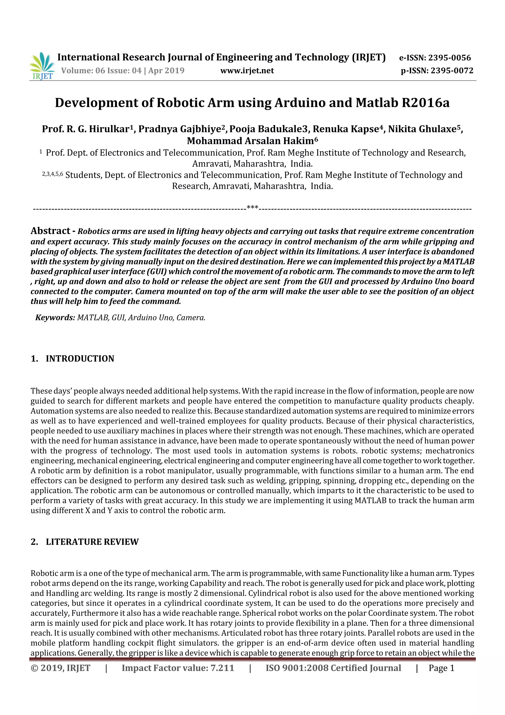
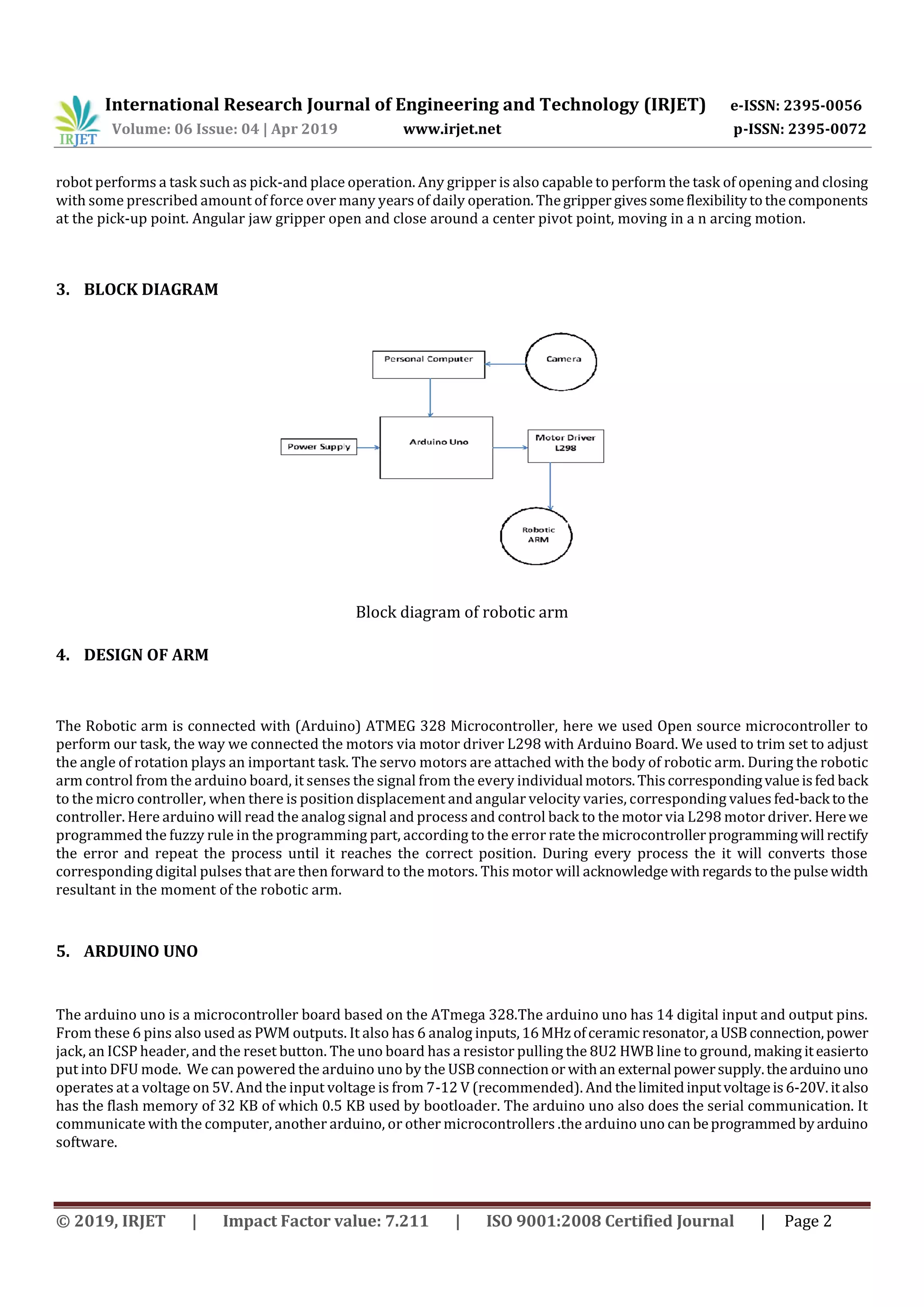
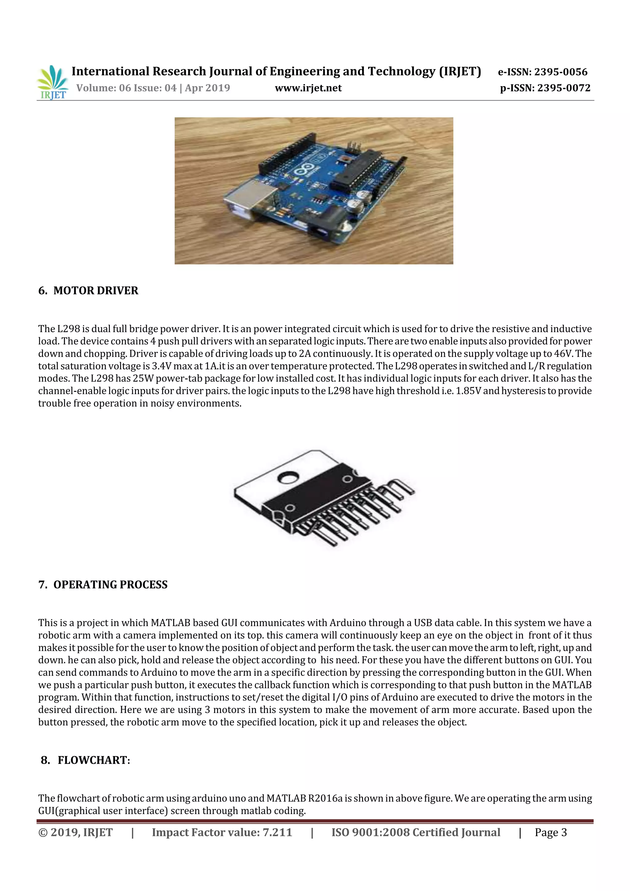
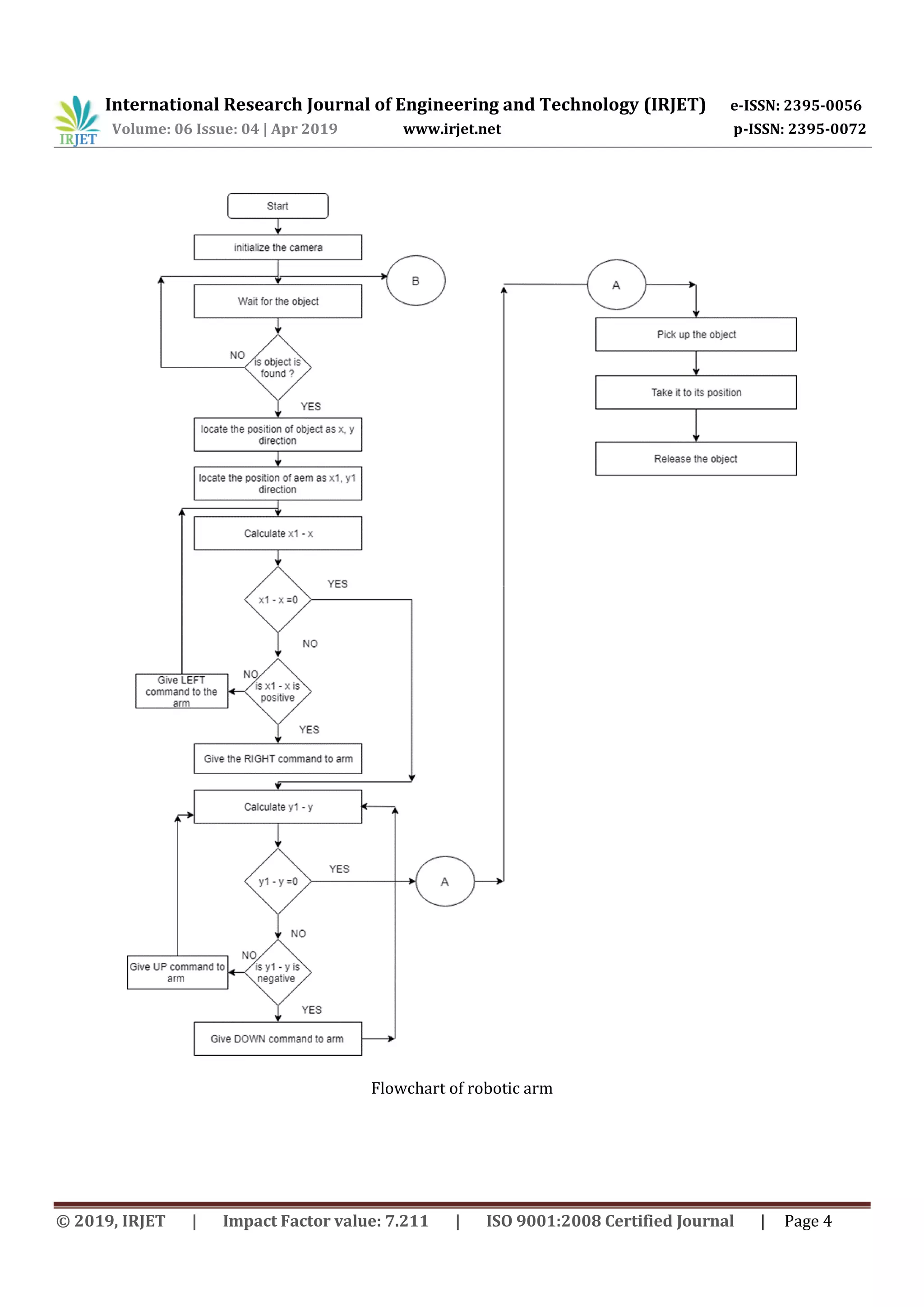
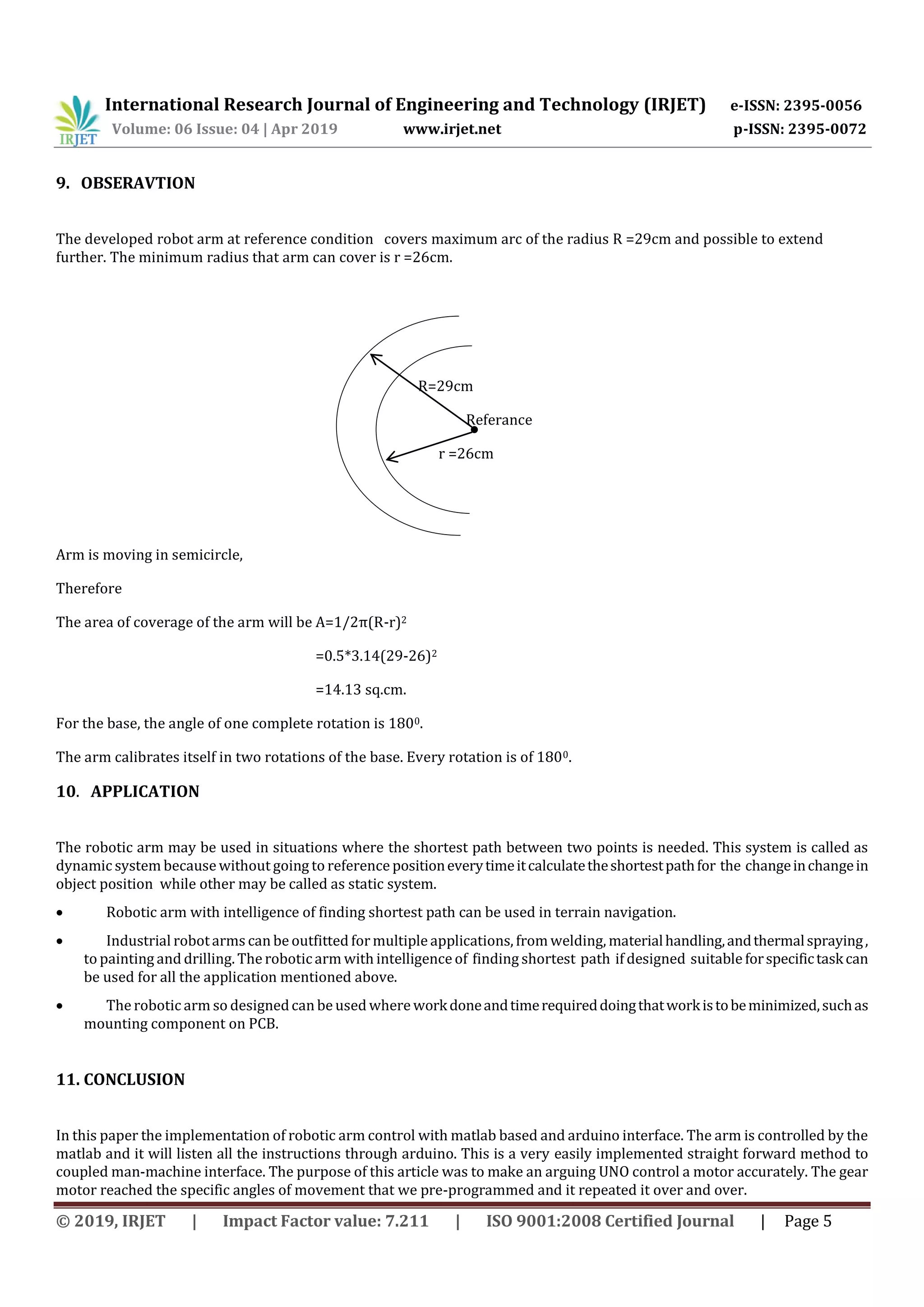


This document describes the development of a robotic arm using Arduino and MATLAB R2016a. The robotic arm is controlled through a graphical user interface in MATLAB. Commands to move the arm left, right, up, down and to grip or release objects are sent from the GUI to an Arduino Uno board connected to the computer. A camera mounted on the arm allows the user to see the position of objects and guide movements. The arm uses three motors for accurate movement and an object detection system to facilitate pick and place tasks.