Download as PDF, PPTX


![Pipeline Design (as Road Design)
𝑅=
Equivalent Radius
Equivalent Bend (Vert.)
𝐿
1
2[tan( ∆)]
2
100*ABS[ATAN({Grade In})
- ATAN({Grade Out})]
L = pipe stick length
∆ = MAX deflection
Allowable
Deflection
Max
Design
Deflection
36”
5°
2.5°
18’
412’
42”
4°
2°
18’
515’
48”
4°
2°
20’
572’
9.85%
5.625°
19.89%
Pipe
Equivalent
Length
Radius
Equivalent Bend
11.25°
41.42%
22.5°
57.73%
30°
100.00%
Pipe Size
A (Grade Change)
45°
173.20%
60°](https://image.slidesharecdn.com/autodeskuniversity2013engineeringart-140130102648-phpapp01/75/Engineering-Art-at-Autodesk-University-2013-30-2048.jpg)


![Pipeline Design (as Road Design)
𝑅=
Equivalent Radius
Equivalent Bend (Vert.)
𝐿
1
2[tan( ∆)]
2
100*ABS[ATAN({Grade In})
- ATAN({Grade Out})]
L = pipe stick length
∆ = MAX deflection
Allowable
Deflection
Max
Design
Deflection
36”
5°
2.5°
18’
412’
42”
4°
2°
18’
515’
48”
4°
2°
20’
572’
9.85%
5.625°
19.89%
Pipe
Equivalent
Length
Radius
Equivalent Bend
11.25°
41.42%
22.5°
57.73%
30°
100.00%
Pipe Size
A (Grade Change)
45°
173.20%
60°](https://crownmelresort.com/image.slidesharecdn.com/autodeskuniversity2013engineeringart-140130102648-phpapp01/75/Engineering-Art-at-Autodesk-University-2013-30-2048.jpg)


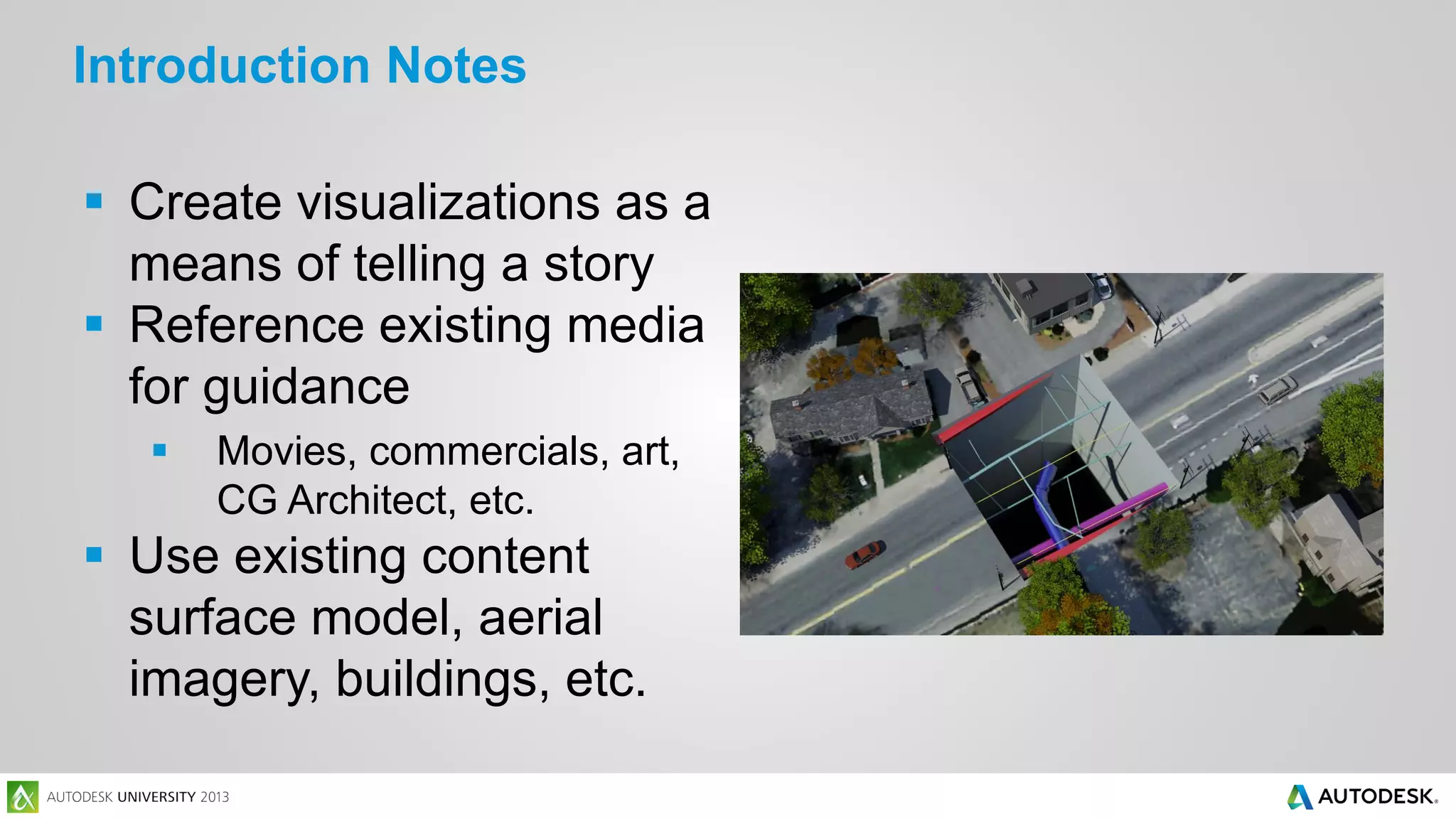
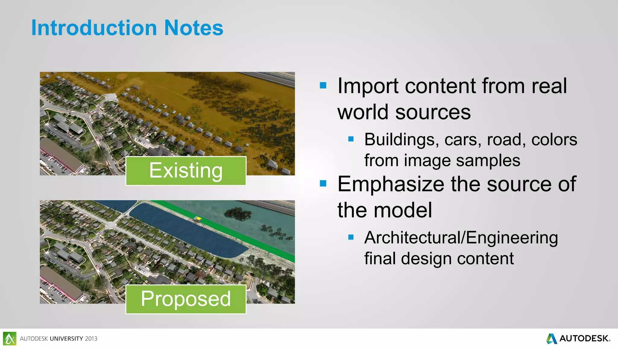
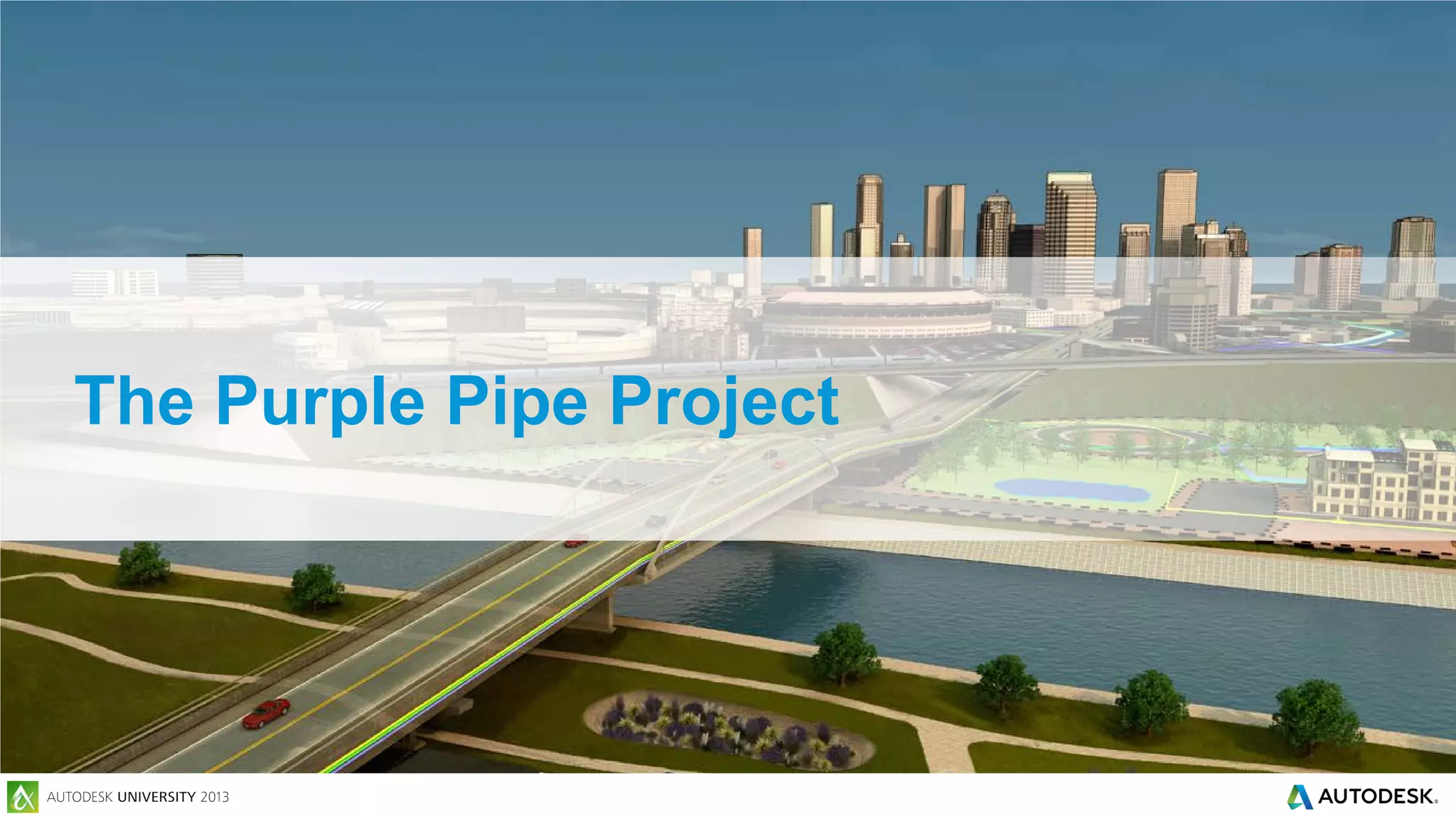
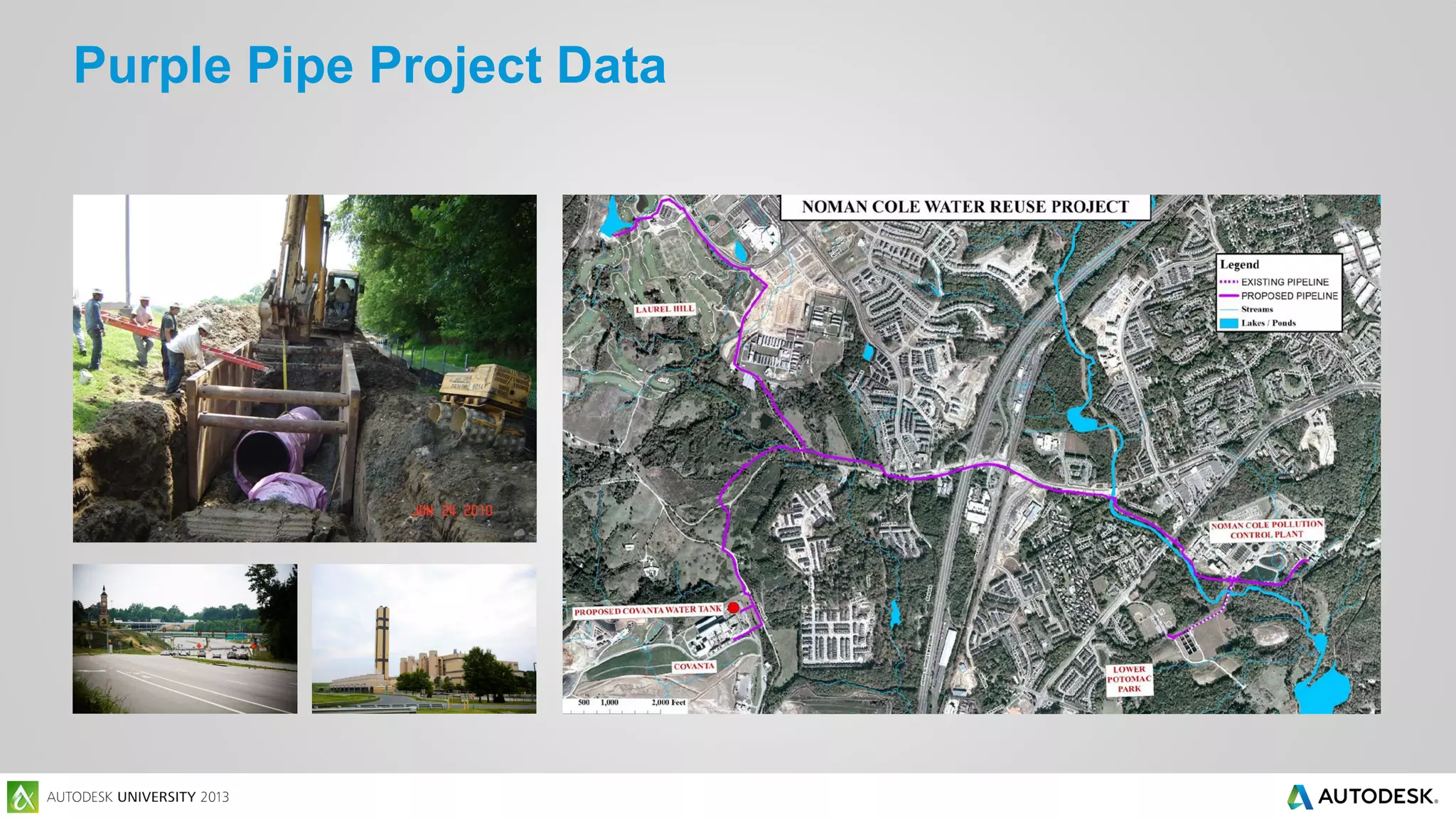
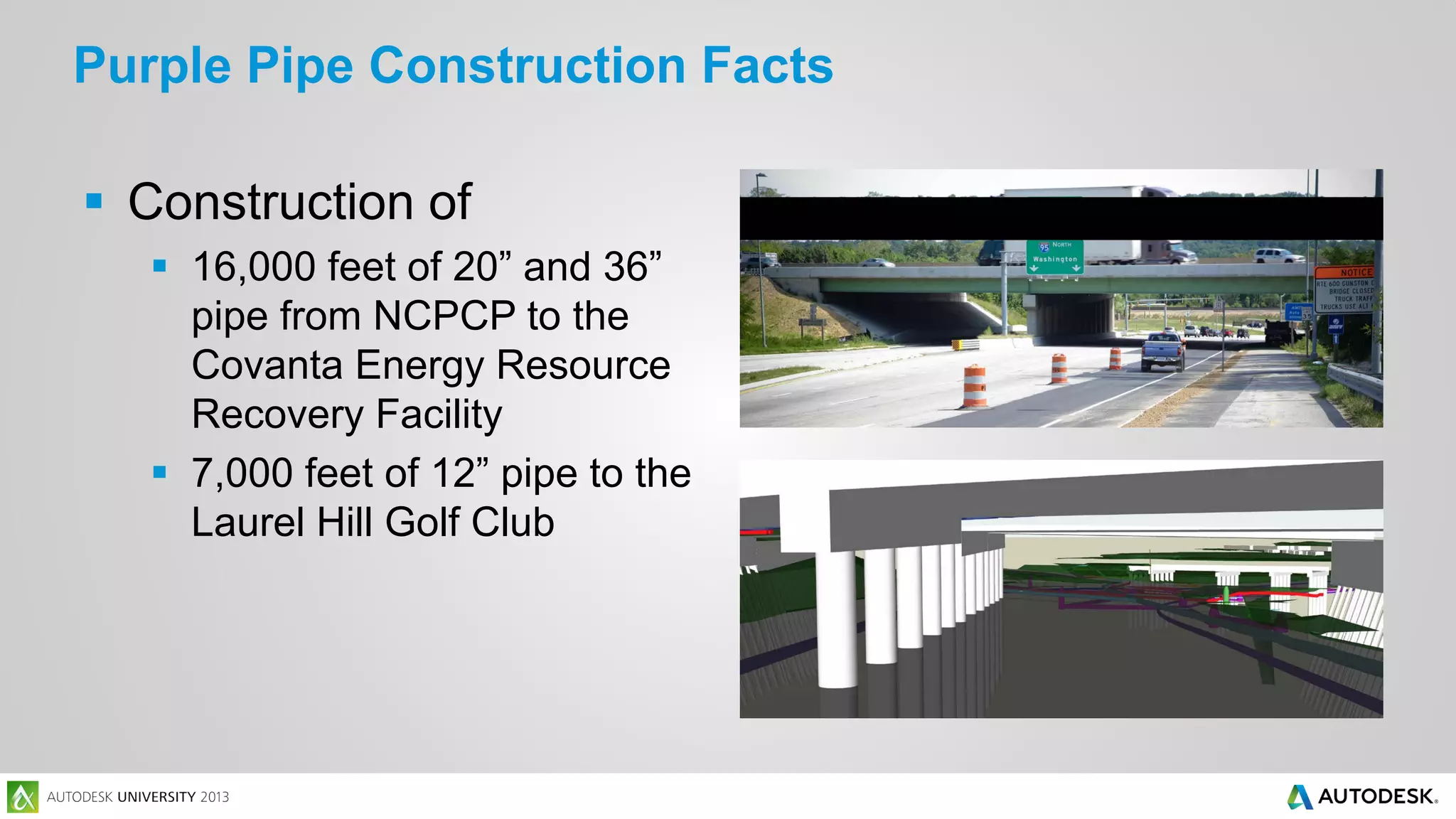
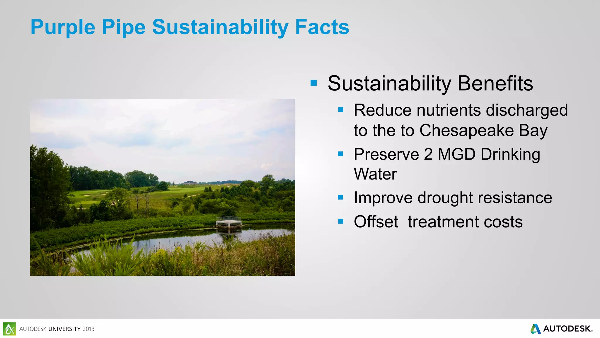
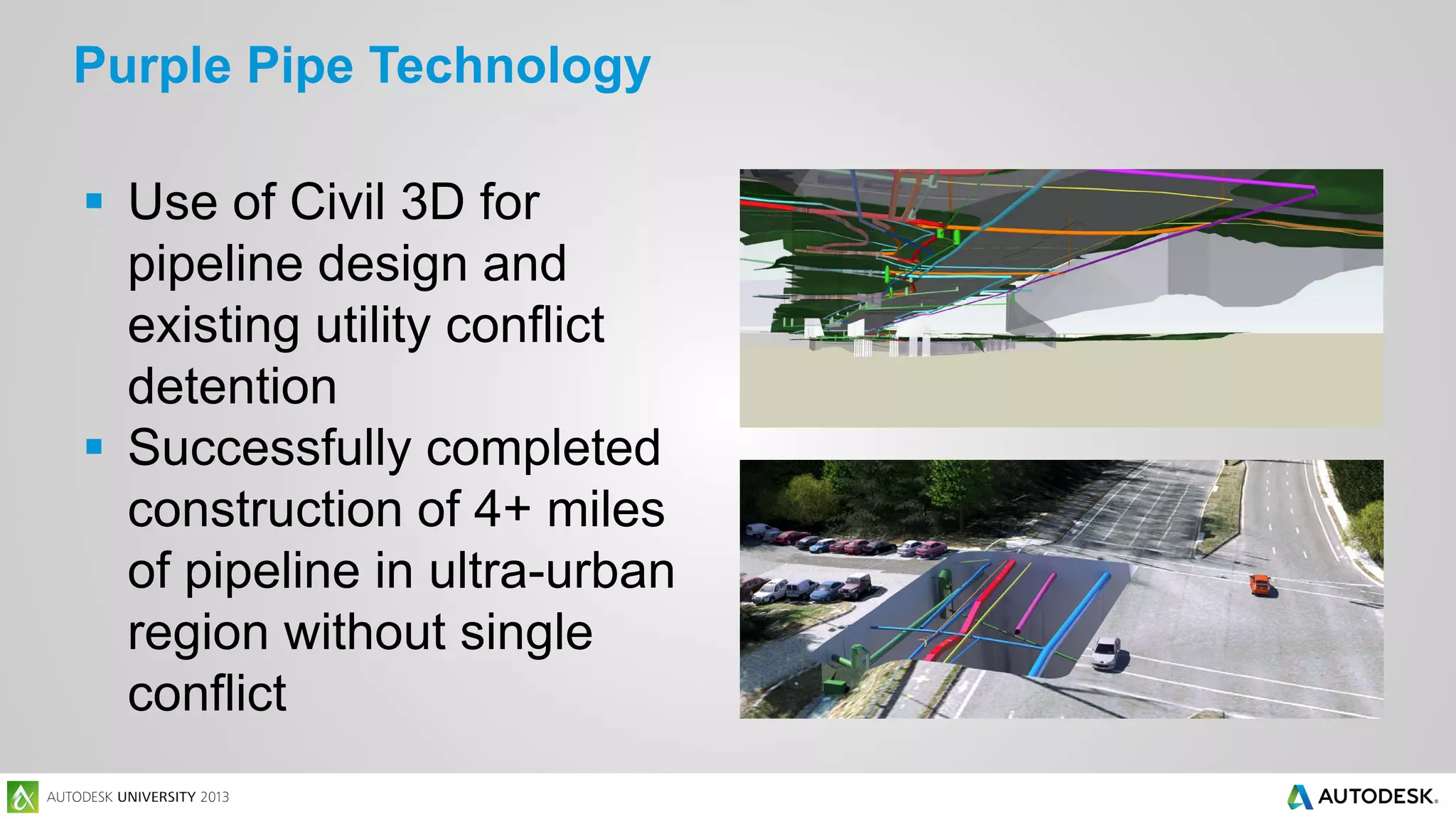
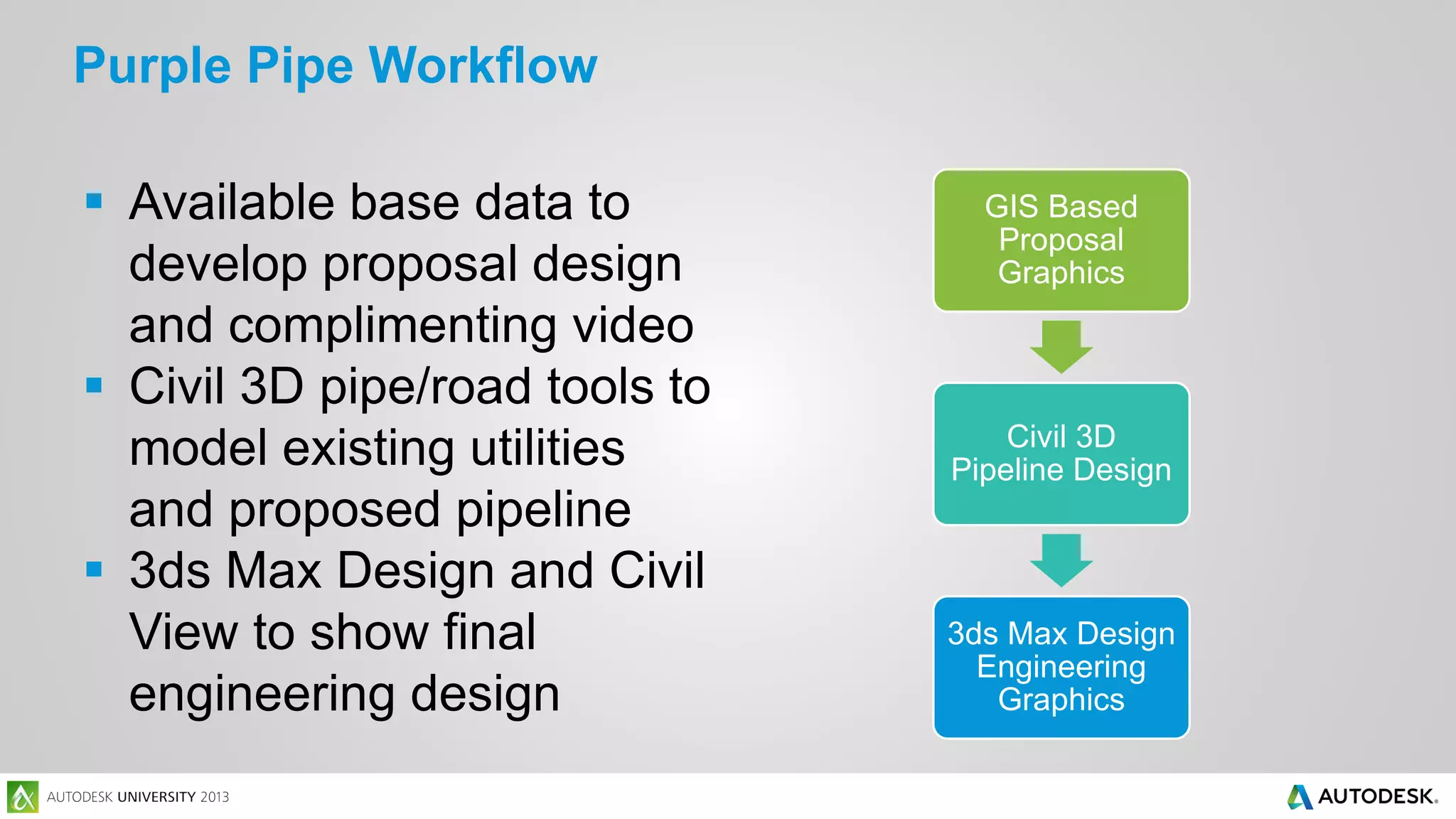
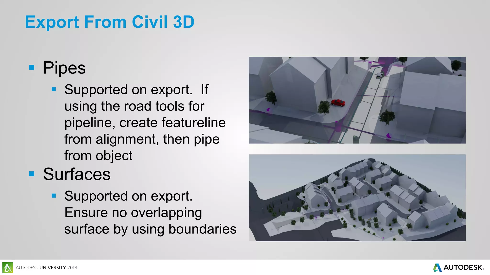
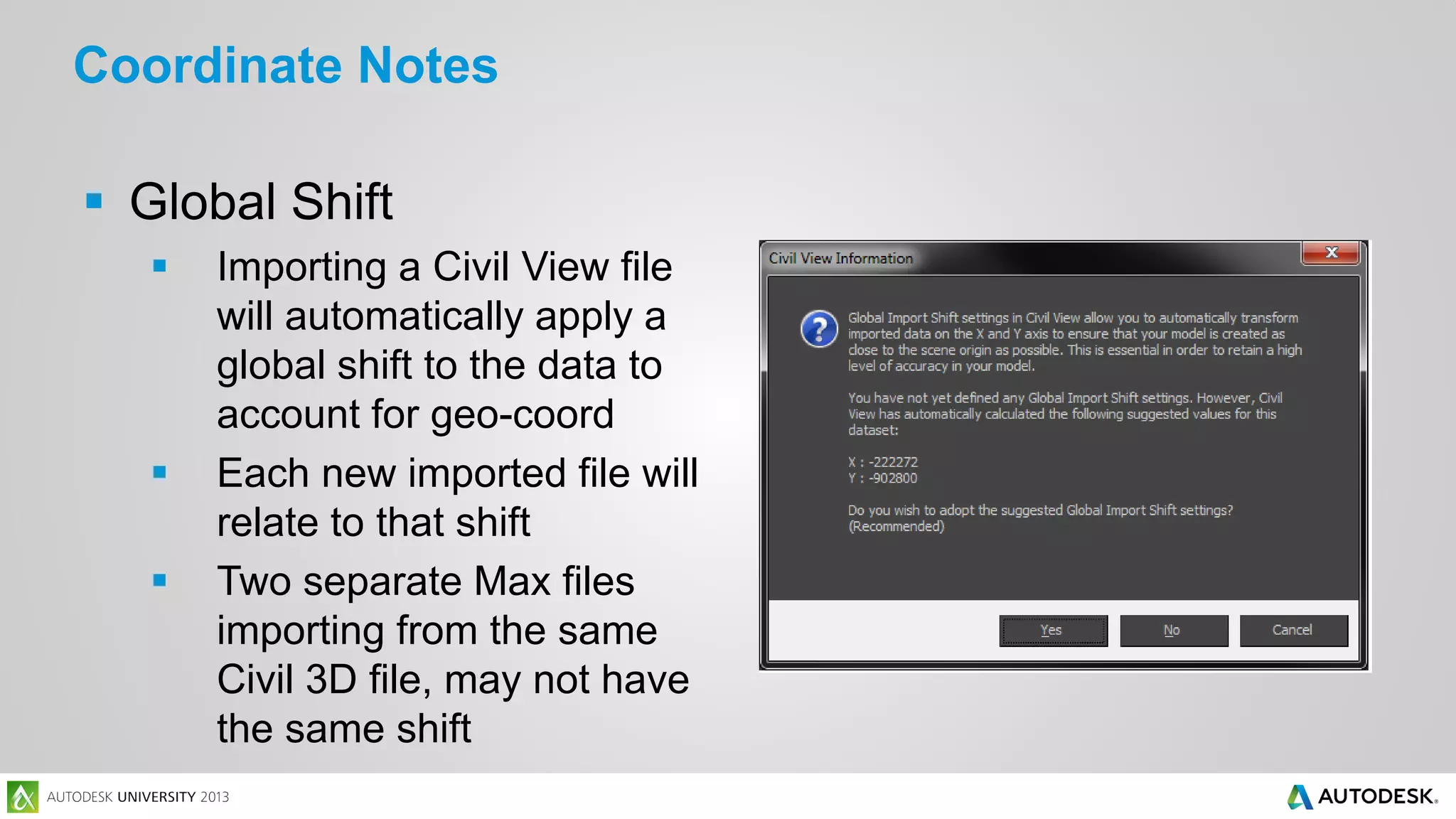
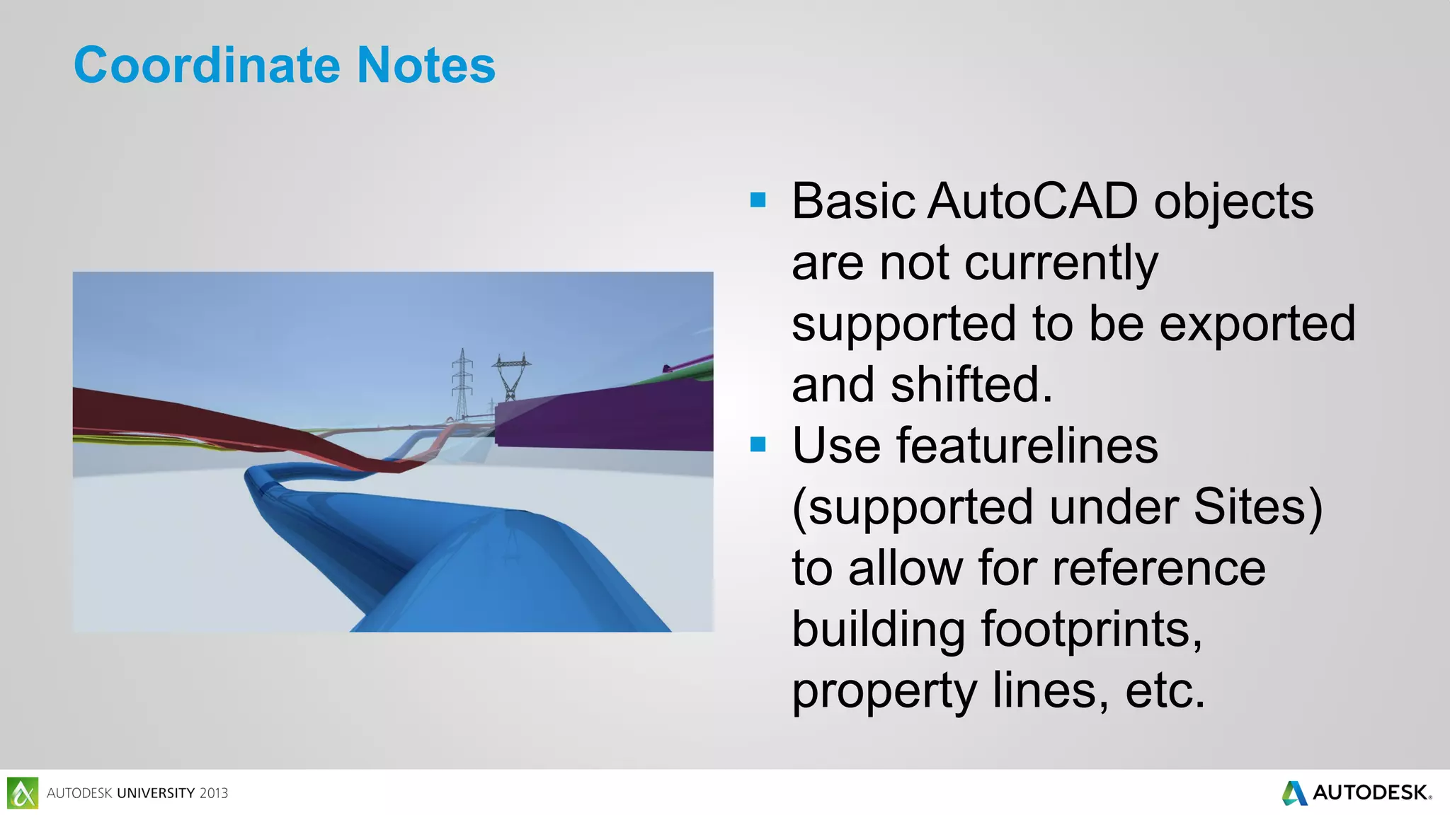
The document outlines Dewberry's services in engineering and design, emphasizing the competitive advantage of technical visualizations for marketing proposals. It details a class focused on using Civil 3D, Infraworks, and 3ds Max Design for effective visualization and modeling in civil engineering projects. The Purple Pipe Project demonstrates practical applications of these tools, showcasing sustainability benefits and innovative design workflows.


![Support, Monitoring, Continuous Improvement & Scaling Agentic Automation [3/3]](https://cdn.slidesharecdn.com/ss_thumbnails/agenticcommunityseries-day3-cfd-251120170304-ddef8112-thumbnail.jpg?width=640&height=640&fit=bounds)


