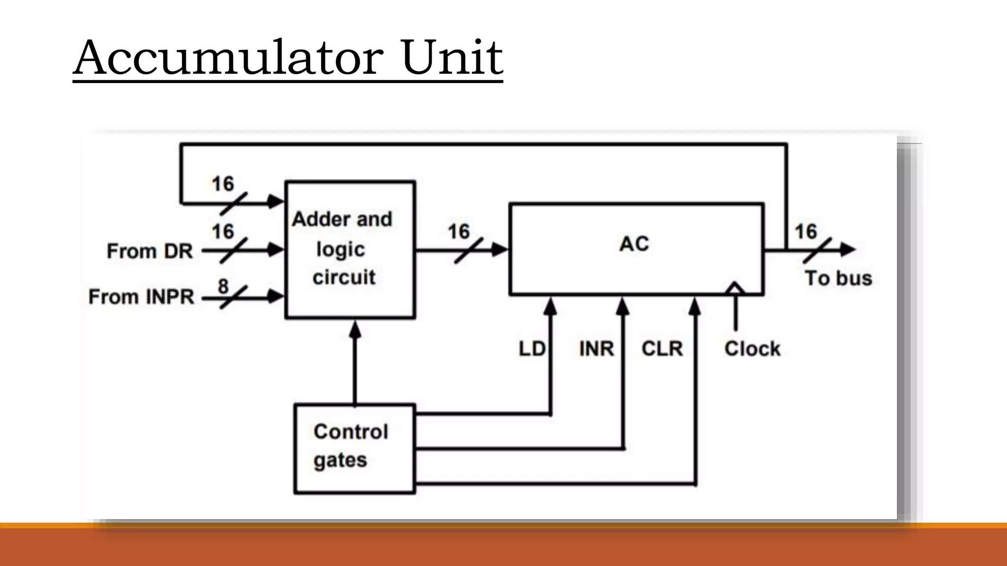
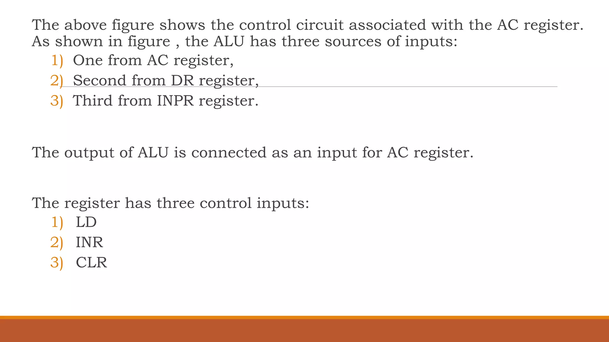
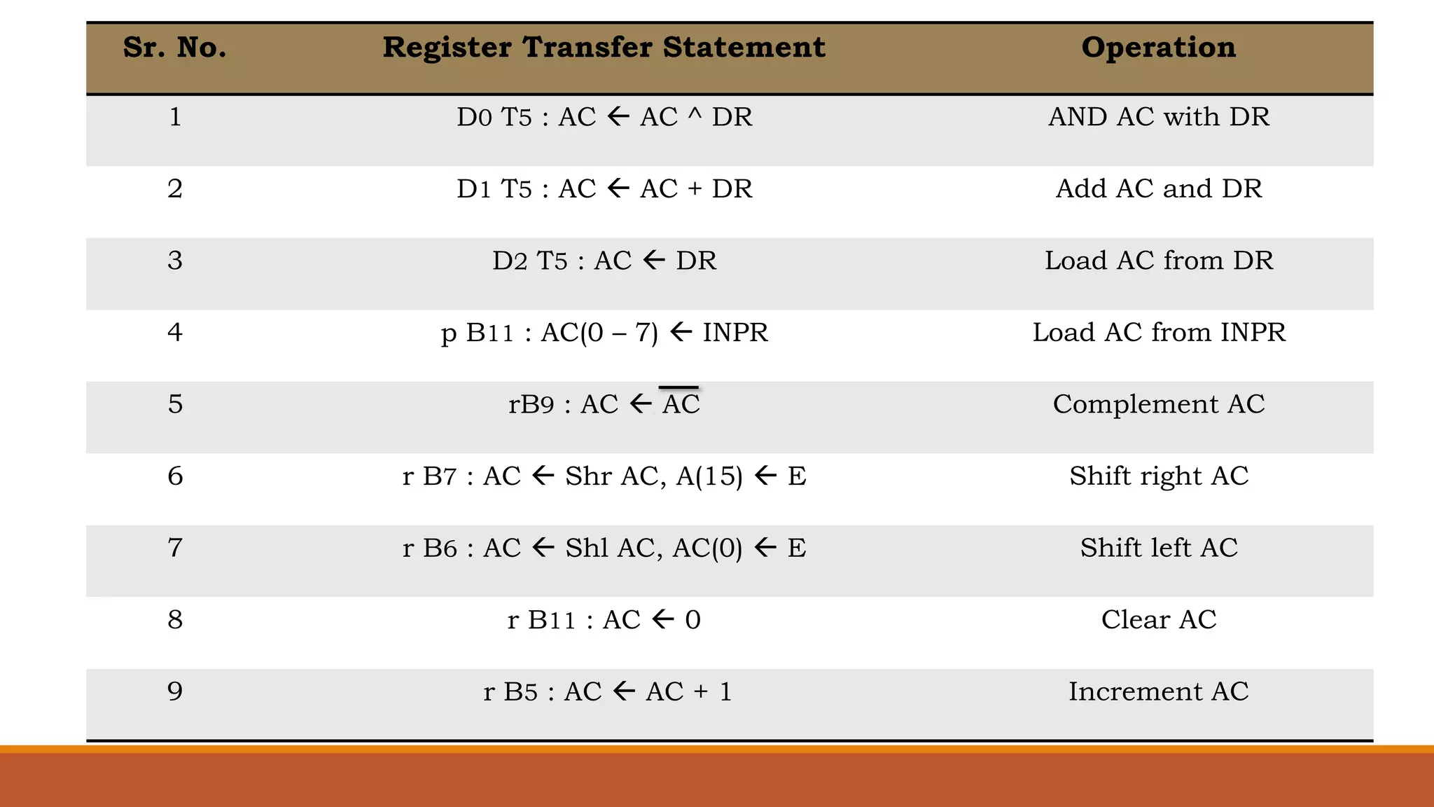
Name: Koshti Harshad
Branch: CE
Subject: Computer Organization
Subject Code: 2140707
Topic: Design of Accumulator unit
Accumulator Unit
The above figure shows the control circuit associated with the AC register.
As shown in figure , the ALU has three sources of inputs:
1) One from AC register,
2) Second from DR register,
3) Third from INPR register.
The output of ALU is connected as an input for AC register.
The register has three control inputs:
1) LD
2) INR
3) CLR
Sr. No. Register Transfer Statement Operation
1 D0 T5 : AC  AC ^ DR AND AC with DR
2 D1 T5 : AC  AC + DR Add AC and DR
3 D2 T5 : AC  DR Load AC from DR
4 p B11 : AC(0 – 7)  INPR Load AC from INPR
5 rB9 : AC  AC Complement AC
6 r B7 : AC  Shr AC, A(15)  E Shift right AC
7 r B6 : AC  Shl AC, AC(0)  E Shift left AC
8 r B11 : AC  0 Clear AC
9 r B5 : AC  AC + 1 Increment AC
Thank
You

Design of Accumulator Unit

  • 1.
    Name: Koshti Harshad Branch:CE Subject: Computer Organization Subject Code: 2140707 Topic: Design of Accumulator unit
  • 2.
  • 3.
    The above figureshows the control circuit associated with the AC register. As shown in figure , the ALU has three sources of inputs: 1) One from AC register, 2) Second from DR register, 3) Third from INPR register. The output of ALU is connected as an input for AC register. The register has three control inputs: 1) LD 2) INR 3) CLR
  • 4.
    Sr. No. RegisterTransfer Statement Operation 1 D0 T5 : AC  AC ^ DR AND AC with DR 2 D1 T5 : AC  AC + DR Add AC and DR 3 D2 T5 : AC  DR Load AC from DR 4 p B11 : AC(0 – 7)  INPR Load AC from INPR 5 rB9 : AC  AC Complement AC 6 r B7 : AC  Shr AC, A(15)  E Shift right AC 7 r B6 : AC  Shl AC, AC(0)  E Shift left AC 8 r B11 : AC  0 Clear AC 9 r B5 : AC  AC + 1 Increment AC
  • 5.