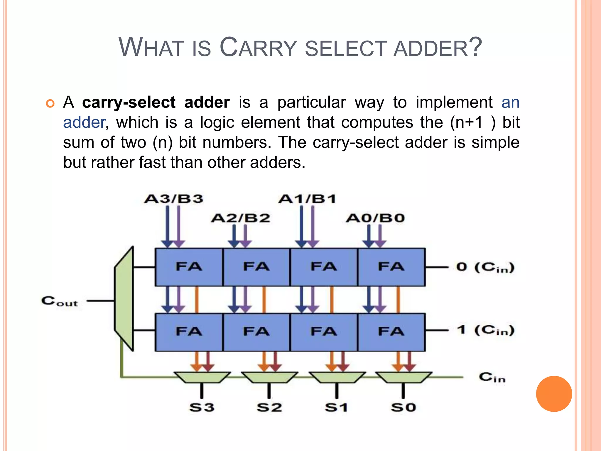
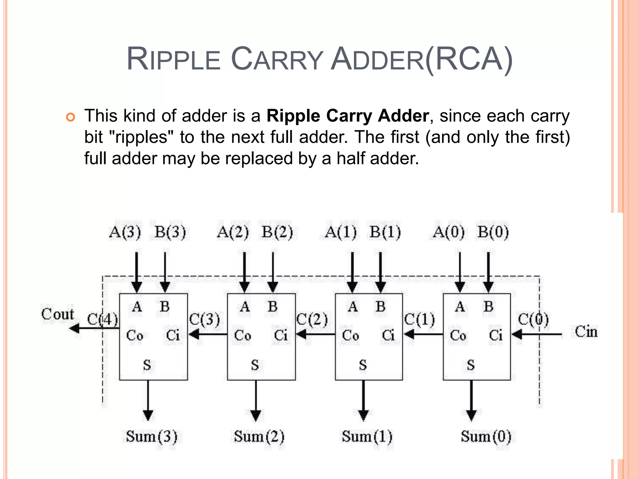
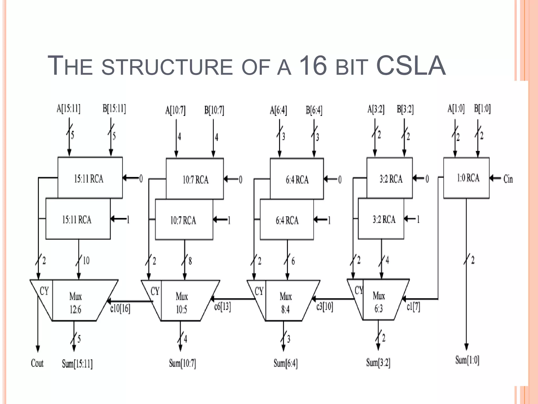
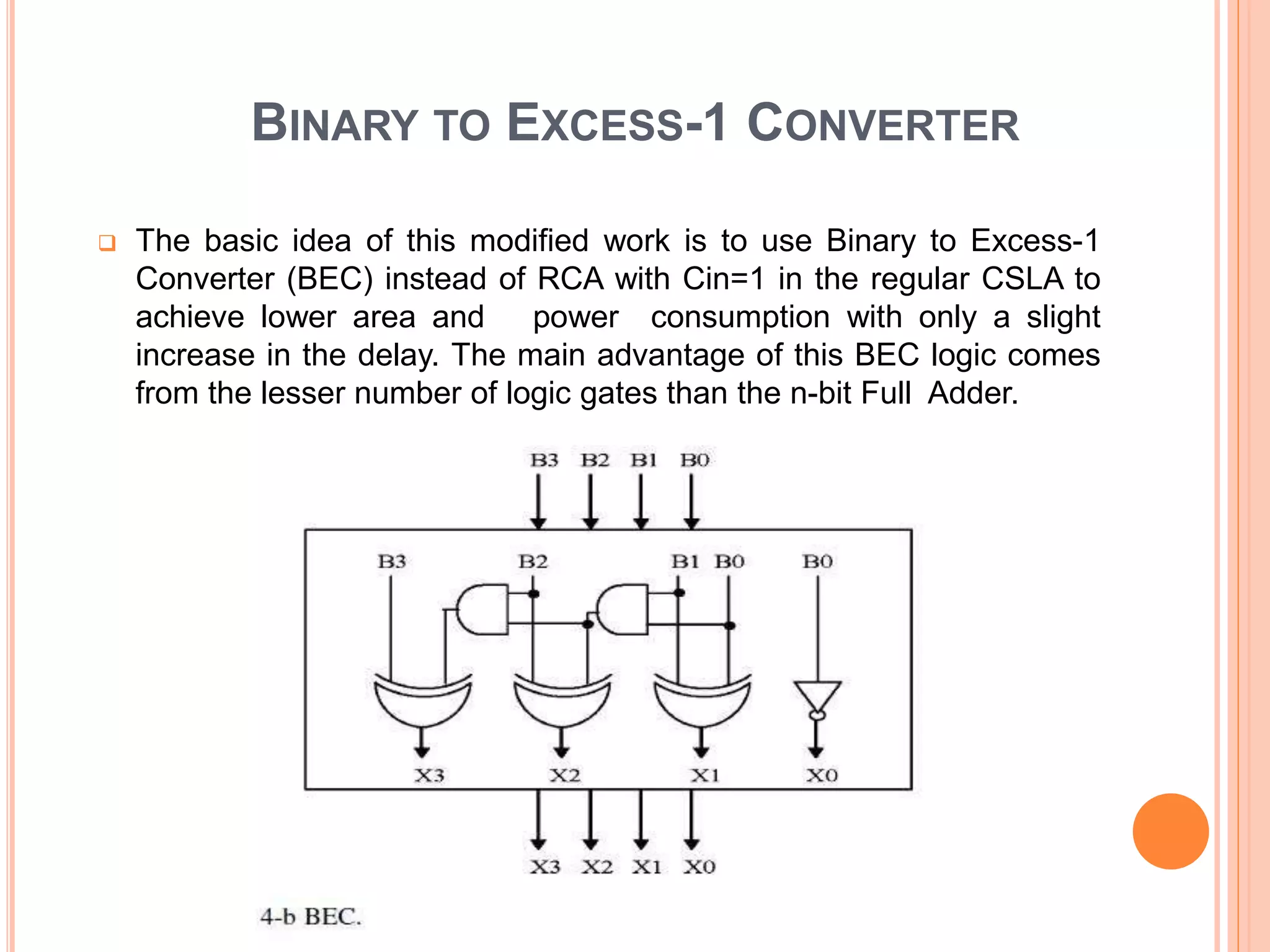
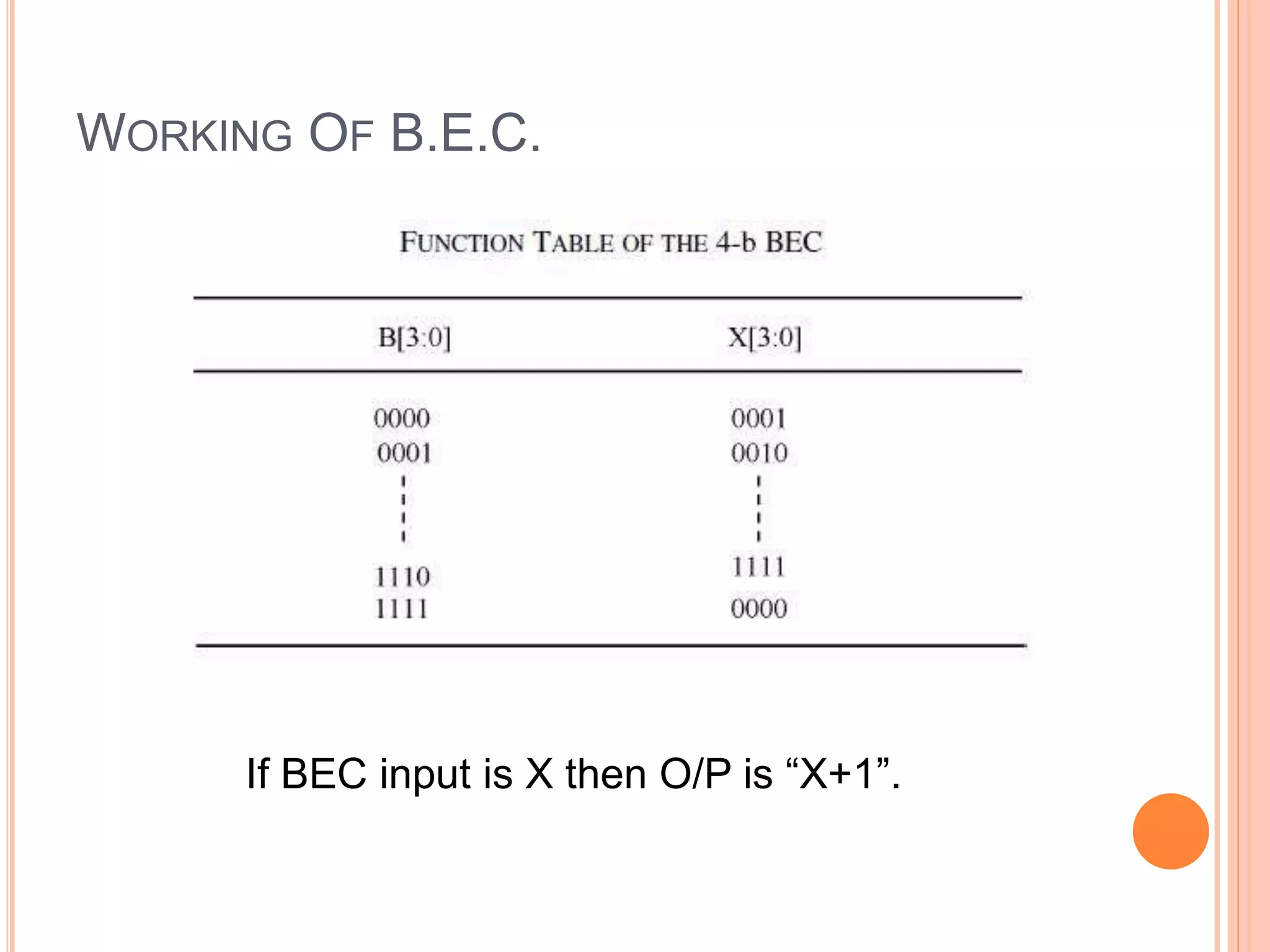
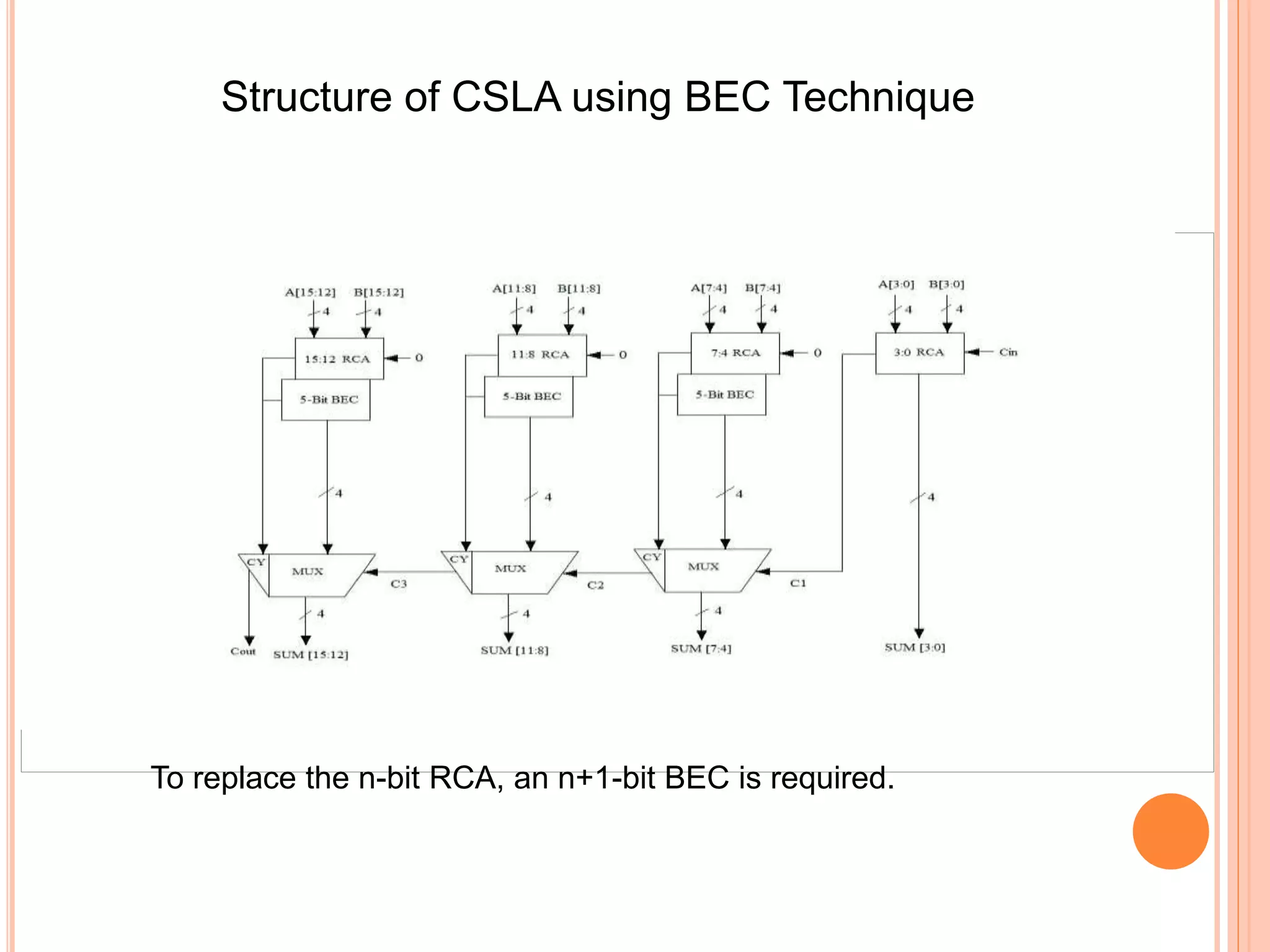
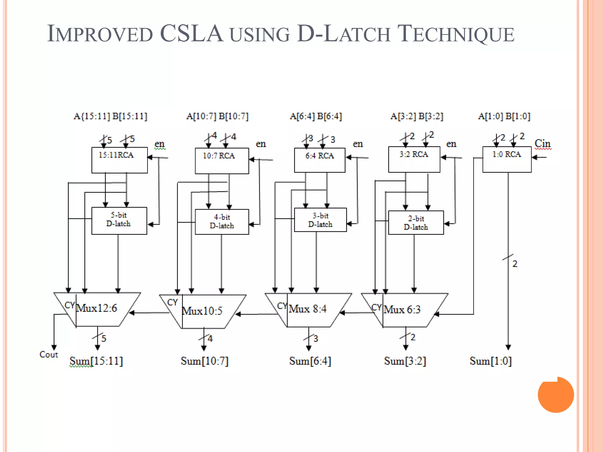
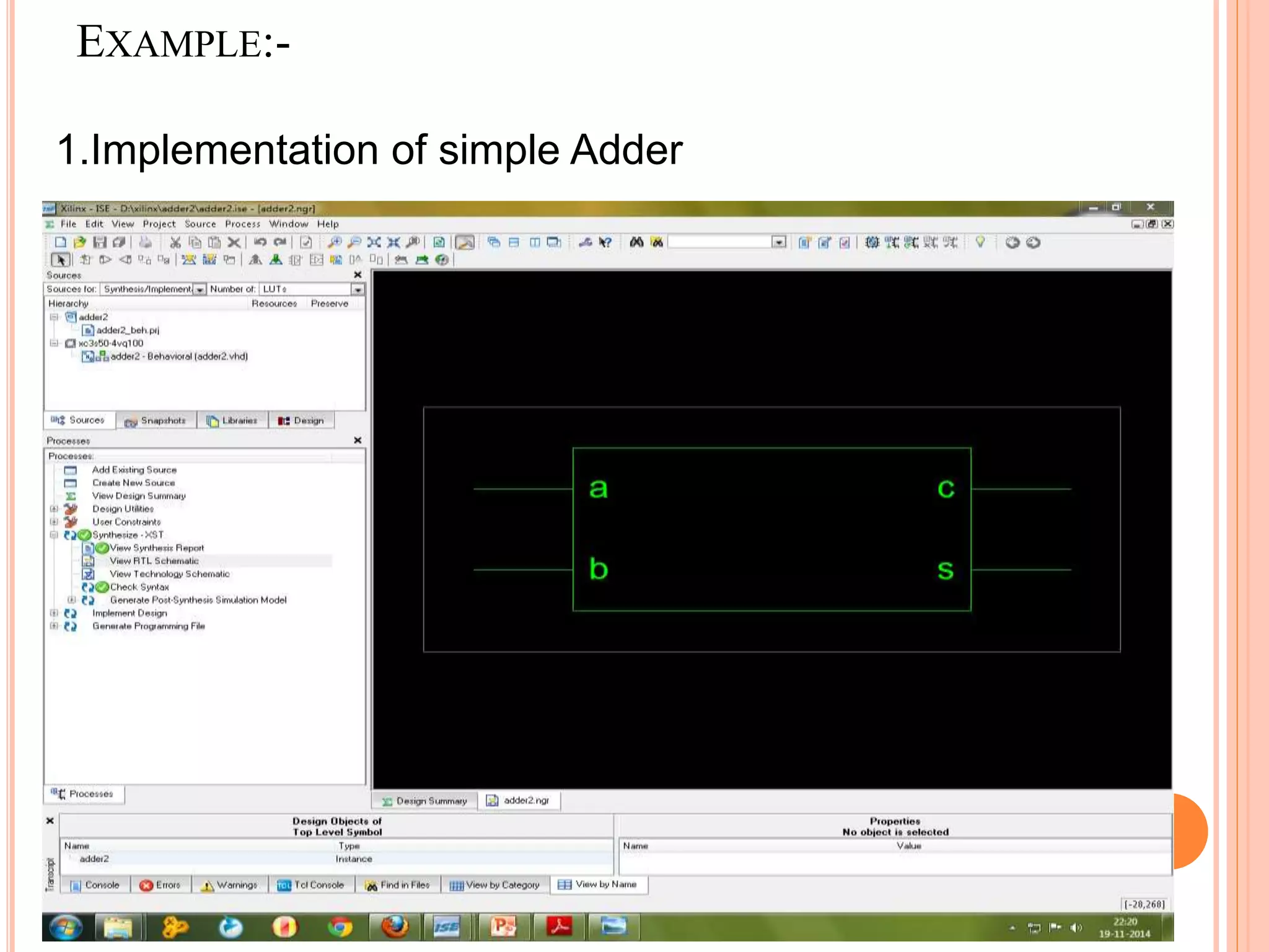
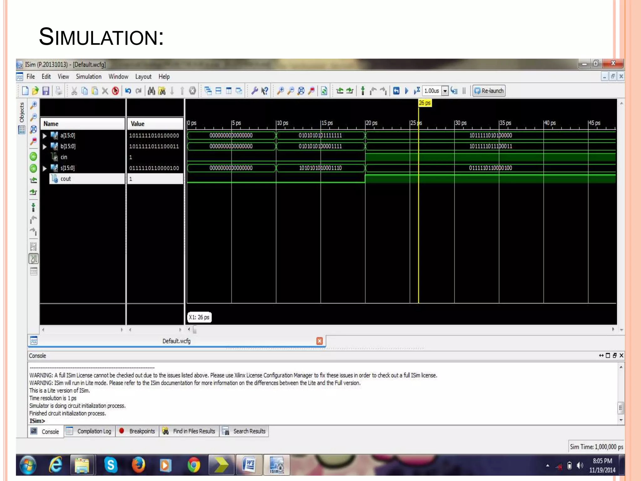
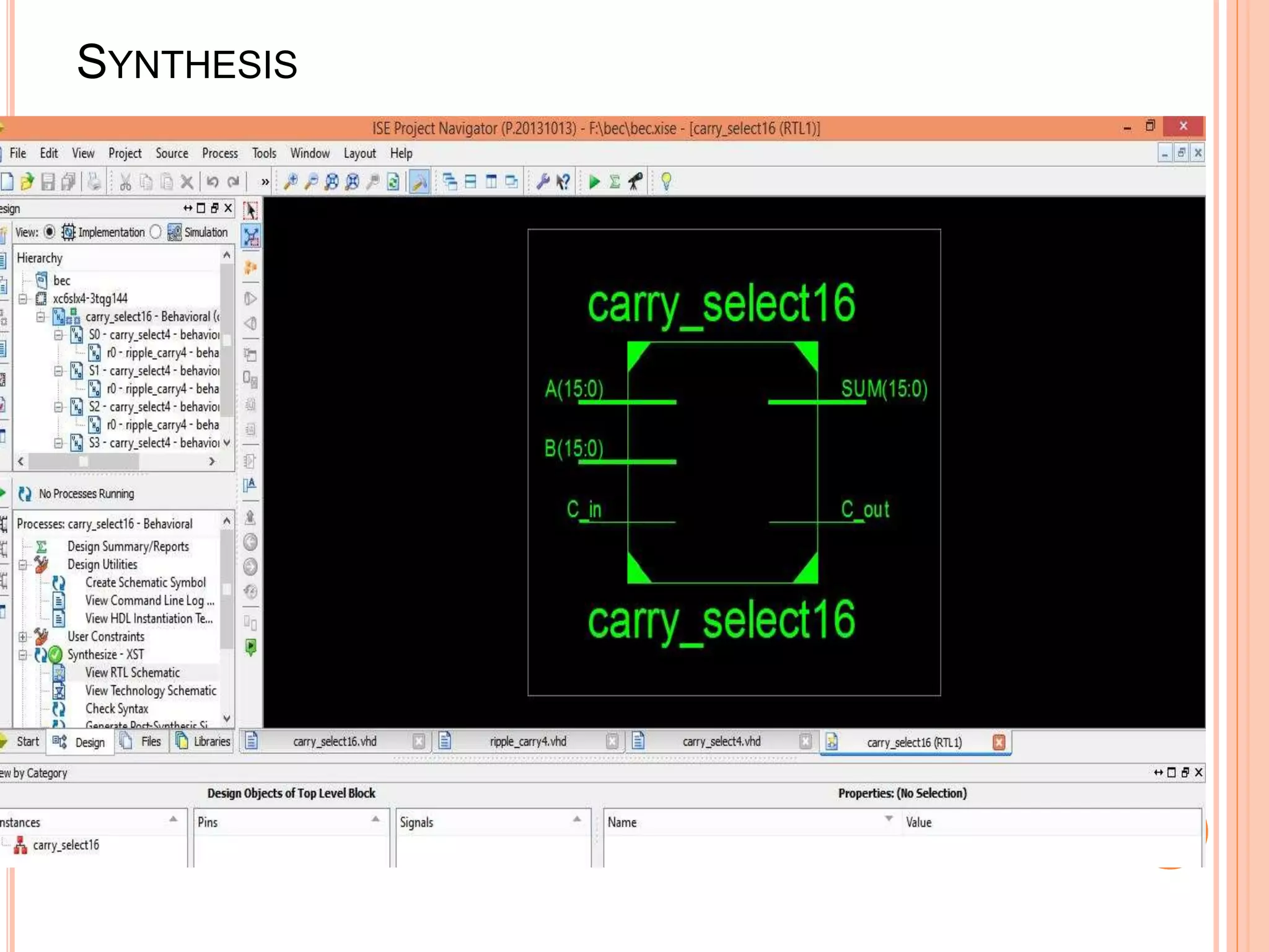
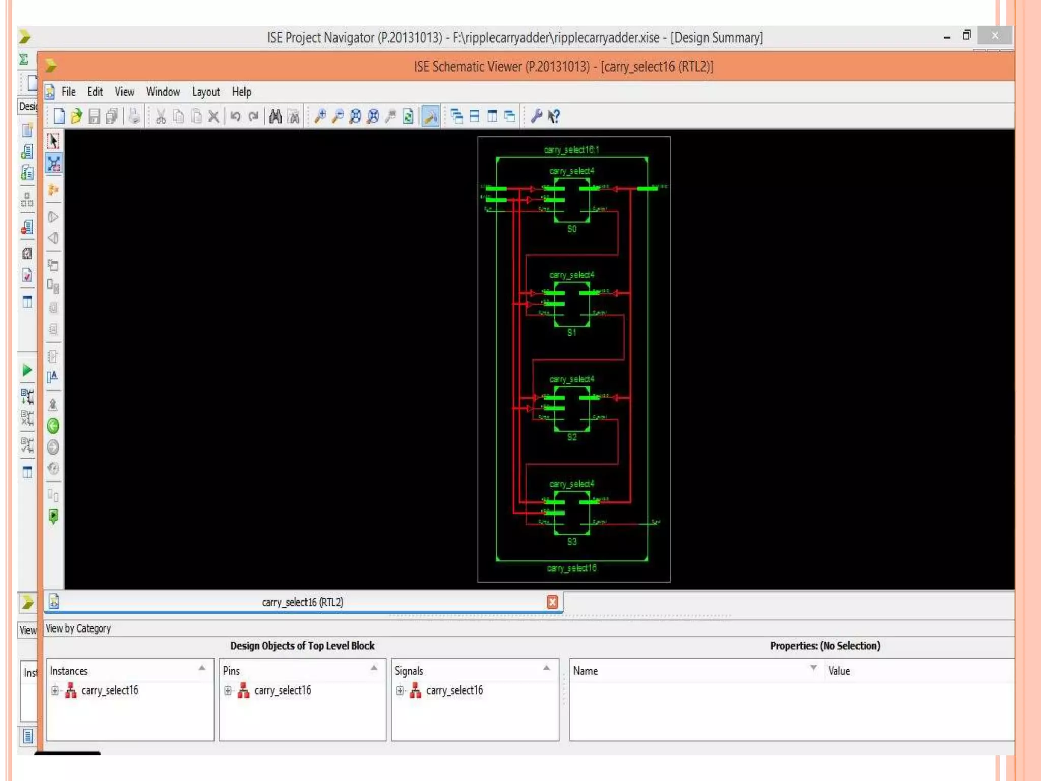
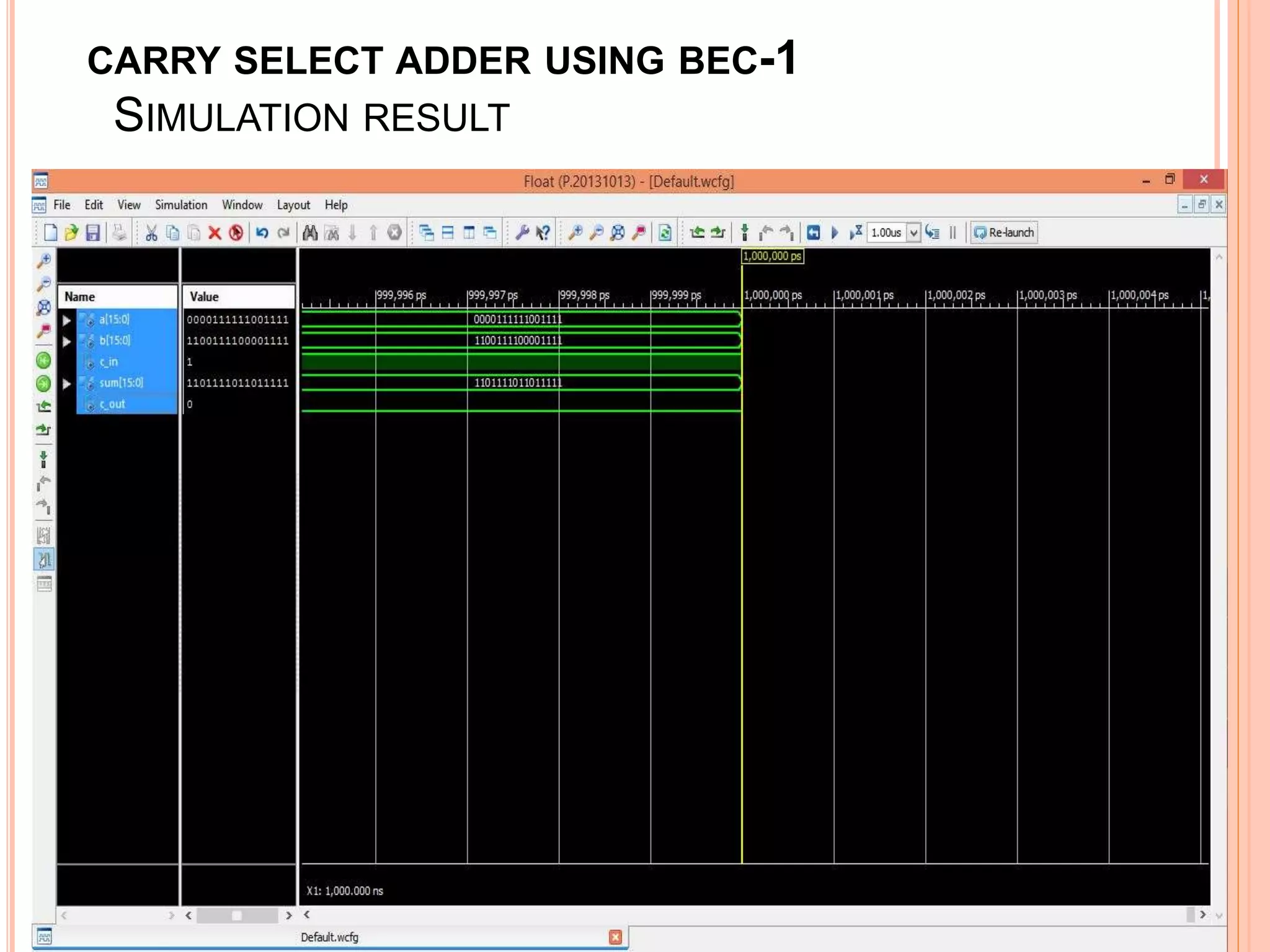
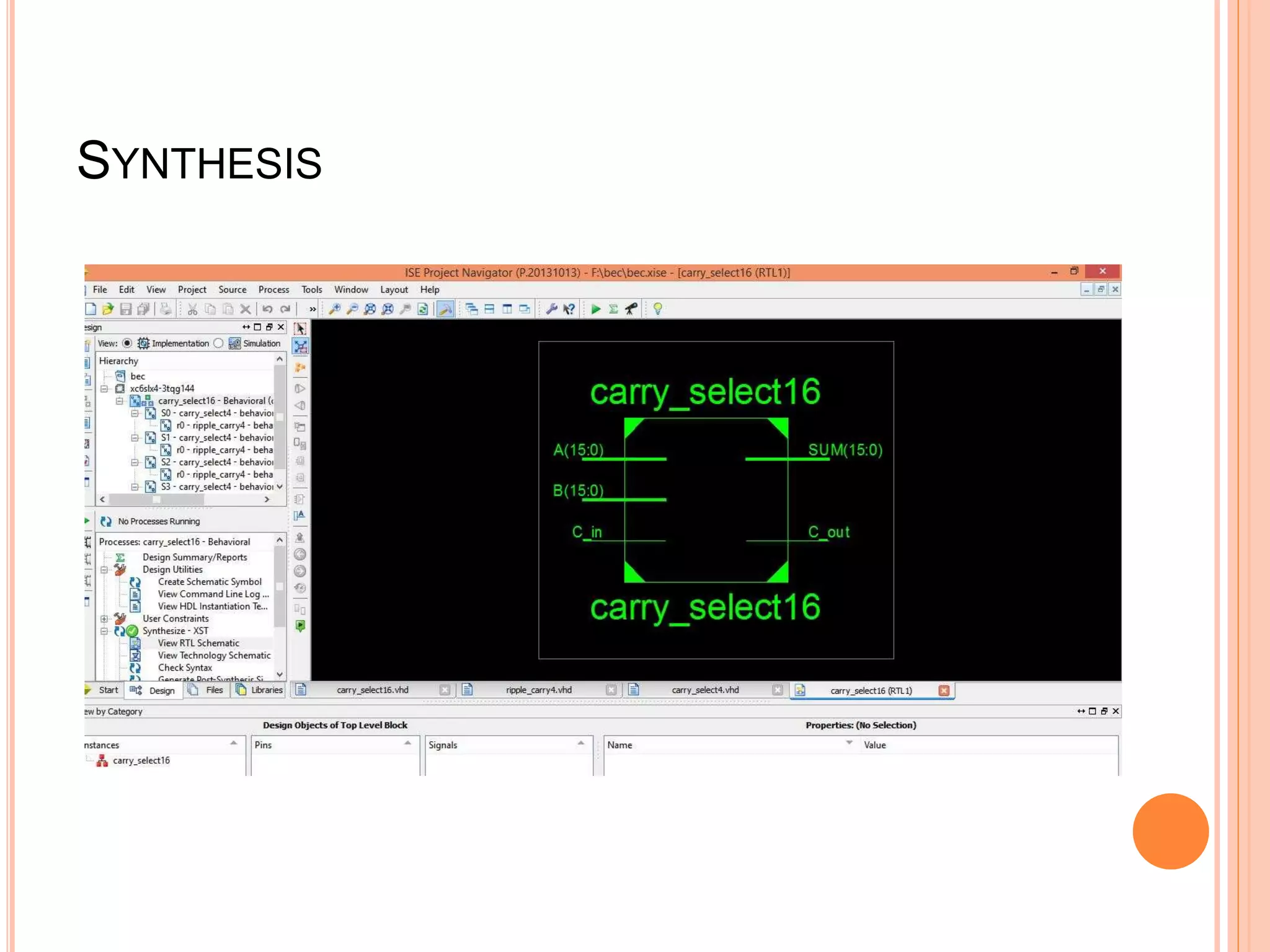
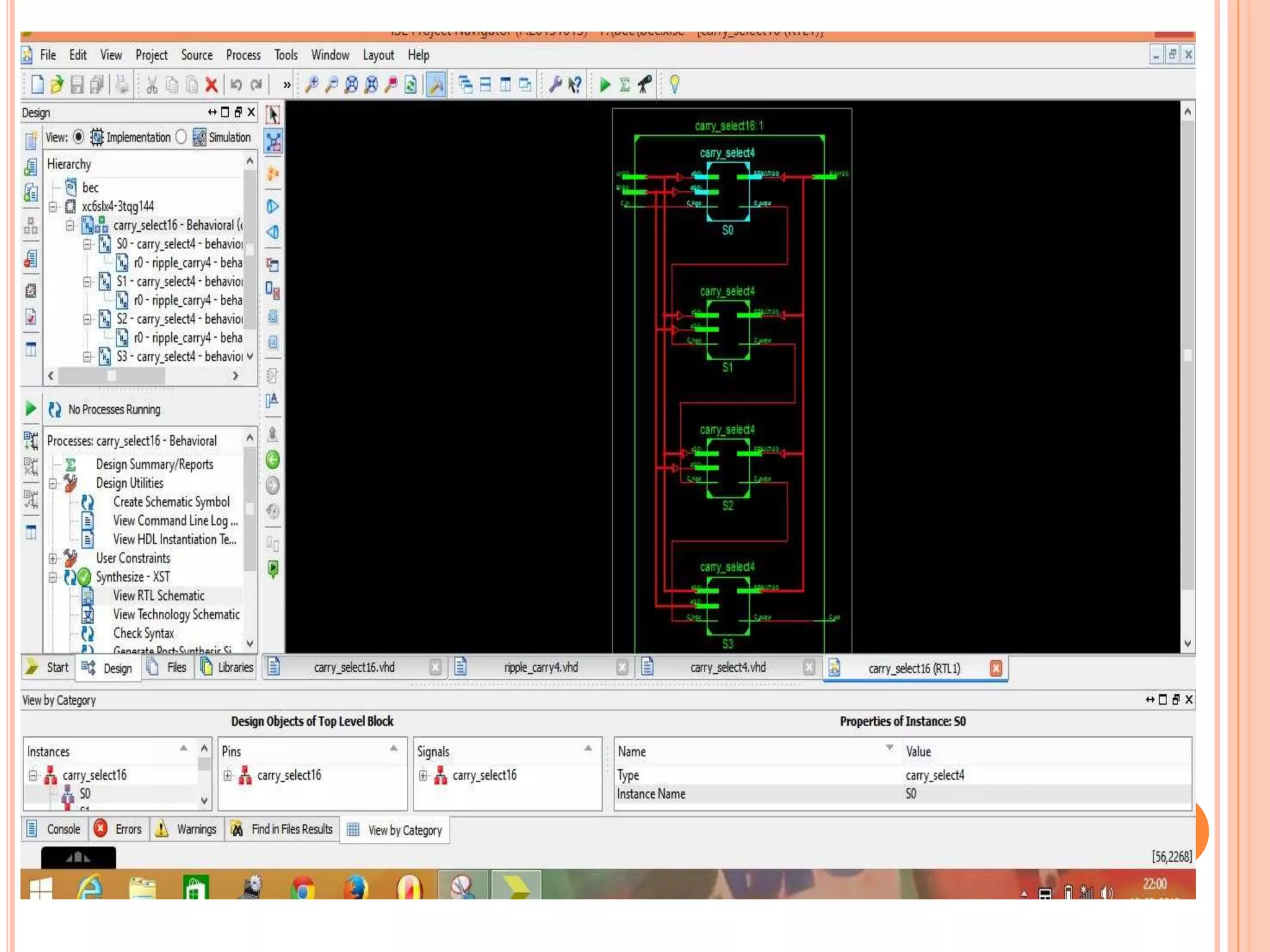
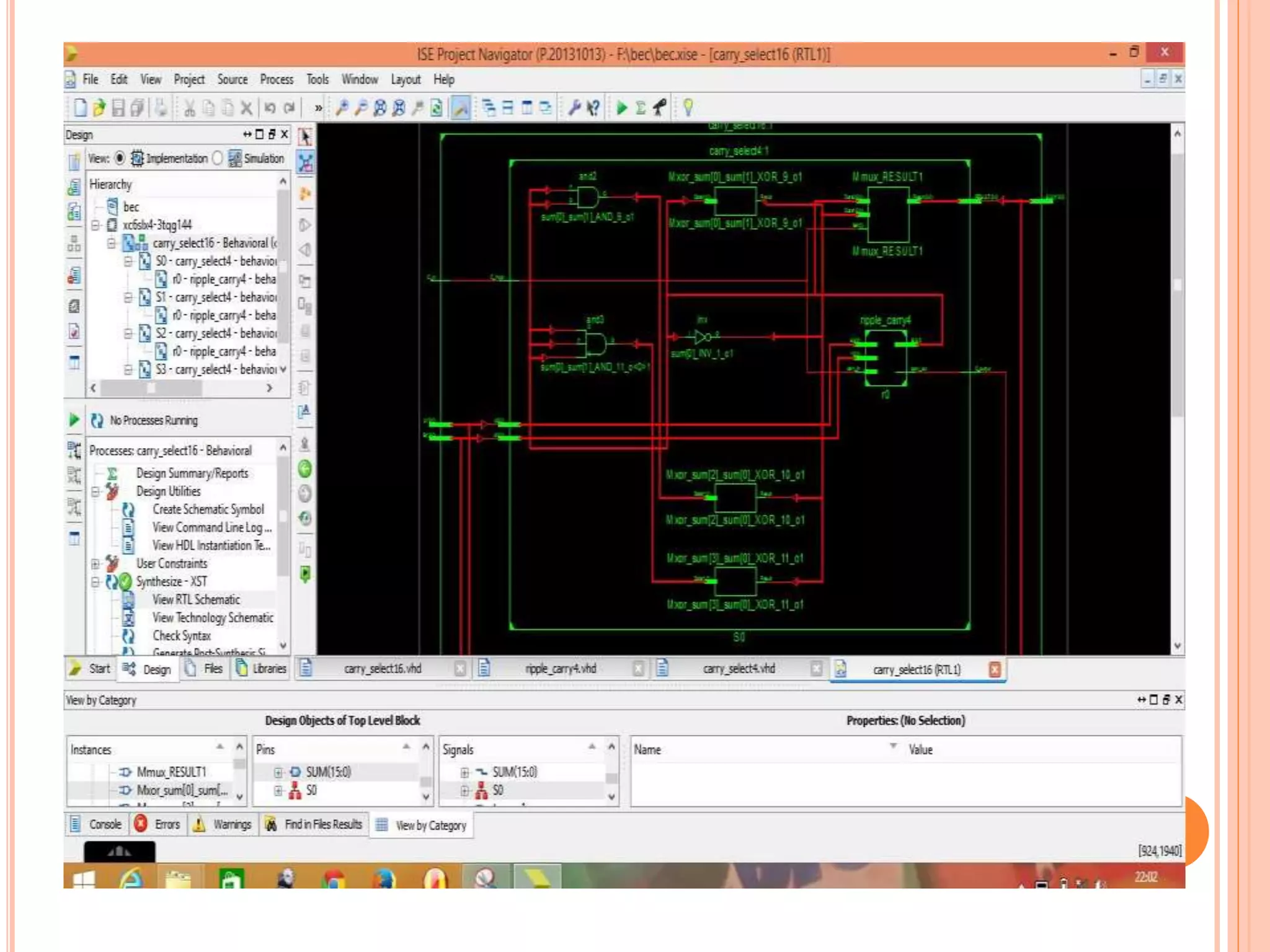
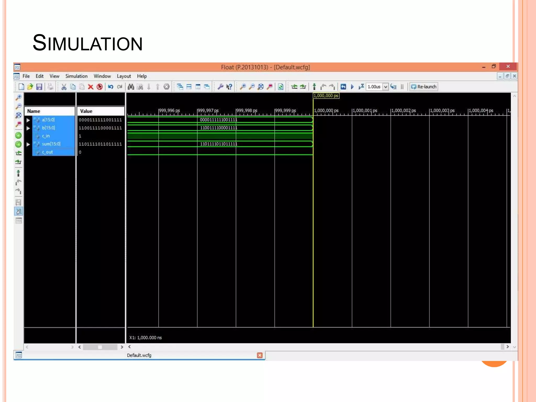
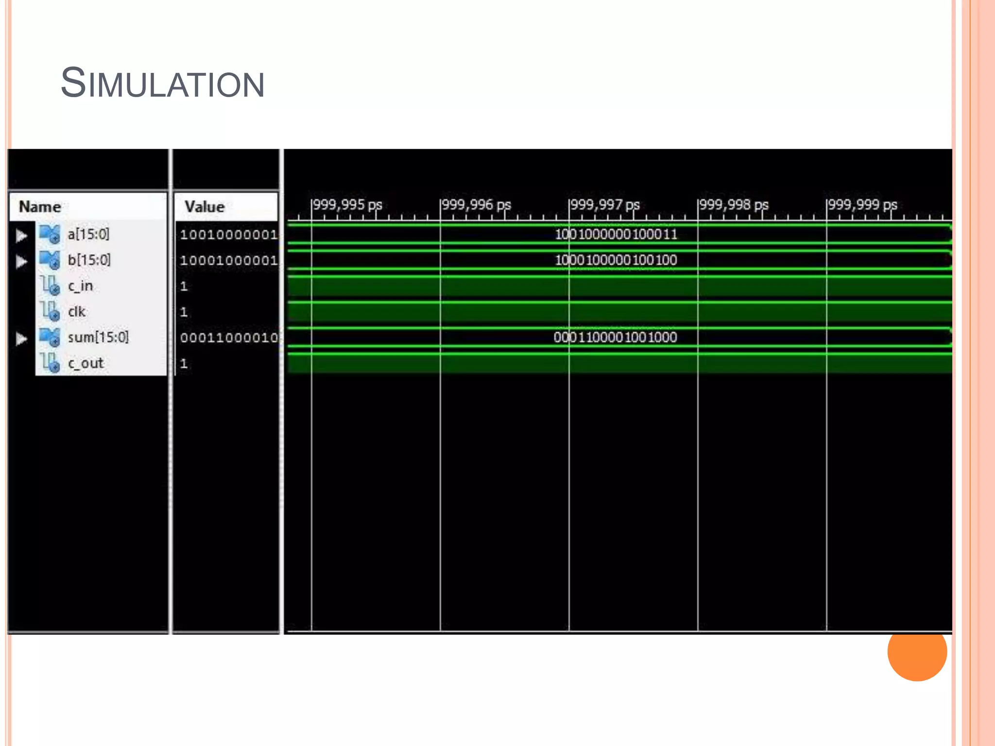
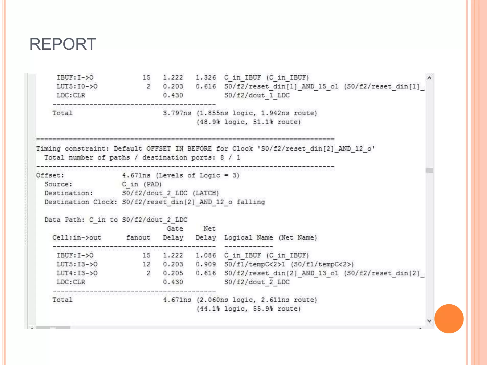
DESIGN AND IMPLEMENTATION OF HIGH
SPEED CARRY SELECT ADDER
Submitted by:-
Shivam Babele
Shikha Gupta
Shubham Singh
Shovit Tyagi
Guided by:-
Mrs. Shiva Agrawal
Assistant Professor
EC Department
CONTENTS
1.Introduction
2.What is Carry Select adder?
3. 16 bit regular Carry select adder
4. Ripple Carry adder(RCA)
5.Binary to Excess-1 converter(B.E.C.)
6.Limitations
7. D- Latch
8. Tool
9.References
INTRODUCTION
 In VLSI system design the area and power reduction in data path logic
systems are the main area of research . High speed addition and
multiplication has always been a fundamental requirement of high-
performance processors and systems. In digital adders, the speed of
addition is limited by the time required to propagate a carry through the
adder. The sum for each bit position in an elementary adder is generated
sequentially only after the previous bit position has been summed and a
carry propagated into the next position. The CSLA is used in many
computational systems to moderate the problem of carry propagation
delay by independently generating multiple carries and then select a
carry to generate the sum.
WHAT IS CARRY SELECT ADDER?
 A carry-select adder is a particular way to implement an
adder, which is a logic element that computes the (n+1 ) bit
sum of two (n) bit numbers. The carry-select adder is simple
but rather fast than other adders.
RIPPLE CARRY ADDER(RCA)
 This kind of adder is a Ripple Carry Adder, since each carry
bit "ripples" to the next full adder. The first (and only the first)
full adder may be replaced by a half adder.
THE STRUCTURE OF A 16 BIT CSLA
BINARY TO EXCESS-1 CONVERTER
 The basic idea of this modified work is to use Binary to Excess-1
Converter (BEC) instead of RCA with Cin=1 in the regular CSLA to
achieve lower area and power consumption with only a slight
increase in the delay. The main advantage of this BEC logic comes
from the lesser number of logic gates than the n-bit Full Adder.
THE BOOLEAN EXPRESSIONS OF THE 4-BIT BEC IS LISTED AS
(NOTE THE FUNCTIONAL SYMBOLS ~ NOT, & AND, ^
XOR)
WORKING OF B.E.C.
If BEC input is X then O/P is “X+1”.
To replace the n-bit RCA, an n+1-bit BEC is required.
Structure of CSLA using BEC Technique
LIMITATIONS OF CSLA USING BEC AND RCA
 .To moderate the problem of carry propagation
delay.
 The CSLA is not area efficient because it uses BEC
and a multiple pairs of Ripple Carry Adders (RCA).
 .The power dissipation is high and it has to be
overcome.
D Latch:
 We can improve the structure in terms of less delay
and higher speed by replacing the BEC with a D-
Latch. Thus an improved Carry Select Adder with
D-Latch can be implemented.
 Latch is an electronic device that can be used to
store one bit of information. The D latch is used to
capture, or 'latch' the logic level which is present on
the Data line when the clock input is high.
Fig. D-latch
Fig. Timing Diagram of D-Latch
IMPROVED CSLA USING D-LATCH TECHNIQUE
TOOL USED:XILINX
 VHDL & its History
: With rapid development in IC technology in 1980's
which leads to develop standard design practices for
digital circuits. VHDL was developed as a part of that
effort. VHDL has become the industry standard
language for describing digital circuits, largely
because it is an official IEEE standard. The main
purposes of VHDL are (1) Documentation (2)
Simulation and (3) Hardware Synthesis.
EXAMPLE:-
1.Implementation of simple Adder
VHDL CODE:-
SIMULATION:
2. 16 BIT RIPPLE CARRY ADDER
VHDL Code:
IMPLEMENTATION:
SIMULATION:
SYNTHESIS
CARRY SELECT ADDER USING BEC-1
SIMULATION RESULT
SYNTHESIS
SIMULATION
SYNTHESIS REPORT (RCA)
SYNTHESIS REPORT (BEC)
CARRY SELECT ADDER USING D-LATCH
SYNTHESIZE
SIMULATION
REPORT
REFERENCES
1. Dr. B.Rajendra Naik & P.Prashanti,Design and Implementation of High Speed
Carry Select Adder, International Journal of Engineering Trends and Technology
(IJETT) – Volume 4 Issue 9- Sep 2013.
2.B. Ramkumar and Harish M Kittur, “Low Power and Area Efficient Carry Select
Adder” IEEE TRANSACTIONS ON VERY LARGE SCALE INTEGRATION (VLSI)
SYSTEMS-2011.
3. Ramkumar,B. , Kittur, H.M. and Kannan ,P. M. ,(2010 ),“ASIC implementation of
modified faster carry save adder,” Eur. J. Sci. Res., vol. 42, no. 1,pp.53–58,2010.
4. Y. Kim and L.-S. Kim, “64-bit carry-select adder with reduced area,”Electron.
Lett., vol. 37, no. 10, pp. 614–615, May 2001.
5. Y. He, C. H. Chang, and J. Gu, “An area efficient carry-select adder for low
power applications,” in Proc. IEEE Int. Symp. Circuits Syst., 2005, vol 4, pp.4082-
4085.
6. Oklobdzija. V. G, “High Speed VLSI Arithmetic Units: Adders and Multipliers”, in
“Design of High Performance Microprocessor Circuits”, Book edited by
A.Chandrakasan, IEEE Press,2000.

Design & implementation of high speed carry select adder

  • 1.
    DESIGN AND IMPLEMENTATIONOF HIGH SPEED CARRY SELECT ADDER Submitted by:- Shivam Babele Shikha Gupta Shubham Singh Shovit Tyagi Guided by:- Mrs. Shiva Agrawal Assistant Professor EC Department
  • 2.
    CONTENTS 1.Introduction 2.What is CarrySelect adder? 3. 16 bit regular Carry select adder 4. Ripple Carry adder(RCA) 5.Binary to Excess-1 converter(B.E.C.) 6.Limitations 7. D- Latch 8. Tool 9.References
  • 3.
    INTRODUCTION  In VLSIsystem design the area and power reduction in data path logic systems are the main area of research . High speed addition and multiplication has always been a fundamental requirement of high- performance processors and systems. In digital adders, the speed of addition is limited by the time required to propagate a carry through the adder. The sum for each bit position in an elementary adder is generated sequentially only after the previous bit position has been summed and a carry propagated into the next position. The CSLA is used in many computational systems to moderate the problem of carry propagation delay by independently generating multiple carries and then select a carry to generate the sum.
  • 4.
    WHAT IS CARRYSELECT ADDER?  A carry-select adder is a particular way to implement an adder, which is a logic element that computes the (n+1 ) bit sum of two (n) bit numbers. The carry-select adder is simple but rather fast than other adders.
  • 5.
    RIPPLE CARRY ADDER(RCA) This kind of adder is a Ripple Carry Adder, since each carry bit "ripples" to the next full adder. The first (and only the first) full adder may be replaced by a half adder.
  • 6.
    THE STRUCTURE OFA 16 BIT CSLA
  • 7.
    BINARY TO EXCESS-1CONVERTER  The basic idea of this modified work is to use Binary to Excess-1 Converter (BEC) instead of RCA with Cin=1 in the regular CSLA to achieve lower area and power consumption with only a slight increase in the delay. The main advantage of this BEC logic comes from the lesser number of logic gates than the n-bit Full Adder.
  • 8.
    THE BOOLEAN EXPRESSIONSOF THE 4-BIT BEC IS LISTED AS (NOTE THE FUNCTIONAL SYMBOLS ~ NOT, & AND, ^ XOR)
  • 9.
    WORKING OF B.E.C. IfBEC input is X then O/P is “X+1”.
  • 10.
    To replace then-bit RCA, an n+1-bit BEC is required. Structure of CSLA using BEC Technique
  • 11.
    LIMITATIONS OF CSLAUSING BEC AND RCA  .To moderate the problem of carry propagation delay.  The CSLA is not area efficient because it uses BEC and a multiple pairs of Ripple Carry Adders (RCA).  .The power dissipation is high and it has to be overcome.
  • 12.
    D Latch:  Wecan improve the structure in terms of less delay and higher speed by replacing the BEC with a D- Latch. Thus an improved Carry Select Adder with D-Latch can be implemented.  Latch is an electronic device that can be used to store one bit of information. The D latch is used to capture, or 'latch' the logic level which is present on the Data line when the clock input is high.
  • 13.
    Fig. D-latch Fig. TimingDiagram of D-Latch
  • 14.
    IMPROVED CSLA USINGD-LATCH TECHNIQUE
  • 15.
    TOOL USED:XILINX  VHDL& its History : With rapid development in IC technology in 1980's which leads to develop standard design practices for digital circuits. VHDL was developed as a part of that effort. VHDL has become the industry standard language for describing digital circuits, largely because it is an official IEEE standard. The main purposes of VHDL are (1) Documentation (2) Simulation and (3) Hardware Synthesis.
  • 16.
  • 17.
  • 18.
  • 19.
    2. 16 BITRIPPLE CARRY ADDER VHDL Code:
  • 20.
  • 21.
  • 22.
  • 24.
    CARRY SELECT ADDERUSING BEC-1 SIMULATION RESULT
  • 25.
  • 28.
  • 29.
  • 30.
  • 31.
    CARRY SELECT ADDERUSING D-LATCH
  • 32.
  • 33.
  • 34.
  • 35.
    REFERENCES 1. Dr. B.RajendraNaik & P.Prashanti,Design and Implementation of High Speed Carry Select Adder, International Journal of Engineering Trends and Technology (IJETT) – Volume 4 Issue 9- Sep 2013. 2.B. Ramkumar and Harish M Kittur, “Low Power and Area Efficient Carry Select Adder” IEEE TRANSACTIONS ON VERY LARGE SCALE INTEGRATION (VLSI) SYSTEMS-2011. 3. Ramkumar,B. , Kittur, H.M. and Kannan ,P. M. ,(2010 ),“ASIC implementation of modified faster carry save adder,” Eur. J. Sci. Res., vol. 42, no. 1,pp.53–58,2010. 4. Y. Kim and L.-S. Kim, “64-bit carry-select adder with reduced area,”Electron. Lett., vol. 37, no. 10, pp. 614–615, May 2001. 5. Y. He, C. H. Chang, and J. Gu, “An area efficient carry-select adder for low power applications,” in Proc. IEEE Int. Symp. Circuits Syst., 2005, vol 4, pp.4082- 4085. 6. Oklobdzija. V. G, “High Speed VLSI Arithmetic Units: Adders and Multipliers”, in “Design of High Performance Microprocessor Circuits”, Book edited by A.Chandrakasan, IEEE Press,2000.