In this study, we present the design and investigation of a terahertz (THz) frequency antenna optimized for the 2-10 THz range, featuring both singleelement and multiple-input multiple-output (MIMO) configurations, with a focus on industrial and innovative applications to enhance future 6G communication systems. The antenna, constructed on a polyimide substrate with dimensions of 90×30 µm, achieves a bandwidth from 4.0328 to 10 THz. The MIMO configuration, which includes two ports, demonstrates excellent isolation with a value of -27 dB. The proposed antenna system achieves a gain of 12.38 dB and an efficiency of 89%, making it highly appropriate for THz communication applications. Furthermore, the envelope correlation coefficient (ECC) of 0.002 and diversity gain (DG) of 9.99 affirm the antenna’s effectiveness in MIMO systems. A resistance inductance capacitance (RLC) circuit model was employed to accurately represent the S11 curve, ensuring precise characterization of the antenna’s performance. These results underscore the probability of the proposed antenna for high-speed, short-range communication systems.
![TELKOMNIKA Telecommunication Computing Electronics and Control
Vol. 23, No. 2, April 2025, pp. 306~315
ISSN: 1693-6930, DOI: 10.12928/TELKOMNIKA.v23i2.26562 306
Journal homepage: http://telkomnika.uad.ac.id
Graphene-based THz antenna with a wide bandwidth for future
6G short-range communication
Md. Kawsar Ahmed1
, Md. Sharif Ahammed1
, Md. Ashraful Haque1
, Narinderjit Singh Sawaran
Singh2
, Jamal Hossain Nirob1
, Redwan A. Ananta1
, Kamal Hossain Nahin1
, Liton Chandra Paul3
1
Department of Electrical and Electronic Engineering, Daffodil International University, Dhaka, Bangladesh
2
Faculty of Data Science and Information Technology, INTI International University, Nilai, Malaysia
3
Department of Electrical, Electronic and Communication Engineering, Pabna University of Science and Technology, Pabna,
Bangladesh
Article Info ABSTRACT
Article history:
Received Aug 7, 2024
Revised Dec 28, 2024
Accepted Jan 23, 2025
In this study, we present the design and investigation of a terahertz (THz)
frequency antenna optimized for the 2-10 THz range, featuring both single-
element and multiple-input multiple-output (MIMO) configurations, with a
focus on industrial and innovative applications to enhance future 6G
communication systems. The antenna, constructed on a polyimide substrate
with dimensions of 90×30 µm, achieves a bandwidth from 4.0328 to 10
THz. The MIMO configuration, which includes two ports, demonstrates
excellent isolation with a value of -27 dB. The proposed antenna system
achieves a gain of 12.38 dB and an efficiency of 89%, making it highly
appropriate for THz communication applications. Furthermore, the envelope
correlation coefficient (ECC) of 0.002 and diversity gain (DG) of 9.99
affirm the antenna’s effectiveness in MIMO systems. A resistance
inductance capacitance (RLC) circuit model was employed to accurately
represent the S11 curve, ensuring precise characterization of the antenna’s
performance. These results underscore the probability of the proposed
antenna for high-speed, short-range communication systems.
Keywords:
Graphene
High bandwidth
Industrial and innovation
Microstrip patch antenna
Multiple-input multiple-output
antenna
Resistance inductance
capacitance This is an open access article under the CC BY-SA license.
Corresponding Author:
Narinderjit Singh Sawaran Singh
Faculty of Data Science and Information Technology, INTI International University
Persiaran Perdana BBN, Putra Nilai, Nilai 71800, Negeri Sembilan, Malaysia
Email: narinderjits.sawaran@newinti.edu.my
1. INTRODUCTION
The rapid growth of wireless communication technologies has spurred the exploration of novel
frequency bands to meet the growing demand for high data rates and huge bandwidths [1]. Among these, the
terahertz (THz) frequency range, ranging from 0.1 to 10 THz, has garnered significant interest due to its
potential to support ultra-fast data transmission and high-capacity communication systems [2]. Unlike
conventional microwave and millimeter-wave frequencies, the THz band offers an extensive bandwidth that
can facilitate data rates exceeding hundreds of gigabits per second (Gbps) [3]. This makes it particularly
suitable for emerging applications such as ultra-high-definition video streaming, high-speed wireless
networks, and next-generation mobile communications [4].
However, designing antennas that operate efficiently at THz frequencies poses several challenges,
including high propagation losses, fabrication precision, and material selection [5]. The choice of substrate
material is vital, as it affects the antenna’s impedance matching, bandwidth, and radiation efficiency [6]. In
this study, we employ a polyimide substrate due to its favorable dielectric properties, low-loss tangent, and
mechanical flexibility, making it an ideal candidate for THz applications [7].](https://image.slidesharecdn.com/5id26562-250624045145-448e9e9c/75/Graphene-based-THz-antenna-with-a-wide-bandwidth-for-future-6G-short-range-communication-1-2048.jpg)
![TELKOMNIKA Telecommun Comput El Control
Graphene-based THz antenna with a wide bandwidth for future 6G short-range … (Md. Kawsar Ahmed)
307
Multiple-input multiple-output (MIMO) technology has become a cornerstone in modern wireless
communications, offering significant enhancements in channel capacity, spectral efficiency, and signal
reliability [8]. By deploying multiple antennas at together the transmitter and receiver, MIMO systems
activity spatial diversity and multiplexing gains. This technology is especially promising in the THz domain,
where it can mitigate the effects of high path loss and limited power output of THz sources [9]. Our research
attention is on the design and investigation of a THz antenna system that incorporates MIMO technology,
aiming to achieve high gain, broad bandwidth, and low mutual coupling between elements.
A key aspect of antenna design is the accurate modeling of its impedance characteristics, typically
represented by the S11 parameter. In this work, we employ a resistance inductance capacitance (RLC) circuit
model to simulate the S11 curve of the proposed MIMO antenna, providing a detailed understanding of its
resonant behavior and input impedance. The RLC model helps to capture the complex interaction between
the antenna elements and the substrate, offering insights into optimizing the design for improved
performance.
This paper presents a comprehensive investigation of a THz antenna system, covering both single-
element and MIMO configurations. The proposed antenna demonstrates a bandwidth range of
4.0328-10 THz, which is better compared to [10]-[14], which is shown in Table 1, a gain of 12.38 dB better
then [10], [11], [13], and an efficiency of 89% [10], [11], [13]. The MIMO configuration, with two ports,
achieves excellent isolation of -27 dB, an envelope correlation coefficient (ECC) of 0.002, and a diversity
gain (DG) of 9.99, indicating robust MIMO performance. These characteristics highlight the antenna’s
potential for high-speed, short-range communication systems.
Table 1. Performance evalution of the proposed MIMO antenna in comparison to related work
2. DESIGN METHOD
2.1. Single element design
In our single-element antenna design process, we start with a circular patch shape, changing its
shape in several steps to improve performance. We use graphene for the patch material, a circular patch
shape with radius ‘r’, placed on a substrate, and copper as the ground material. Both patch and ground have a
thickness of 0.75 micrometers and substrate dimensions are 30 micrometers in length and 25 micrometers in
width [15]. A circular slot is in the center of the substrate and two square slots are on either side of the feed
line, flanked by two insets. Further modifications include a rectangular ground plane (30 by 25 micrometers)
with a central circular structure of radius ‘r’ [16]. There is also an inset ground along the feed line. These
modifications and our target improve impedance matching, bandwidth, gain, and radiation pattern. We then
simulate the antenna using CST software to evaluate the return loss, radiation pattern, and gain, gaining
insight into its behavior across different conditions and frequencies. We can see the design in Figure 1.
2.2. Analysis of the result of the single element by using graphene and copper
First, we attempted to design a single-element antenna, using copper for both the patch and ground.
In the second stage design patch and ground graphene. In the third stage we use copper we use patch
materials graphene and ground materials, copper. At this stage, we tried to find the best results in graphene
and copper combinations [17]. We can see the design changes in Figure 2. In the first step for Figure 2(a) and
for the second step Figure 2(b) we get the result return loss -38 dB and -44 dB. In the third stage, we get the
result frequencies 5.66 and 7.94 return loss -66.48 and -75.25 dB for proposed Figure 2(c), this is our propped
single-element antenna result and shown graphically in Figure 2(d). Substrate width (sw)=25 micrometer,
substrate thickness (st)=3 micrometer radios (r)=10 micrometer slot1 (s11)=2 micrometer, ground width
Ref Resonance
(THz)
BW
(THz)
Isolation
(dB)
Gain
(dB)
Efficienc
y (%)
ECC
(dB)
DG
(dB)
Substrate
material
Board
size
(μm2
)
MIMO
configuration
[10] 1.89 1.59 -25 4.60 74.5 15.6×
10-10
≈10 SiO2 38×25 -
[11] - 0.114 -17 4.4 94 0.006 9.97 Rogers
RO4835-T
2000×1
000
2×2
[12] 10.51 1 - - - - - Silicon
dioxide
- -
[13] 2.3, 3.2, 4.5 0.038,
0.043,
0.06
-17, -30, -
23
5 60 0.2 9.99 Polyimide 50×40
[14] 2.8 1.5 - - - - - RT/duriod6
010
- -
Proposed 8.096 (4.032
8-10)
-27.62 12.38 -89.0 9.99 Polyimide 90×30 2×2](https://image.slidesharecdn.com/5id26562-250624045145-448e9e9c/75/Graphene-based-THz-antenna-with-a-wide-bandwidth-for-future-6G-short-range-communication-2-2048.jpg)
![ ISSN: 1693-6930
TELKOMNIKA Telecommun Comput El Control, Vol. 23, No. 2, April 2025: 306-315
308
(bw)=25 micrometer, ground length (bl)=30 micrometer, patch thickness (t)=0.75 micrometer, feedline width
(fw)=3 micrometer feedline length (fl)=6 micrometer, edge-to-edge gap1 (d)=3.5 micrometer, edge-to-edge
gap2 (d2)=4 micrometer, inset length (x)=0.5 micrometer, and inset width (y)=4 micrometer.
Figure 1. Front and ground views of single-element configuration
(a) (b) (c)
(d)
Figure 2. Evolutionary progression and result of single element; (a) first step, (b) second step, (c) proposed
singlement element antenna, and (d) graphics
2.3. Single element vs multiple-input multiple-output
In our current endeavors focused on global 5G applications, our developmental trajectory is centered
on advancing antenna technology for forthcoming 6G applications [18]. In this section, we will try to find the
difference between single-element antenna and MIMO. Initially, a shift from single-element antennas to
MIMO configurations, marked a transformative progression. This advancement is primarily motivated by the
pursuit of enhanced performance, efficiency, and adaptability within wireless communication systems.
Additionally, cognitive technologies such as AI are leveraged to enable high-speed, low-latency
communications operating at existing radio frequencies and achieving speeds significantly surpassing those
of fifth-generation networks [19]. The transition from single-element antennas to MIMO configurations
allows us to harness spatial diversity, multiplexing gain, and improved spectral efficiency. These attributes
are crucial for meeting the escalating demands for higher data rates, reduced latency, and expanded network
capacity in 6G networks. From our single-element antenna to MIMO, our range of mobility and work is
wide.](https://image.slidesharecdn.com/5id26562-250624045145-448e9e9c/75/Graphene-based-THz-antenna-with-a-wide-bandwidth-for-future-6G-short-range-communication-3-2048.jpg)
![TELKOMNIKA Telecommun Comput El Control
Graphene-based THz antenna with a wide bandwidth for future 6G short-range … (Md. Kawsar Ahmed)
309
2.4. Multiple-input multiple-output antenna
In this section, we will explain the conversion technique in a MIMO formation. At this stage, it is
decided to convert to a MIMO configuration for increasing antenna performance and spatial diversity,
increasing capacity, facilitating multipath exploitation, and more extensive, more unknown information or
search results. The section details the details of the microstrip MIMO patch antenna. In our MIMO antenna
design methodology, we explain how to build a 2-port MIMO configuration using a single-element antenna
as a basic element, with the goal of spatial diversity, interference mitigation, power enhancement, multipath
absorption, and signal reception through height to do [20]. Improve protection This important advance is
motivated by the need to ensure the optimal orientation of the antenna elements, thus achieving the necessary
level of isolation important for superior performance. To realize the optimal MIMO antenna configuration,
we initially used two single-element antennas. The basic patch and ground structure of a single-element
antenna is laid out like a single-element antenna. Next, we use decoupling in MIMO to improve the results.
At this stage, the decoupling length and width were changed to 30 micrometers and 40 micrometers, and the
decoupling area ground was all copper [21]. Conversion to a MIMO formation achieves the best results. We
can see the proposed MIMO antenna in Figure 3.
Figure 3. Comparative analysis MIMO antenna and performance antenna configurations
3. RESULT ANALYSIS OF PROPOSED MIMO ANTENNA
3.1. Reflection and transmission coefficient
The reflection coefficient, also acknowledged as the S₁₁ parameter, serves as a pivotal metric in
evaluating antenna performance, offering valuable insights into the efficacy of power transfer between the
transmission line and the antenna. It governs the magnitude of radio frequency (RF) power redirected from a
microstrip patch antenna back toward the feed line. Defined as a ratio expressed in decibels (dB), it
juxtaposes reflected power against incident power from the feed line. A diminished reflection coefficient,
denoted by a negative dB value, signifies minimal power reflection and optimal impedance matching, which
is pivotal for efficient power transfer and antenna performance [22]. Conventionally, an exemplary value for
a well-matched antenna is deemed to be -10 dB or lower. The meticulously engineered microstrip patch
antenna showcases auspicious attributes, characterized by dual resonant frequencies situated at 8.096 THz, as
depicted in Figure 4. At both resonance frequencies, commendable return loss values are attained, peaking at
-35.23 dB at 8.096 THz. Such performance translates into efficient signal transmission and negligible
reflections at the resonant frequencies, significantly enhancing the antenna’s overall efficacy. Furthermore,
the antenna boasts a commendable bandwidth spanning 5.968 THz (ranging from 4.0315 THz to 10 THz),
denoting the spectrum of frequencies over which it maintains satisfactory performance [23].
3.2. Gain and efficiency
Gain is a crucial factor in the performance of MIMO systems, impacting coverage, signal strength,
and data rate. It measures the system’s ability to effectively focus and direct transmitted and received signals,
reducing unwanted noise from other directions. Higher gain results in stronger signals reaching a wider area,
thus extending the system’s coverage range. The simulated gain for the proposed MIMO antenna is
illustrated in Figure 5. The antenna demonstrates a peak gain of 12.38 dB, with gains of 11.92 dB at resonant
frequencies of 8.096 THz respectively. This suggests a potentially more focused radiation pattern, making the
antenna suitable for applications requiring extended coverage. Efficiency is also crucial in MIMO systems,
directly impacting power consumption, data rate, and overall performance [24]. It measures how effectively
the system converts input power into useful transmitted or received signal power. In the case of microstrip
patch antennas, efficiency is particularly significant as it directly influences overall antenna performance.](https://image.slidesharecdn.com/5id26562-250624045145-448e9e9c/75/Graphene-based-THz-antenna-with-a-wide-bandwidth-for-future-6G-short-range-communication-4-2048.jpg)
![ ISSN: 1693-6930
TELKOMNIKA Telecommun Comput El Control, Vol. 23, No. 2, April 2025: 306-315
310
A higher efficiency indicates a greater proportion of input power being converted into useful radiated power,
enhancing signal strength and communication quality [25]. The simulated efficiency gains for the proposed
MIMO antenna, depicted in Figure 5, show a high efficiency of 89%, consistently exceeding 86% across its
range. This indicates superior performance in changing input power into useful radiated power, contributing
to enhanced signal strength and communication quality.
Figure 4. Reflection coefficient of the proposed
MIMO antenna
Figure 5. Efficiency and gain of the proposed MIMO
antenna
3.3. The envelope correlation coefficient
The ECC holds significant importance in MIMO systems, as it directly impacts the system’s
capability to leverage spatial diversity and achieve optimal channel capacity [26]. It quantifies the association
between the envelopes of signals received by different antennas within the MIMO system. Essentially, it
measures the similarity or correlation in the amplitudes of received signals across multiple antennas. In the
context of MIMO systems, a low ECC, preferably close to zero, is desirable for optimal performance. We can
see the ECC in Figure 6. This is because a low ECC indicates a high level of diversity among the multiple
antennas, which is advantageous for maximizing system performance.
3.4. Diversity gain
DG is essentially what we use to measure the development in system performance due to the
practice of multiple antennas and to experience independent fading. Additionally, MIMO systems contribute
significantly to improved system reliability, coverage, and capacity. One of the primary goals of MIMO
systems is to achieve DG. The value of DG can be calculated below.
The simulated DG for the suggested MIMO antenna is shown in Figure 7. It can be seen that the
antenna achieves the lowest DG of 9.99. This value of DG suggests a considerable improvement in signal
reliability and robustness due to the use of multiple antennas in a MIMO system [5].
Figure 6. ECC of the proposed MIMO antenna Figure 7. DG of the proposed MIMO antenna](https://image.slidesharecdn.com/5id26562-250624045145-448e9e9c/75/Graphene-based-THz-antenna-with-a-wide-bandwidth-for-future-6G-short-range-communication-5-2048.jpg)
![TELKOMNIKA Telecommun Comput El Control
Graphene-based THz antenna with a wide bandwidth for future 6G short-range … (Md. Kawsar Ahmed)
311
4. RADIATION PATTERN
The radiation pattern of an antenna is a graphical representation of the radiation dispersion from the
antenna with respect to spatial direction. It is important to consider the orientation and properties of the E
field and the H field when designing and placing antennas [27]. A magnitude of 22.4 dB V/m is associated
with the E field lobe at theta =90°, a half-power beam width of 52°, and an H field magnitude of 900. As for
the main lobe magnitude, it is -38.5 dBA/m, and the HPBW is 54.30 degrees. The half-power beam width is
124.6°, the E field of the primary lobe at =90° in the H-field is 8 dBV/m, and the magnitude for the H field of
the lobe at =90° is -29.2 dB A/m. Figure 8 shows that the E-field, with theta =0 degrees, has an HPBW of
89.9 degrees and a primary lobe magnitude of 17.1 dB V/m [28].
Figure 8. Simulated radiation pattern of recommended MIMO antenna
5. RESISTANCE INDUCTANCE CAPACITANCE EQUIVALENT CIRCUIT
In this section, we design an advanced antenna system to meet future wireless communication
requirements. Our initial step involved developing an RLC circuit model to analyze the electromagnetic
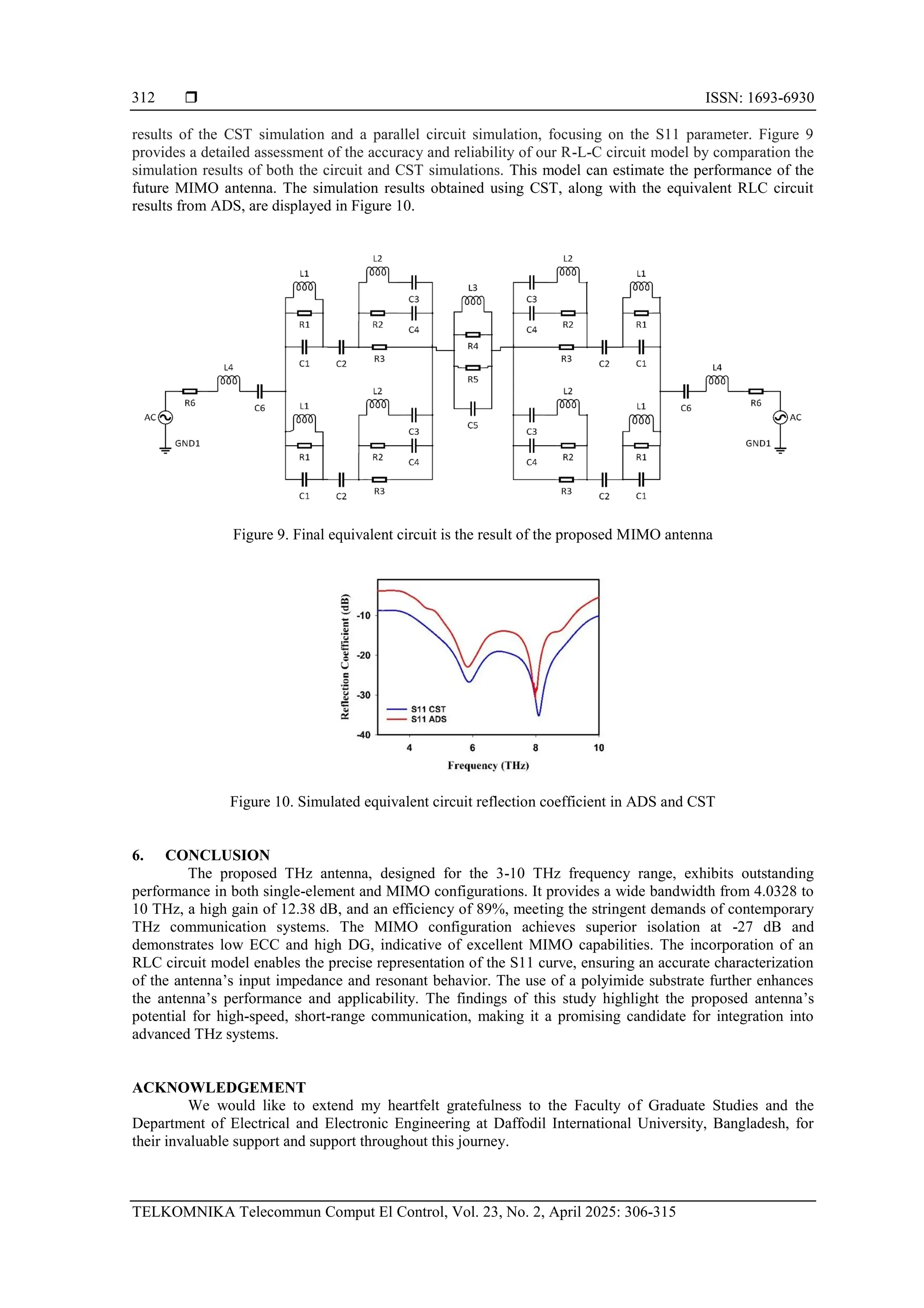
behavior of the system [29]. Figure 9 illustrates the equivalent circuit of the proposed MIMO antenna. The
project aimed to precisely characterize the performance characteristics of the antenna structure and
understand the complex relationships between its electrical components. To ensure accuracy, we
meticulously extracted the R-L-C parameters directly from our antenna simulations using sophisticated tools
such as CST Studio. In our antenna design, the patch element plays a crucial role in achieving two separate
resonance frequencies. We utilized two parallel circuit configurations with resistance (R1), capacitance (C1),
and inductance (L1) to construct these resonance frequencies carefully. Additionally, another two parallel
circuits consisting of (L2+C3), (R2+C4), and R3 are responsible for the slot placed beside the feedline of the
antenna. By combining these circuit elements, we created a model that accurately replicates the behavior of
our single-element antenna [30]. When transitioning to a MIMO configuration, we accounted for mutual
impedance between antenna elements using a parallel circuit of L3, R4, R5, and C5. To verify the accuracy
of the Agilent advanced design system (ADS) simulation, we conducted a comparative test between the](https://image.slidesharecdn.com/5id26562-250624045145-448e9e9c/75/Graphene-based-THz-antenna-with-a-wide-bandwidth-for-future-6G-short-range-communication-6-2048.jpg)
![TELKOMNIKA Telecommun Comput El Control
Graphene-based THz antenna with a wide bandwidth for future 6G short-range … (Md. Kawsar Ahmed)
313
REFERENCES
[1] H. Vettikalladi, W. T. Sethi, A. F. B. Abas, W. Ko, M. A. Alkanhal, and M. Himdi, “Sub-THz Antenna for High-Speed Wireless
Communication Systems,” International Journal of Antennas and Propagation, vol. 2019, no. 1, pp. 1–9, 2019, doi:
10.1155/2019/9573647.
[2] M. Esfandiyari, S. Jarchi, and M. Ghaffari-Miab, “Channel capacity enhancement by adjustable graphene-based MIMO antenna
in THz band,” Optical and Quantum Electronics, vol. 51, no. 5, p. 137, 2019, doi: 10.1007/s11082-019-1856-2.
[3] K. V. Babu, S. Das, G. Varshney, G. N. J. Sree, and B. T. P. Madhav, “A micro-scaled graphene-based tree-shaped wideband
printed MIMO antenna for terahertz applications,” Journal of Computational Electronics, vol. 21, no. 1, pp. 289–303, 2022, doi:
10.1007/s10825-021-01831-3.
[4] Z. Xu, X. Dong and J. Bornemann, “Design of a Reconfigurable MIMO System for THz Communications Based on Graphene
Antennas,” in IEEE Transactions on Terahertz Science and Technology, vol. 4, no. 5, pp. 609-617, Sep. 2014, doi:
10.1109/TTHZ.2014.2331496.
[5] G. Saxena, Y. K. Awasthi, and P. Jain, “High Isolation and High Gain Super-Wideband (0.33-10 THz) MIMO Antenna for THz
Applications,” Optik, vol. 223, p. 165335, Dec. 2020, doi: 10.1016/j.ijleo.2020.165335.
[6] M. S. Rabbani and H. Ghafouri-Shiraz, “Liquid Crystalline Polymer Substrate-Based THz Microstrip Antenna Arrays for Medical
Applications,” in IEEE Antennas and Wireless Propagation Letters, vol. 16, pp. 1533-1536, 2017, doi:
10.1109/LAWP.2017.2647825.
[7] N. K. Maurya, S. Kumari, P. Pareek, and L. Singh, “Graphene-based frequency agile isolation enhancement mechanism for
MIMO antenna in terahertz regime,” Nano Communication Networks, vol. 35, p. 100436, Mar. 2023, doi:
10.1016/j.nancom.2023.100436.
[8] B. Ashvanth and B. Partibane, “Multiband characterized high gain MIMO antenna for terahertz applications,” Optical and
Quantum Electronics, vol. 53, no. 8, p. 460, Aug. 2021, doi: 10.1007/s11082-021-03114-4.
[9] S. Kumar, A. P. Singh, and A. Mishra, “Design and Analysis of Novel Microstrip-Based Dual-Band Compact Terahertz Antenna
for Bioinformatics and Healthcare Applications,” International Journal of Mathematical, Engineering and Management Sciences
(IJMEMS), vol. 8, no. 5, pp. 850–868, Oct. 2023, doi: 10.33889/IJMEMS.2023.8.5.049.
[10] K. V. Babu, G. N. J. Sree, T. Islam, S. Das, M. E. Ghzaoui, and R. A. Saravanan, “Performance Analysis of a Photonic Crystals
Embedded Wideband (1.41–3.0 THz) Fractal MIMO Antenna Over SiO2 Substrate for Terahertz Band Applications,” Silicon,
vol. 15, no. 18, pp. 7823–7836, Dec. 2023, doi: 10.1007/s12633-023-02622-0.
[11] T. Okan, “High efficiency unslotted ultra-wideband microstrip antenna for sub-terahertz short range wireless communication
systems,” Optik, vol. 242, p. 166859, Sep. 2021, doi: 10.1016/j.ijleo.2021.166859.
[12] S. Jorwal, S. Singh, and S. Agarwal, “Design of graphene-based terahertz absorber and machine learning prediction model,”
Optics Communications, vol. 554, p. 130203, Mar. 2024, doi: 10.1016/j.optcom.2023.130203.
[13] K. Vijayalakshmi, C. S. K. Selvi, and B. Sapna, “Novel tri-band series fed microstrip antenna array for THz MIMO
communications,” Optical and Quantum Electronics, vol. 53, no. 7, p. 395, Jul. 2021, doi: 10.1007/s11082-021-03065-w.
[14] R. Jain, V. V. Thakare and P. K. Singhal, “Design and Comparative Analysis of THz Antenna through Machine Learning for 6G
Connectivity,” in IEEE Latin America Transactions, vol. 22, no. 2, pp. 82-91, Feb. 2024, doi: 10.1109/TLA.2024.10412032.
[15] J. Perruisseau-Carrier, “Graphene for antenna applications: Opportunities and challenges from microwaves to THz,” 2012
Loughborough Antennas & Propagation Conference (LAPC), Loughborough, UK, 2012, pp. 1-4, doi:
10.1109/LAPC.2012.6402934.
[16] M. Shalini and M. G. Madhan, “A compact antenna structure for circular polarized terahertz radiation,” Optik, vol. 231, p.
166393, Apr. 2021, doi: 10.1016/j.ijleo.2021.166393.
[17] R. Song et al., “Comparison of copper and graphene-assembled films in 5G wireless communication and THz electromagnetic-
interference shielding,” Proceedings of the National Academy of Sciences (PNAS), U.S.A., vol. 120, no. 9, p. e2209807120, Feb.
2023, doi: 10.1073/pnas.2209807120.
[18] M. Z. Chowdhury, M. Shahjalal, S. Ahmed, and Y. M. Jang, “6G Wireless Communication Systems: Applications, Requirements,
Technologies, Challenges, and Research Directions,” in IEEE Open Journal of the Communications Society, vol. 1, pp. 957-975,
2020, doi: 10.1109/OJCOMS.2020.3010270.
[19] R. Chataut, M. Nankya, and R. Akl, “6G Networks and the AI Revolution—Exploring Technologies, Applications, and Emerging
Challenges,” Sensors, vol. 24, no. 6, p. 1888, Mar. 2024, doi: 10.3390/s24061888.
[20] M. A. Haque et al., “Machine learning-based novel-shaped THz MIMO antenna with a slotted ground plane for future 6G
applications,” Scientific Reports, vol. 14, no. 1, p. 32162, Dec. 2024, doi: 10.1038/s41598-024-79332-z.
[21] P. Kumar, T. Ali, S. Pathan, N. K. Shetty, Y. B. Huchegowda, and Y. Nanjappa, “Design and analysis of ultra-wideband four-port
MIMO antenna with DGS as decoupling structure for THz applications,” Results in Optics, vol. 13, p. 100573, Dec. 2023, doi:
10.1016/j.rio.2023.100573.
[22] E. Holdengreber, X. Gao, M. Mizrahi, S. E. Schacham, and E. Farber, “Superior impedance matching of THz antennas with high
temperature superconducting Josephson junctions,” Superconductor Science and Technology, vol. 32, no. 7, p. 074006, Jul. 2019,
doi: 10.1088/1361-6668/ab1f61.
[23] L. C. Paul, M. A. Haque, M. A. Haque, M. M. U. Rashid, M. F. Islam and M. M. Rahman, “Design a slotted metamaterial
microstrip patch antenna by creating three dual isosceles triangular slots on the patch and bandwidth enhancement,” 2017 3rd
International Conference on Electrical Information and Communication Technology (EICT), Khulna, Bangladesh, 2017, pp. 1-6,
doi: 10.1109/EICT.2017.8275143.
[24] O. Kanhere, H. Poddar, Y. Xing, D. Shakya, S. Ju and T. S. Rappaport, “A Power Efficiency Metric for Comparing Energy
Consumption in Future Wireless Networks in the Millimeter-Wave and Terahertz Bands,” in IEEE Wireless Communications,
vol. 29, no. 6, pp. 56-63, December 2022, doi: 10.1109/MWC.005.2200083.
[25] M. A. Haque et al., “Machine learning-based technique for gain and resonance prediction of mid band 5G Yagi antenna,”
Scientific Reports, vol. 13, no. 1, p. 12590, Aug. 2023, doi: 10.1038/s41598-023-39730-1.
[26] Q. Rubani, S. H. Gupta, and A. Rajawat, “A compact MIMO antenna for WBAN operating at Terahertz frequency,” Optik, vol.
207, p. 164447, Apr. 2020, doi: 10.1016/j.ijleo.2020.164447.
[27] Md. K. Ahmed et al., “ANN-based performance estimation of a slotted inverted F-shaped tri-band antenna for satellite/mm-wave
5G application,” Telecommunication, Computing, Electronics and Control (TELKOMNIKA), vol. 22, no. 4, p. 773, Aug. 2024,
doi: 10.12928/telkomnika.v22i4.26028.
[28] P. U. Jepsen and S. R. Keiding, “Radiation patterns from lens-coupled terahertz antennas,” Optics Letters, vol. 20, no. 8, p. 807,
Apr. 1995, doi: 10.1364/OL.20.000807.](https://image.slidesharecdn.com/5id26562-250624045145-448e9e9c/75/Graphene-based-THz-antenna-with-a-wide-bandwidth-for-future-6G-short-range-communication-8-2048.jpg)
![ ISSN: 1693-6930
TELKOMNIKA Telecommun Comput El Control, Vol. 23, No. 2, April 2025: 306-315
314
[29] M. M. Khader, J. F. Gómez‐Aguilar, and M. Adel, “Numerical study for the fractional RL, RC, and RLC electrical circuits using
Legendre pseudo‐spectral method,” International Journal of Circuit Theory and Applications, vol. 49, no. 10, pp. 3266–3285,
Oct. 2021, doi: 10.1002/cta.3103.
[30] R. Mishra, R. Panwar and D. Singh, “Equivalent Circuit Model for the Design of Frequency-Selective, Terahertz-Band,
Graphene-Based Metamaterial Absorbers,” in IEEE Magnetics Letters, vol. 9, pp. 1-5, 2018, doi: 10.1109/LMAG.2018.2878946.
BIOGRAPHIES OF AUTHORS
Md. Kawsar Ahmed is currently pursuing his studies in the field of Electrical
and Electronic Engineering at Daffodil International University. He successfully finished his
Higher Secondary education at Agricultural University College, Mymensingh. He is presently
employed as an Assistant Administrative Officer at the Office of Students’ Affairs at Daffodil
International University (DIU) in Bangladesh. The areas of his research focus encompassed
microstrip patch antennas, terahertz antennas, and applications related to 4G and 5G
technologies. He can be contacted at email: kawsar33-1241@diu.edu.bd.
Md. Sharif Ahammed is a student of Daffodil International University and
pursuing a B.Sc. in the Electrical and Electronics Department. He passed from Government
Bangabandhu College with a higher secondary. Microstrip patch antenna, terahertz antenna,
and 5G application are some of his research interests. He can be contacted at email: sharif33-
1152@diu.edu.bd.
Md. Ashraful Haque is doing Ph.D. at the Department of Electrical and
Electronic Engineering, Universiti Teknologi PETRONAS, Malaysia, He got his B.Sc. in
Electronics and Electronic Engineering (EEE) from Bangladesh’s Rajshahi University of
Engineering and Technology (RUET) and his M.Sc. in the same field from Bangladesh’s
Islamic University of Technology (IUT). He is currently on leave from Daffodil International
University (DIU) in Bangladesh. His research interest includes microstrip patch antenna, sub 6
5G application, and supervised regression model machine learning on antenna design. He can
be contacted at email: limon.ashraf@gmail.com.
Narinderjit Singh Sawaran Singh is an Associate Professor in INTI
International University, Malaysia. He graduated from the Universiti Teknologi PETRONAS
(UTP) in 2016 with Ph.D. in Electrical and Electronic Engineering specialized in Probabilistic
methods for fault tolerant computing. Currently, he is appointed as the research cluster head
for computational mathematics, technology and optimization which focuses on the areas like
pattern recognition and symbolic computations, game theory, mathematical artificial
intelligence, parallel computing, expert systems and artificial intelligence, quality software,
information technology, exploratory data analysis, optimization algorithms, stochastic
methods, data modelling, and computational intelligence-swarm intelligence. He can be
contacted at email: narinderjits.sawaran@newinti.edu.my.](https://image.slidesharecdn.com/5id26562-250624045145-448e9e9c/75/Graphene-based-THz-antenna-with-a-wide-bandwidth-for-future-6G-short-range-communication-9-2048.jpg)

![TELKOMNIKA Telecommunication Computing Electronics and Control
Vol. 23, No. 2, April 2025, pp. 306~315
ISSN: 1693-6930, DOI: 10.12928/TELKOMNIKA.v23i2.26562 306
Journal homepage: http://telkomnika.uad.ac.id
Graphene-based THz antenna with a wide bandwidth for future
6G short-range communication
Md. Kawsar Ahmed1
, Md. Sharif Ahammed1
, Md. Ashraful Haque1
, Narinderjit Singh Sawaran
Singh2
, Jamal Hossain Nirob1
, Redwan A. Ananta1
, Kamal Hossain Nahin1
, Liton Chandra Paul3
1
Department of Electrical and Electronic Engineering, Daffodil International University, Dhaka, Bangladesh
2
Faculty of Data Science and Information Technology, INTI International University, Nilai, Malaysia
3
Department of Electrical, Electronic and Communication Engineering, Pabna University of Science and Technology, Pabna,
Bangladesh
Article Info ABSTRACT
Article history:
Received Aug 7, 2024
Revised Dec 28, 2024
Accepted Jan 23, 2025
In this study, we present the design and investigation of a terahertz (THz)
frequency antenna optimized for the 2-10 THz range, featuring both single-
element and multiple-input multiple-output (MIMO) configurations, with a
focus on industrial and innovative applications to enhance future 6G
communication systems. The antenna, constructed on a polyimide substrate
with dimensions of 90×30 µm, achieves a bandwidth from 4.0328 to 10
THz. The MIMO configuration, which includes two ports, demonstrates
excellent isolation with a value of -27 dB. The proposed antenna system
achieves a gain of 12.38 dB and an efficiency of 89%, making it highly
appropriate for THz communication applications. Furthermore, the envelope
correlation coefficient (ECC) of 0.002 and diversity gain (DG) of 9.99
affirm the antenna’s effectiveness in MIMO systems. A resistance
inductance capacitance (RLC) circuit model was employed to accurately
represent the S11 curve, ensuring precise characterization of the antenna’s
performance. These results underscore the probability of the proposed
antenna for high-speed, short-range communication systems.
Keywords:
Graphene
High bandwidth
Industrial and innovation
Microstrip patch antenna
Multiple-input multiple-output
antenna
Resistance inductance
capacitance This is an open access article under the CC BY-SA license.
Corresponding Author:
Narinderjit Singh Sawaran Singh
Faculty of Data Science and Information Technology, INTI International University
Persiaran Perdana BBN, Putra Nilai, Nilai 71800, Negeri Sembilan, Malaysia
Email: narinderjits.sawaran@newinti.edu.my
1. INTRODUCTION
The rapid growth of wireless communication technologies has spurred the exploration of novel
frequency bands to meet the growing demand for high data rates and huge bandwidths [1]. Among these, the
terahertz (THz) frequency range, ranging from 0.1 to 10 THz, has garnered significant interest due to its
potential to support ultra-fast data transmission and high-capacity communication systems [2]. Unlike
conventional microwave and millimeter-wave frequencies, the THz band offers an extensive bandwidth that
can facilitate data rates exceeding hundreds of gigabits per second (Gbps) [3]. This makes it particularly
suitable for emerging applications such as ultra-high-definition video streaming, high-speed wireless
networks, and next-generation mobile communications [4].
However, designing antennas that operate efficiently at THz frequencies poses several challenges,
including high propagation losses, fabrication precision, and material selection [5]. The choice of substrate
material is vital, as it affects the antenna’s impedance matching, bandwidth, and radiation efficiency [6]. In
this study, we employ a polyimide substrate due to its favorable dielectric properties, low-loss tangent, and
mechanical flexibility, making it an ideal candidate for THz applications [7].](https://crownmelresort.com/image.slidesharecdn.com/5id26562-250624045145-448e9e9c/75/Graphene-based-THz-antenna-with-a-wide-bandwidth-for-future-6G-short-range-communication-1-2048.jpg)
![TELKOMNIKA Telecommun Comput El Control
Graphene-based THz antenna with a wide bandwidth for future 6G short-range … (Md. Kawsar Ahmed)
307
Multiple-input multiple-output (MIMO) technology has become a cornerstone in modern wireless
communications, offering significant enhancements in channel capacity, spectral efficiency, and signal
reliability [8]. By deploying multiple antennas at together the transmitter and receiver, MIMO systems
activity spatial diversity and multiplexing gains. This technology is especially promising in the THz domain,
where it can mitigate the effects of high path loss and limited power output of THz sources [9]. Our research
attention is on the design and investigation of a THz antenna system that incorporates MIMO technology,
aiming to achieve high gain, broad bandwidth, and low mutual coupling between elements.
A key aspect of antenna design is the accurate modeling of its impedance characteristics, typically
represented by the S11 parameter. In this work, we employ a resistance inductance capacitance (RLC) circuit
model to simulate the S11 curve of the proposed MIMO antenna, providing a detailed understanding of its
resonant behavior and input impedance. The RLC model helps to capture the complex interaction between
the antenna elements and the substrate, offering insights into optimizing the design for improved
performance.
This paper presents a comprehensive investigation of a THz antenna system, covering both single-
element and MIMO configurations. The proposed antenna demonstrates a bandwidth range of
4.0328-10 THz, which is better compared to [10]-[14], which is shown in Table 1, a gain of 12.38 dB better
then [10], [11], [13], and an efficiency of 89% [10], [11], [13]. The MIMO configuration, with two ports,
achieves excellent isolation of -27 dB, an envelope correlation coefficient (ECC) of 0.002, and a diversity
gain (DG) of 9.99, indicating robust MIMO performance. These characteristics highlight the antenna’s
potential for high-speed, short-range communication systems.
Table 1. Performance evalution of the proposed MIMO antenna in comparison to related work
2. DESIGN METHOD
2.1. Single element design
In our single-element antenna design process, we start with a circular patch shape, changing its
shape in several steps to improve performance. We use graphene for the patch material, a circular patch
shape with radius ‘r’, placed on a substrate, and copper as the ground material. Both patch and ground have a
thickness of 0.75 micrometers and substrate dimensions are 30 micrometers in length and 25 micrometers in
width [15]. A circular slot is in the center of the substrate and two square slots are on either side of the feed
line, flanked by two insets. Further modifications include a rectangular ground plane (30 by 25 micrometers)
with a central circular structure of radius ‘r’ [16]. There is also an inset ground along the feed line. These
modifications and our target improve impedance matching, bandwidth, gain, and radiation pattern. We then
simulate the antenna using CST software to evaluate the return loss, radiation pattern, and gain, gaining
insight into its behavior across different conditions and frequencies. We can see the design in Figure 1.
2.2. Analysis of the result of the single element by using graphene and copper
First, we attempted to design a single-element antenna, using copper for both the patch and ground.
In the second stage design patch and ground graphene. In the third stage we use copper we use patch
materials graphene and ground materials, copper. At this stage, we tried to find the best results in graphene
and copper combinations [17]. We can see the design changes in Figure 2. In the first step for Figure 2(a) and
for the second step Figure 2(b) we get the result return loss -38 dB and -44 dB. In the third stage, we get the
result frequencies 5.66 and 7.94 return loss -66.48 and -75.25 dB for proposed Figure 2(c), this is our propped
single-element antenna result and shown graphically in Figure 2(d). Substrate width (sw)=25 micrometer,
substrate thickness (st)=3 micrometer radios (r)=10 micrometer slot1 (s11)=2 micrometer, ground width
Ref Resonance
(THz)
BW
(THz)
Isolation
(dB)
Gain
(dB)
Efficienc
y (%)
ECC
(dB)
DG
(dB)
Substrate
material
Board
size
(μm2
)
MIMO
configuration
[10] 1.89 1.59 -25 4.60 74.5 15.6×
10-10
≈10 SiO2 38×25 -
[11] - 0.114 -17 4.4 94 0.006 9.97 Rogers
RO4835-T
2000×1
000
2×2
[12] 10.51 1 - - - - - Silicon
dioxide
- -
[13] 2.3, 3.2, 4.5 0.038,
0.043,
0.06
-17, -30, -
23
5 60 0.2 9.99 Polyimide 50×40
[14] 2.8 1.5 - - - - - RT/duriod6
010
- -
Proposed 8.096 (4.032
8-10)
-27.62 12.38 -89.0 9.99 Polyimide 90×30 2×2](https://crownmelresort.com/image.slidesharecdn.com/5id26562-250624045145-448e9e9c/75/Graphene-based-THz-antenna-with-a-wide-bandwidth-for-future-6G-short-range-communication-2-2048.jpg)
![ ISSN: 1693-6930
TELKOMNIKA Telecommun Comput El Control, Vol. 23, No. 2, April 2025: 306-315
308
(bw)=25 micrometer, ground length (bl)=30 micrometer, patch thickness (t)=0.75 micrometer, feedline width
(fw)=3 micrometer feedline length (fl)=6 micrometer, edge-to-edge gap1 (d)=3.5 micrometer, edge-to-edge
gap2 (d2)=4 micrometer, inset length (x)=0.5 micrometer, and inset width (y)=4 micrometer.
Figure 1. Front and ground views of single-element configuration
(a) (b) (c)
(d)
Figure 2. Evolutionary progression and result of single element; (a) first step, (b) second step, (c) proposed
singlement element antenna, and (d) graphics
2.3. Single element vs multiple-input multiple-output
In our current endeavors focused on global 5G applications, our developmental trajectory is centered
on advancing antenna technology for forthcoming 6G applications [18]. In this section, we will try to find the
difference between single-element antenna and MIMO. Initially, a shift from single-element antennas to
MIMO configurations, marked a transformative progression. This advancement is primarily motivated by the
pursuit of enhanced performance, efficiency, and adaptability within wireless communication systems.
Additionally, cognitive technologies such as AI are leveraged to enable high-speed, low-latency
communications operating at existing radio frequencies and achieving speeds significantly surpassing those
of fifth-generation networks [19]. The transition from single-element antennas to MIMO configurations
allows us to harness spatial diversity, multiplexing gain, and improved spectral efficiency. These attributes
are crucial for meeting the escalating demands for higher data rates, reduced latency, and expanded network
capacity in 6G networks. From our single-element antenna to MIMO, our range of mobility and work is
wide.](https://crownmelresort.com/image.slidesharecdn.com/5id26562-250624045145-448e9e9c/75/Graphene-based-THz-antenna-with-a-wide-bandwidth-for-future-6G-short-range-communication-3-2048.jpg)
![TELKOMNIKA Telecommun Comput El Control
Graphene-based THz antenna with a wide bandwidth for future 6G short-range … (Md. Kawsar Ahmed)
309
2.4. Multiple-input multiple-output antenna
In this section, we will explain the conversion technique in a MIMO formation. At this stage, it is
decided to convert to a MIMO configuration for increasing antenna performance and spatial diversity,
increasing capacity, facilitating multipath exploitation, and more extensive, more unknown information or
search results. The section details the details of the microstrip MIMO patch antenna. In our MIMO antenna
design methodology, we explain how to build a 2-port MIMO configuration using a single-element antenna
as a basic element, with the goal of spatial diversity, interference mitigation, power enhancement, multipath
absorption, and signal reception through height to do [20]. Improve protection This important advance is
motivated by the need to ensure the optimal orientation of the antenna elements, thus achieving the necessary
level of isolation important for superior performance. To realize the optimal MIMO antenna configuration,
we initially used two single-element antennas. The basic patch and ground structure of a single-element
antenna is laid out like a single-element antenna. Next, we use decoupling in MIMO to improve the results.
At this stage, the decoupling length and width were changed to 30 micrometers and 40 micrometers, and the
decoupling area ground was all copper [21]. Conversion to a MIMO formation achieves the best results. We
can see the proposed MIMO antenna in Figure 3.
Figure 3. Comparative analysis MIMO antenna and performance antenna configurations
3. RESULT ANALYSIS OF PROPOSED MIMO ANTENNA
3.1. Reflection and transmission coefficient
The reflection coefficient, also acknowledged as the S₁₁ parameter, serves as a pivotal metric in
evaluating antenna performance, offering valuable insights into the efficacy of power transfer between the
transmission line and the antenna. It governs the magnitude of radio frequency (RF) power redirected from a
microstrip patch antenna back toward the feed line. Defined as a ratio expressed in decibels (dB), it
juxtaposes reflected power against incident power from the feed line. A diminished reflection coefficient,
denoted by a negative dB value, signifies minimal power reflection and optimal impedance matching, which
is pivotal for efficient power transfer and antenna performance [22]. Conventionally, an exemplary value for
a well-matched antenna is deemed to be -10 dB or lower. The meticulously engineered microstrip patch
antenna showcases auspicious attributes, characterized by dual resonant frequencies situated at 8.096 THz, as
depicted in Figure 4. At both resonance frequencies, commendable return loss values are attained, peaking at
-35.23 dB at 8.096 THz. Such performance translates into efficient signal transmission and negligible
reflections at the resonant frequencies, significantly enhancing the antenna’s overall efficacy. Furthermore,
the antenna boasts a commendable bandwidth spanning 5.968 THz (ranging from 4.0315 THz to 10 THz),
denoting the spectrum of frequencies over which it maintains satisfactory performance [23].
3.2. Gain and efficiency
Gain is a crucial factor in the performance of MIMO systems, impacting coverage, signal strength,
and data rate. It measures the system’s ability to effectively focus and direct transmitted and received signals,
reducing unwanted noise from other directions. Higher gain results in stronger signals reaching a wider area,
thus extending the system’s coverage range. The simulated gain for the proposed MIMO antenna is
illustrated in Figure 5. The antenna demonstrates a peak gain of 12.38 dB, with gains of 11.92 dB at resonant
frequencies of 8.096 THz respectively. This suggests a potentially more focused radiation pattern, making the
antenna suitable for applications requiring extended coverage. Efficiency is also crucial in MIMO systems,
directly impacting power consumption, data rate, and overall performance [24]. It measures how effectively
the system converts input power into useful transmitted or received signal power. In the case of microstrip
patch antennas, efficiency is particularly significant as it directly influences overall antenna performance.](https://crownmelresort.com/image.slidesharecdn.com/5id26562-250624045145-448e9e9c/75/Graphene-based-THz-antenna-with-a-wide-bandwidth-for-future-6G-short-range-communication-4-2048.jpg)
![ ISSN: 1693-6930
TELKOMNIKA Telecommun Comput El Control, Vol. 23, No. 2, April 2025: 306-315
310
A higher efficiency indicates a greater proportion of input power being converted into useful radiated power,
enhancing signal strength and communication quality [25]. The simulated efficiency gains for the proposed
MIMO antenna, depicted in Figure 5, show a high efficiency of 89%, consistently exceeding 86% across its
range. This indicates superior performance in changing input power into useful radiated power, contributing
to enhanced signal strength and communication quality.
Figure 4. Reflection coefficient of the proposed
MIMO antenna
Figure 5. Efficiency and gain of the proposed MIMO
antenna
3.3. The envelope correlation coefficient
The ECC holds significant importance in MIMO systems, as it directly impacts the system’s
capability to leverage spatial diversity and achieve optimal channel capacity [26]. It quantifies the association
between the envelopes of signals received by different antennas within the MIMO system. Essentially, it
measures the similarity or correlation in the amplitudes of received signals across multiple antennas. In the
context of MIMO systems, a low ECC, preferably close to zero, is desirable for optimal performance. We can
see the ECC in Figure 6. This is because a low ECC indicates a high level of diversity among the multiple
antennas, which is advantageous for maximizing system performance.
3.4. Diversity gain
DG is essentially what we use to measure the development in system performance due to the
practice of multiple antennas and to experience independent fading. Additionally, MIMO systems contribute
significantly to improved system reliability, coverage, and capacity. One of the primary goals of MIMO
systems is to achieve DG. The value of DG can be calculated below.
The simulated DG for the suggested MIMO antenna is shown in Figure 7. It can be seen that the
antenna achieves the lowest DG of 9.99. This value of DG suggests a considerable improvement in signal
reliability and robustness due to the use of multiple antennas in a MIMO system [5].
Figure 6. ECC of the proposed MIMO antenna Figure 7. DG of the proposed MIMO antenna](https://crownmelresort.com/image.slidesharecdn.com/5id26562-250624045145-448e9e9c/75/Graphene-based-THz-antenna-with-a-wide-bandwidth-for-future-6G-short-range-communication-5-2048.jpg)
![TELKOMNIKA Telecommun Comput El Control
Graphene-based THz antenna with a wide bandwidth for future 6G short-range … (Md. Kawsar Ahmed)
311
4. RADIATION PATTERN
The radiation pattern of an antenna is a graphical representation of the radiation dispersion from the
antenna with respect to spatial direction. It is important to consider the orientation and properties of the E
field and the H field when designing and placing antennas [27]. A magnitude of 22.4 dB V/m is associated
with the E field lobe at theta =90°, a half-power beam width of 52°, and an H field magnitude of 900. As for
the main lobe magnitude, it is -38.5 dBA/m, and the HPBW is 54.30 degrees. The half-power beam width is
124.6°, the E field of the primary lobe at =90° in the H-field is 8 dBV/m, and the magnitude for the H field of
the lobe at =90° is -29.2 dB A/m. Figure 8 shows that the E-field, with theta =0 degrees, has an HPBW of
89.9 degrees and a primary lobe magnitude of 17.1 dB V/m [28].
Figure 8. Simulated radiation pattern of recommended MIMO antenna
5. RESISTANCE INDUCTANCE CAPACITANCE EQUIVALENT CIRCUIT
In this section, we design an advanced antenna system to meet future wireless communication
requirements. Our initial step involved developing an RLC circuit model to analyze the electromagnetic
behavior of the system [29]. Figure 9 illustrates the equivalent circuit of the proposed MIMO antenna. The
project aimed to precisely characterize the performance characteristics of the antenna structure and
understand the complex relationships between its electrical components. To ensure accuracy, we
meticulously extracted the R-L-C parameters directly from our antenna simulations using sophisticated tools
such as CST Studio. In our antenna design, the patch element plays a crucial role in achieving two separate
resonance frequencies. We utilized two parallel circuit configurations with resistance (R1), capacitance (C1),
and inductance (L1) to construct these resonance frequencies carefully. Additionally, another two parallel
circuits consisting of (L2+C3), (R2+C4), and R3 are responsible for the slot placed beside the feedline of the
antenna. By combining these circuit elements, we created a model that accurately replicates the behavior of
our single-element antenna [30]. When transitioning to a MIMO configuration, we accounted for mutual
impedance between antenna elements using a parallel circuit of L3, R4, R5, and C5. To verify the accuracy
of the Agilent advanced design system (ADS) simulation, we conducted a comparative test between the](https://crownmelresort.com/image.slidesharecdn.com/5id26562-250624045145-448e9e9c/75/Graphene-based-THz-antenna-with-a-wide-bandwidth-for-future-6G-short-range-communication-6-2048.jpg)

![TELKOMNIKA Telecommun Comput El Control
Graphene-based THz antenna with a wide bandwidth for future 6G short-range … (Md. Kawsar Ahmed)
313
REFERENCES
[1] H. Vettikalladi, W. T. Sethi, A. F. B. Abas, W. Ko, M. A. Alkanhal, and M. Himdi, “Sub-THz Antenna for High-Speed Wireless
Communication Systems,” International Journal of Antennas and Propagation, vol. 2019, no. 1, pp. 1–9, 2019, doi:
10.1155/2019/9573647.
[2] M. Esfandiyari, S. Jarchi, and M. Ghaffari-Miab, “Channel capacity enhancement by adjustable graphene-based MIMO antenna
in THz band,” Optical and Quantum Electronics, vol. 51, no. 5, p. 137, 2019, doi: 10.1007/s11082-019-1856-2.
[3] K. V. Babu, S. Das, G. Varshney, G. N. J. Sree, and B. T. P. Madhav, “A micro-scaled graphene-based tree-shaped wideband
printed MIMO antenna for terahertz applications,” Journal of Computational Electronics, vol. 21, no. 1, pp. 289–303, 2022, doi:
10.1007/s10825-021-01831-3.
[4] Z. Xu, X. Dong and J. Bornemann, “Design of a Reconfigurable MIMO System for THz Communications Based on Graphene
Antennas,” in IEEE Transactions on Terahertz Science and Technology, vol. 4, no. 5, pp. 609-617, Sep. 2014, doi:
10.1109/TTHZ.2014.2331496.
[5] G. Saxena, Y. K. Awasthi, and P. Jain, “High Isolation and High Gain Super-Wideband (0.33-10 THz) MIMO Antenna for THz
Applications,” Optik, vol. 223, p. 165335, Dec. 2020, doi: 10.1016/j.ijleo.2020.165335.
[6] M. S. Rabbani and H. Ghafouri-Shiraz, “Liquid Crystalline Polymer Substrate-Based THz Microstrip Antenna Arrays for Medical
Applications,” in IEEE Antennas and Wireless Propagation Letters, vol. 16, pp. 1533-1536, 2017, doi:
10.1109/LAWP.2017.2647825.
[7] N. K. Maurya, S. Kumari, P. Pareek, and L. Singh, “Graphene-based frequency agile isolation enhancement mechanism for
MIMO antenna in terahertz regime,” Nano Communication Networks, vol. 35, p. 100436, Mar. 2023, doi:
10.1016/j.nancom.2023.100436.
[8] B. Ashvanth and B. Partibane, “Multiband characterized high gain MIMO antenna for terahertz applications,” Optical and
Quantum Electronics, vol. 53, no. 8, p. 460, Aug. 2021, doi: 10.1007/s11082-021-03114-4.
[9] S. Kumar, A. P. Singh, and A. Mishra, “Design and Analysis of Novel Microstrip-Based Dual-Band Compact Terahertz Antenna
for Bioinformatics and Healthcare Applications,” International Journal of Mathematical, Engineering and Management Sciences
(IJMEMS), vol. 8, no. 5, pp. 850–868, Oct. 2023, doi: 10.33889/IJMEMS.2023.8.5.049.
[10] K. V. Babu, G. N. J. Sree, T. Islam, S. Das, M. E. Ghzaoui, and R. A. Saravanan, “Performance Analysis of a Photonic Crystals
Embedded Wideband (1.41–3.0 THz) Fractal MIMO Antenna Over SiO2 Substrate for Terahertz Band Applications,” Silicon,
vol. 15, no. 18, pp. 7823–7836, Dec. 2023, doi: 10.1007/s12633-023-02622-0.
[11] T. Okan, “High efficiency unslotted ultra-wideband microstrip antenna for sub-terahertz short range wireless communication
systems,” Optik, vol. 242, p. 166859, Sep. 2021, doi: 10.1016/j.ijleo.2021.166859.
[12] S. Jorwal, S. Singh, and S. Agarwal, “Design of graphene-based terahertz absorber and machine learning prediction model,”
Optics Communications, vol. 554, p. 130203, Mar. 2024, doi: 10.1016/j.optcom.2023.130203.
[13] K. Vijayalakshmi, C. S. K. Selvi, and B. Sapna, “Novel tri-band series fed microstrip antenna array for THz MIMO
communications,” Optical and Quantum Electronics, vol. 53, no. 7, p. 395, Jul. 2021, doi: 10.1007/s11082-021-03065-w.
[14] R. Jain, V. V. Thakare and P. K. Singhal, “Design and Comparative Analysis of THz Antenna through Machine Learning for 6G
Connectivity,” in IEEE Latin America Transactions, vol. 22, no. 2, pp. 82-91, Feb. 2024, doi: 10.1109/TLA.2024.10412032.
[15] J. Perruisseau-Carrier, “Graphene for antenna applications: Opportunities and challenges from microwaves to THz,” 2012
Loughborough Antennas & Propagation Conference (LAPC), Loughborough, UK, 2012, pp. 1-4, doi:
10.1109/LAPC.2012.6402934.
[16] M. Shalini and M. G. Madhan, “A compact antenna structure for circular polarized terahertz radiation,” Optik, vol. 231, p.
166393, Apr. 2021, doi: 10.1016/j.ijleo.2021.166393.
[17] R. Song et al., “Comparison of copper and graphene-assembled films in 5G wireless communication and THz electromagnetic-
interference shielding,” Proceedings of the National Academy of Sciences (PNAS), U.S.A., vol. 120, no. 9, p. e2209807120, Feb.
2023, doi: 10.1073/pnas.2209807120.
[18] M. Z. Chowdhury, M. Shahjalal, S. Ahmed, and Y. M. Jang, “6G Wireless Communication Systems: Applications, Requirements,
Technologies, Challenges, and Research Directions,” in IEEE Open Journal of the Communications Society, vol. 1, pp. 957-975,
2020, doi: 10.1109/OJCOMS.2020.3010270.
[19] R. Chataut, M. Nankya, and R. Akl, “6G Networks and the AI Revolution—Exploring Technologies, Applications, and Emerging
Challenges,” Sensors, vol. 24, no. 6, p. 1888, Mar. 2024, doi: 10.3390/s24061888.
[20] M. A. Haque et al., “Machine learning-based novel-shaped THz MIMO antenna with a slotted ground plane for future 6G
applications,” Scientific Reports, vol. 14, no. 1, p. 32162, Dec. 2024, doi: 10.1038/s41598-024-79332-z.
[21] P. Kumar, T. Ali, S. Pathan, N. K. Shetty, Y. B. Huchegowda, and Y. Nanjappa, “Design and analysis of ultra-wideband four-port
MIMO antenna with DGS as decoupling structure for THz applications,” Results in Optics, vol. 13, p. 100573, Dec. 2023, doi:
10.1016/j.rio.2023.100573.
[22] E. Holdengreber, X. Gao, M. Mizrahi, S. E. Schacham, and E. Farber, “Superior impedance matching of THz antennas with high
temperature superconducting Josephson junctions,” Superconductor Science and Technology, vol. 32, no. 7, p. 074006, Jul. 2019,
doi: 10.1088/1361-6668/ab1f61.
[23] L. C. Paul, M. A. Haque, M. A. Haque, M. M. U. Rashid, M. F. Islam and M. M. Rahman, “Design a slotted metamaterial
microstrip patch antenna by creating three dual isosceles triangular slots on the patch and bandwidth enhancement,” 2017 3rd
International Conference on Electrical Information and Communication Technology (EICT), Khulna, Bangladesh, 2017, pp. 1-6,
doi: 10.1109/EICT.2017.8275143.
[24] O. Kanhere, H. Poddar, Y. Xing, D. Shakya, S. Ju and T. S. Rappaport, “A Power Efficiency Metric for Comparing Energy
Consumption in Future Wireless Networks in the Millimeter-Wave and Terahertz Bands,” in IEEE Wireless Communications,
vol. 29, no. 6, pp. 56-63, December 2022, doi: 10.1109/MWC.005.2200083.
[25] M. A. Haque et al., “Machine learning-based technique for gain and resonance prediction of mid band 5G Yagi antenna,”
Scientific Reports, vol. 13, no. 1, p. 12590, Aug. 2023, doi: 10.1038/s41598-023-39730-1.
[26] Q. Rubani, S. H. Gupta, and A. Rajawat, “A compact MIMO antenna for WBAN operating at Terahertz frequency,” Optik, vol.
207, p. 164447, Apr. 2020, doi: 10.1016/j.ijleo.2020.164447.
[27] Md. K. Ahmed et al., “ANN-based performance estimation of a slotted inverted F-shaped tri-band antenna for satellite/mm-wave
5G application,” Telecommunication, Computing, Electronics and Control (TELKOMNIKA), vol. 22, no. 4, p. 773, Aug. 2024,
doi: 10.12928/telkomnika.v22i4.26028.
[28] P. U. Jepsen and S. R. Keiding, “Radiation patterns from lens-coupled terahertz antennas,” Optics Letters, vol. 20, no. 8, p. 807,
Apr. 1995, doi: 10.1364/OL.20.000807.](https://crownmelresort.com/image.slidesharecdn.com/5id26562-250624045145-448e9e9c/75/Graphene-based-THz-antenna-with-a-wide-bandwidth-for-future-6G-short-range-communication-8-2048.jpg)
![ ISSN: 1693-6930
TELKOMNIKA Telecommun Comput El Control, Vol. 23, No. 2, April 2025: 306-315
314
[29] M. M. Khader, J. F. Gómez‐Aguilar, and M. Adel, “Numerical study for the fractional RL, RC, and RLC electrical circuits using
Legendre pseudo‐spectral method,” International Journal of Circuit Theory and Applications, vol. 49, no. 10, pp. 3266–3285,
Oct. 2021, doi: 10.1002/cta.3103.
[30] R. Mishra, R. Panwar and D. Singh, “Equivalent Circuit Model for the Design of Frequency-Selective, Terahertz-Band,
Graphene-Based Metamaterial Absorbers,” in IEEE Magnetics Letters, vol. 9, pp. 1-5, 2018, doi: 10.1109/LMAG.2018.2878946.
BIOGRAPHIES OF AUTHORS
Md. Kawsar Ahmed is currently pursuing his studies in the field of Electrical
and Electronic Engineering at Daffodil International University. He successfully finished his
Higher Secondary education at Agricultural University College, Mymensingh. He is presently
employed as an Assistant Administrative Officer at the Office of Students’ Affairs at Daffodil
International University (DIU) in Bangladesh. The areas of his research focus encompassed
microstrip patch antennas, terahertz antennas, and applications related to 4G and 5G
technologies. He can be contacted at email: kawsar33-1241@diu.edu.bd.
Md. Sharif Ahammed is a student of Daffodil International University and
pursuing a B.Sc. in the Electrical and Electronics Department. He passed from Government
Bangabandhu College with a higher secondary. Microstrip patch antenna, terahertz antenna,
and 5G application are some of his research interests. He can be contacted at email: sharif33-
1152@diu.edu.bd.
Md. Ashraful Haque is doing Ph.D. at the Department of Electrical and
Electronic Engineering, Universiti Teknologi PETRONAS, Malaysia, He got his B.Sc. in
Electronics and Electronic Engineering (EEE) from Bangladesh’s Rajshahi University of
Engineering and Technology (RUET) and his M.Sc. in the same field from Bangladesh’s
Islamic University of Technology (IUT). He is currently on leave from Daffodil International
University (DIU) in Bangladesh. His research interest includes microstrip patch antenna, sub 6
5G application, and supervised regression model machine learning on antenna design. He can
be contacted at email: limon.ashraf@gmail.com.
Narinderjit Singh Sawaran Singh is an Associate Professor in INTI
International University, Malaysia. He graduated from the Universiti Teknologi PETRONAS
(UTP) in 2016 with Ph.D. in Electrical and Electronic Engineering specialized in Probabilistic
methods for fault tolerant computing. Currently, he is appointed as the research cluster head
for computational mathematics, technology and optimization which focuses on the areas like
pattern recognition and symbolic computations, game theory, mathematical artificial
intelligence, parallel computing, expert systems and artificial intelligence, quality software,
information technology, exploratory data analysis, optimization algorithms, stochastic
methods, data modelling, and computational intelligence-swarm intelligence. He can be
contacted at email: narinderjits.sawaran@newinti.edu.my.](https://crownmelresort.com/image.slidesharecdn.com/5id26562-250624045145-448e9e9c/75/Graphene-based-THz-antenna-with-a-wide-bandwidth-for-future-6G-short-range-communication-9-2048.jpg)


