Downloaded 194 times
![Network: physical connection that allows two computers to
communicate
Packet: unit of transfer, bits carried over the network
Network carries packets from on CPU to another
Destination gets interrupt when packet arrives
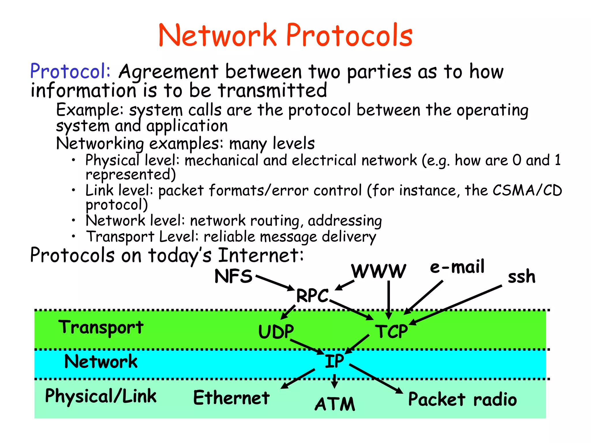
Protocol: agreement between two parties as to how
information is to be transmitted
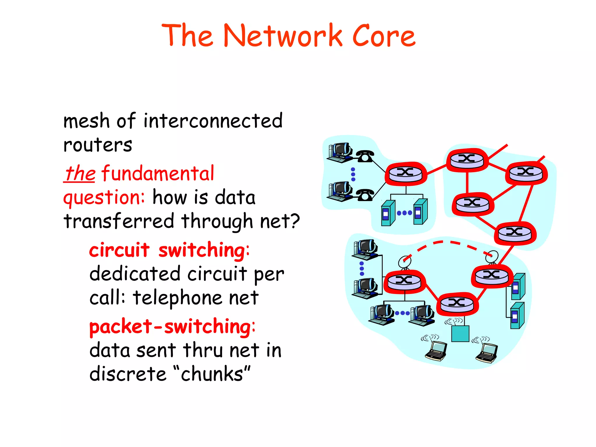
Broadcast Network: Shared Communication Medium
Delivery: How does a receiver know who packet is for?
Put header on front of packet: [ Destination | Packet ]
Everyone gets packet, discards if not the target
Arbitration: Act of negotiating use of shared medium
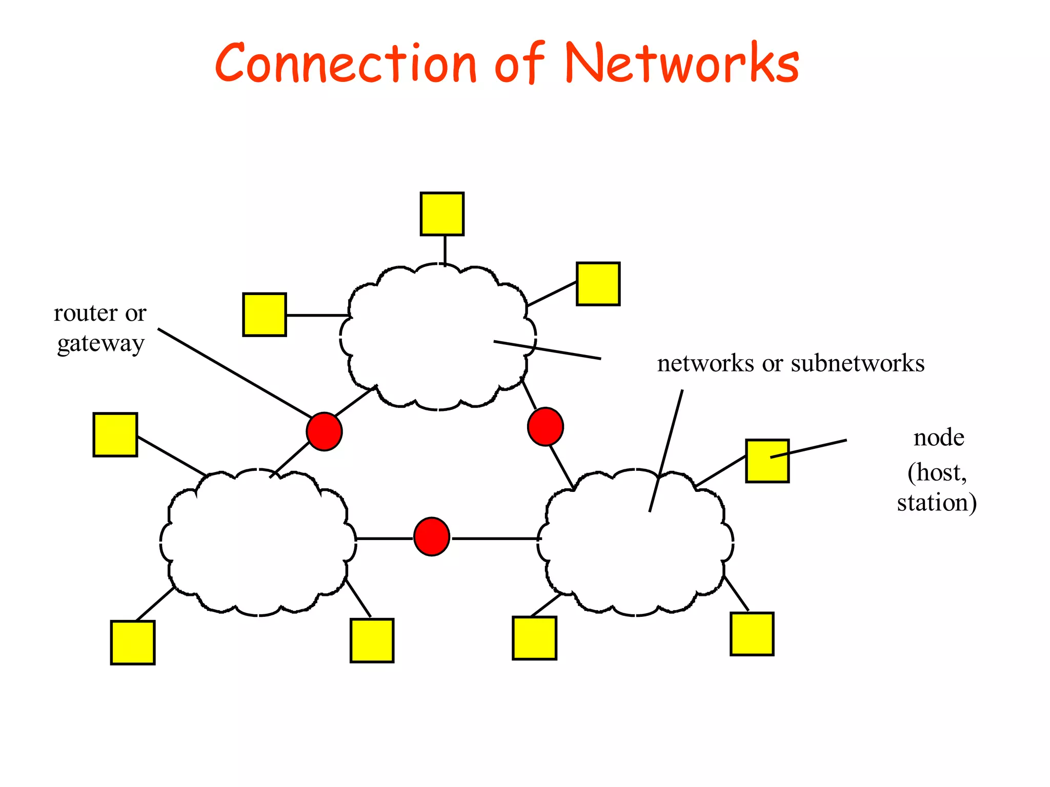
Point-to-point network: a network in which every physical
wire is connected to only two computers
Switch: a bridge that transforms a shared-bus
(broadcast) configuration into a point-to-point network
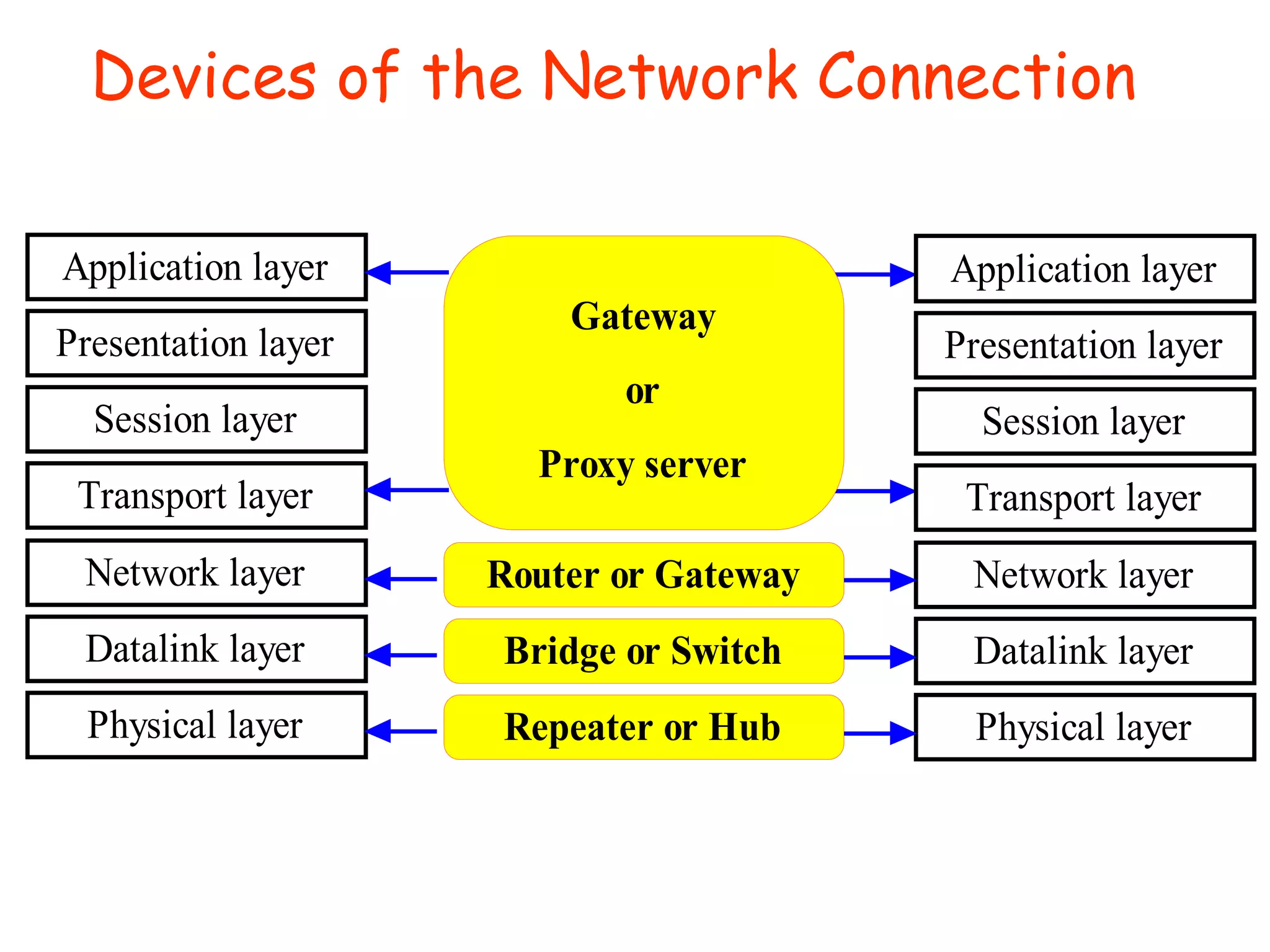
Router: a device that acts as a junction between two
networks to transfer data packets among them
Review: Networking Definitions](https://image.slidesharecdn.com/computernetworkbasics-131001092354-phpapp01/75/Computer-network-basics-18-2048.jpg)
![Building a messaging service
Process to process communication
Basic routing gets packets from machine→machine
What we really want is routing from process→process
• Example: ssh, email, ftp, web browsing
Several IP protocols include notion of a “port”, which is
a 16-bit identifiers used in addition to IP addresses
• A communication channel (connection) defined by 5 items:
[source address, source port, dest address, dest port, protocol]
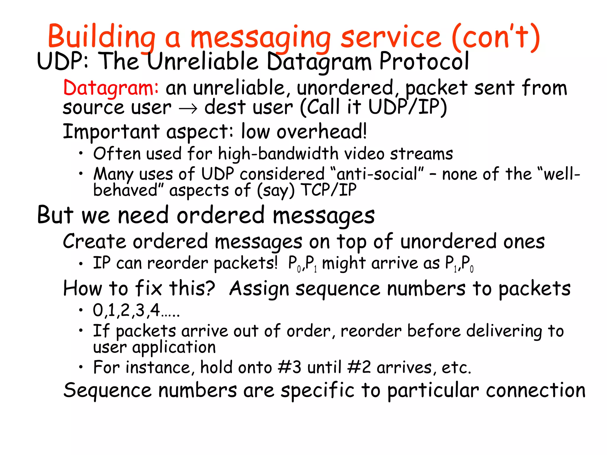
UDP: The User Datagram Protocol
UDP layered on top of basic IP (IP Protocol 17)
• Unreliable, unordered, user-to-user communication
UDP Data
16-bit UDP length 16-bit UDP checksum
16-bit source port 16-bit destination port
IP Header
(20 bytes)](https://image.slidesharecdn.com/computernetworkbasics-131001092354-phpapp01/75/Computer-network-basics-59-2048.jpg)


![Network: physical connection that allows two computers to
communicate
Packet: unit of transfer, bits carried over the network
Network carries packets from on CPU to another
Destination gets interrupt when packet arrives
Protocol: agreement between two parties as to how
information is to be transmitted
Broadcast Network: Shared Communication Medium
Delivery: How does a receiver know who packet is for?
Put header on front of packet: [ Destination | Packet ]
Everyone gets packet, discards if not the target
Arbitration: Act of negotiating use of shared medium
Point-to-point network: a network in which every physical
wire is connected to only two computers
Switch: a bridge that transforms a shared-bus
(broadcast) configuration into a point-to-point network
Router: a device that acts as a junction between two
networks to transfer data packets among them
Review: Networking Definitions](https://crownmelresort.com/image.slidesharecdn.com/computernetworkbasics-131001092354-phpapp01/75/Computer-network-basics-18-2048.jpg)


![Building a messaging service
Process to process communication
Basic routing gets packets from machine→machine
What we really want is routing from process→process
• Example: ssh, email, ftp, web browsing
Several IP protocols include notion of a “port”, which is
a 16-bit identifiers used in addition to IP addresses
• A communication channel (connection) defined by 5 items:
[source address, source port, dest address, dest port, protocol]
UDP: The User Datagram Protocol
UDP layered on top of basic IP (IP Protocol 17)
• Unreliable, unordered, user-to-user communication
UDP Data
16-bit UDP length 16-bit UDP checksum
16-bit source port 16-bit destination port
IP Header
(20 bytes)](https://crownmelresort.com/image.slidesharecdn.com/computernetworkbasics-131001092354-phpapp01/75/Computer-network-basics-59-2048.jpg)


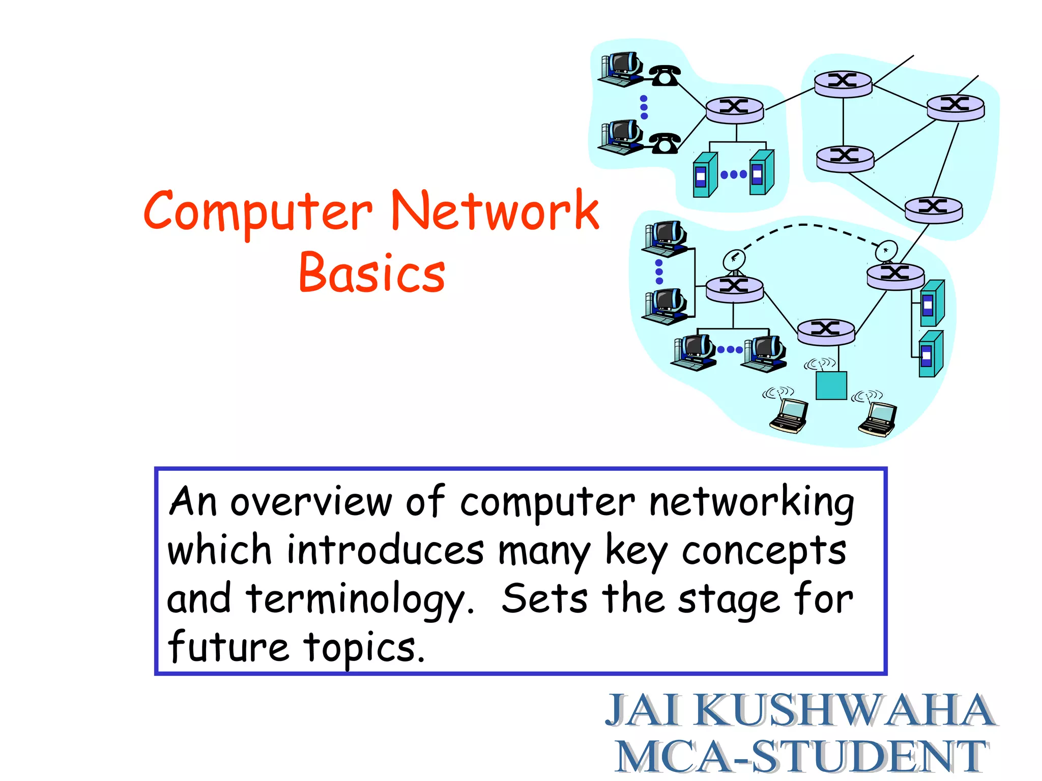
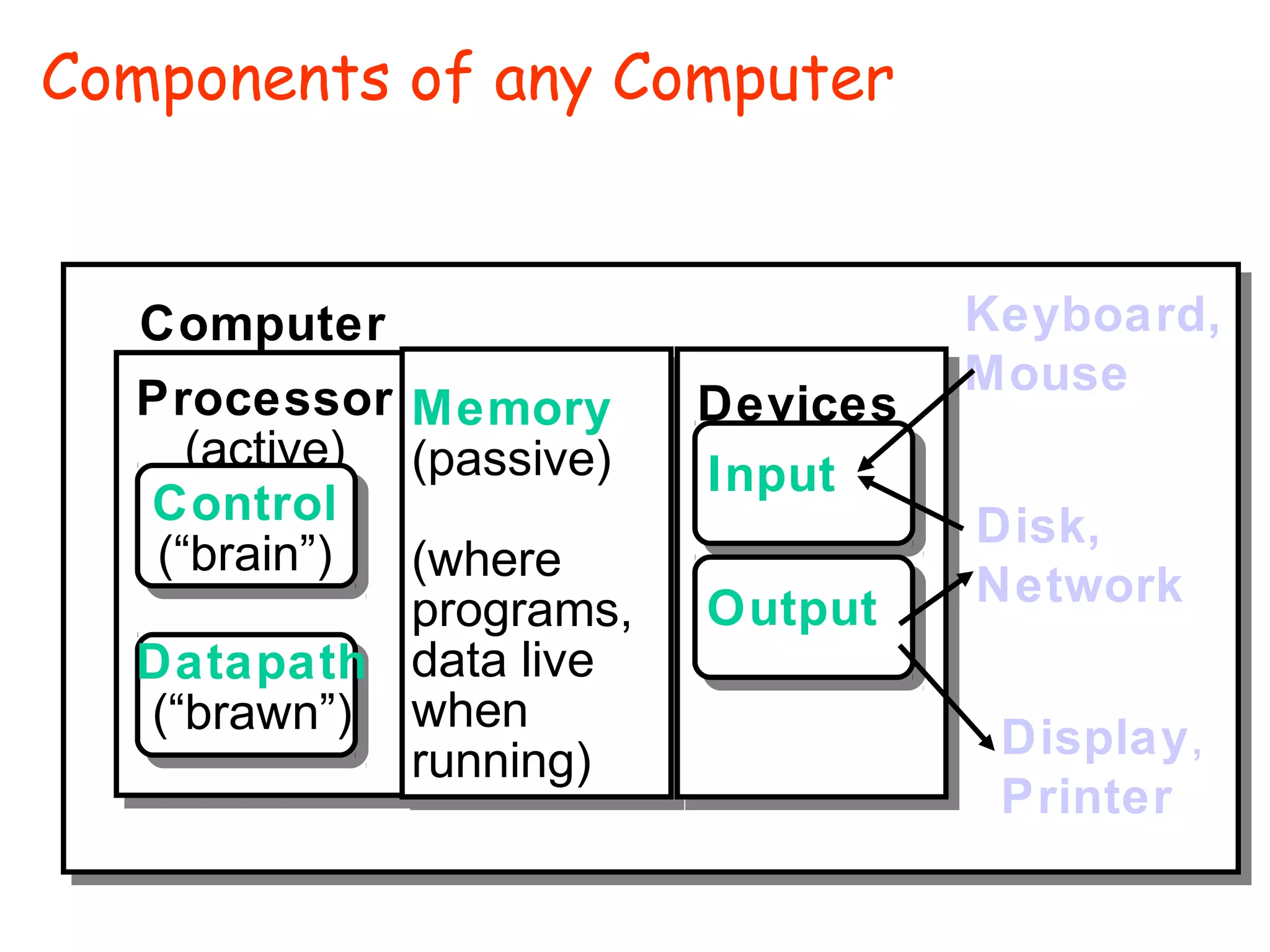
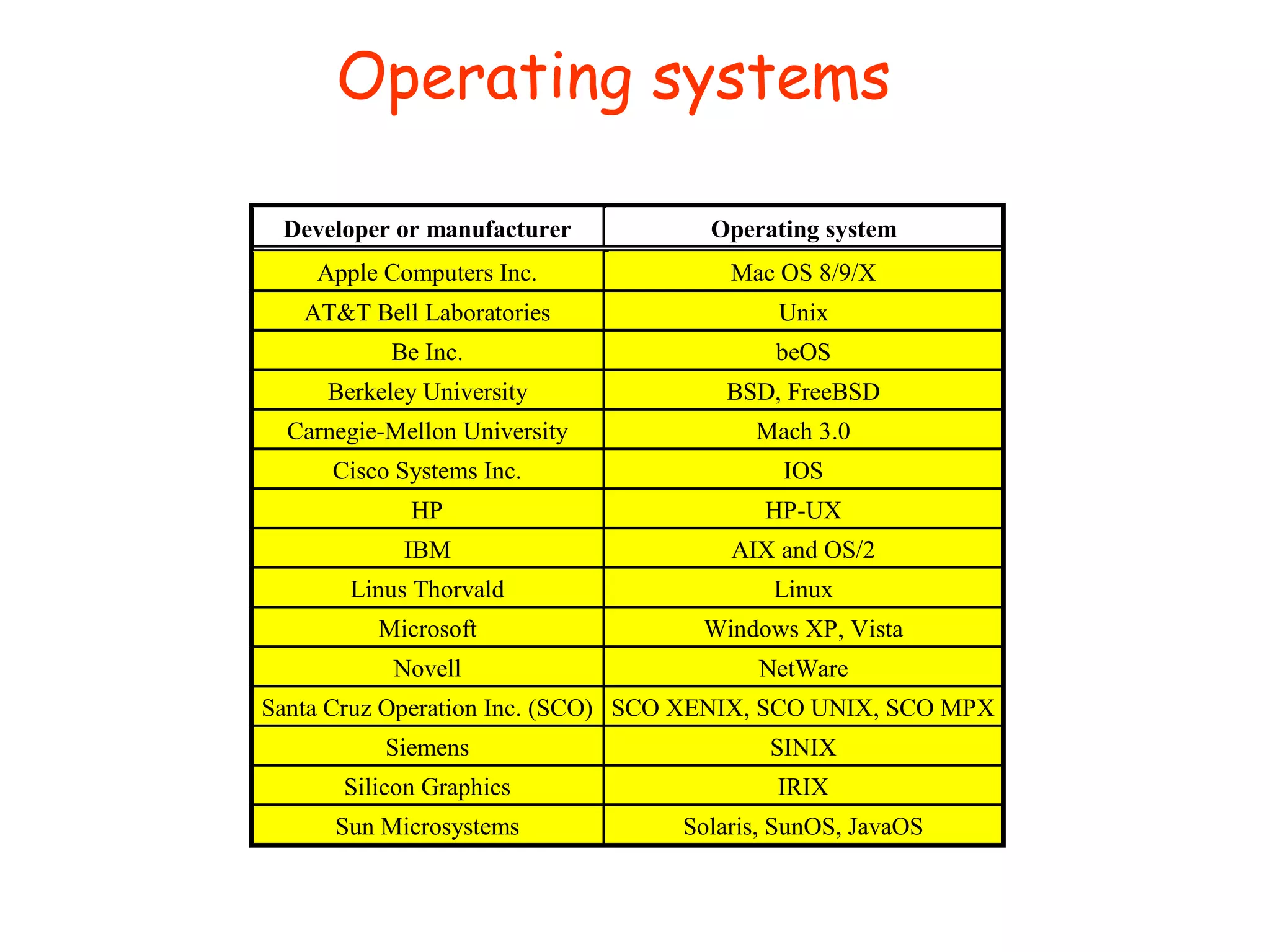
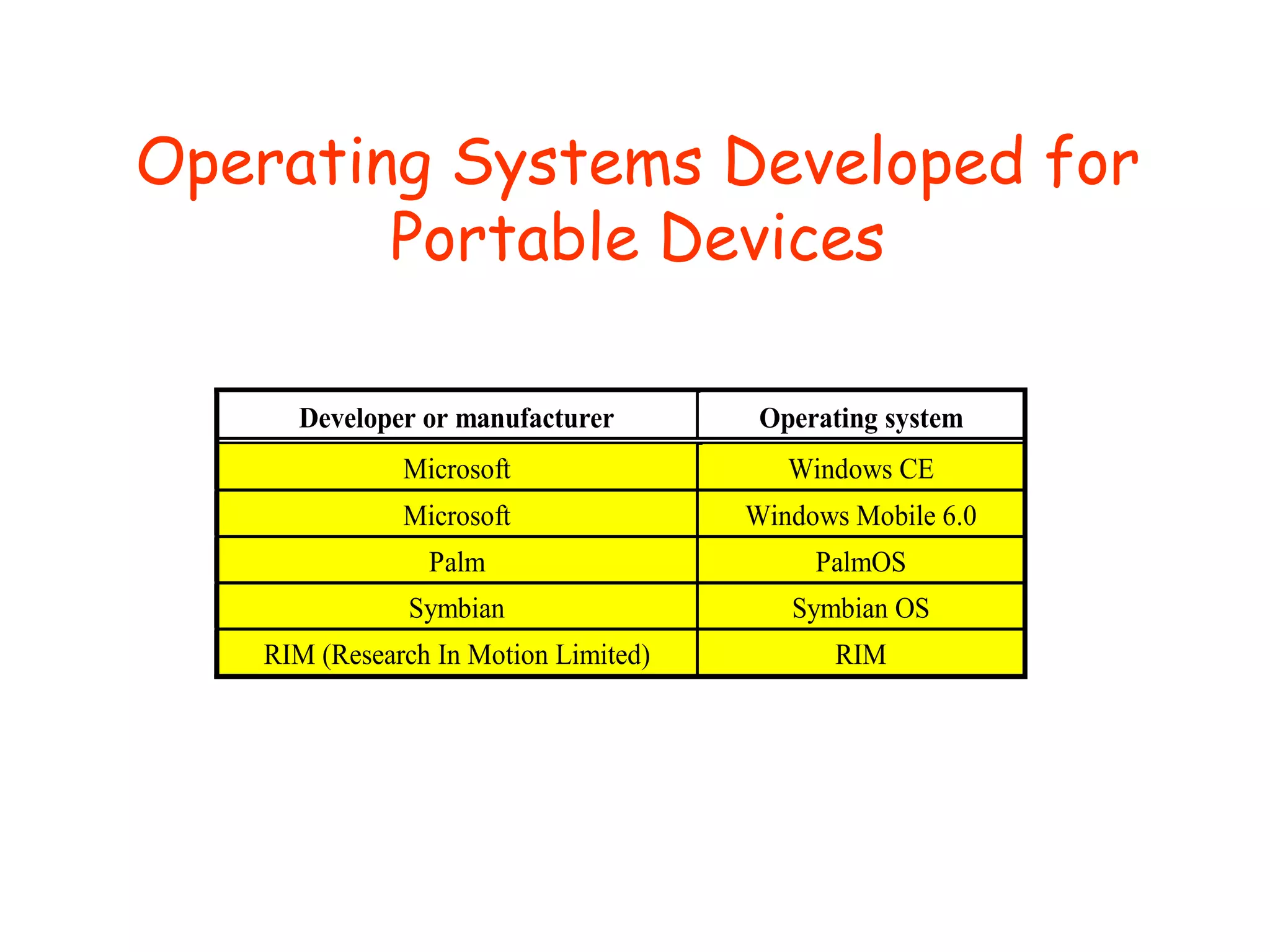
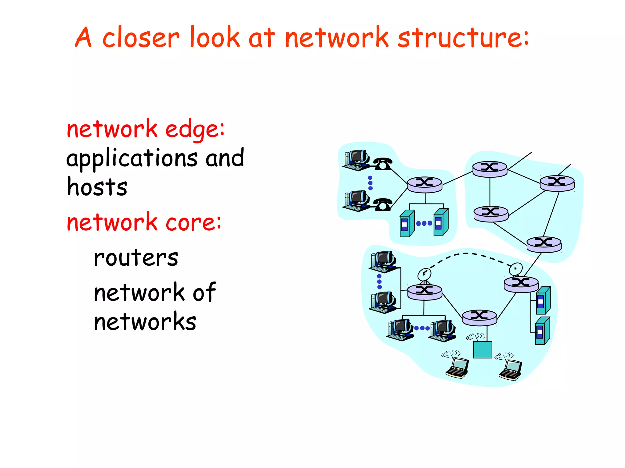
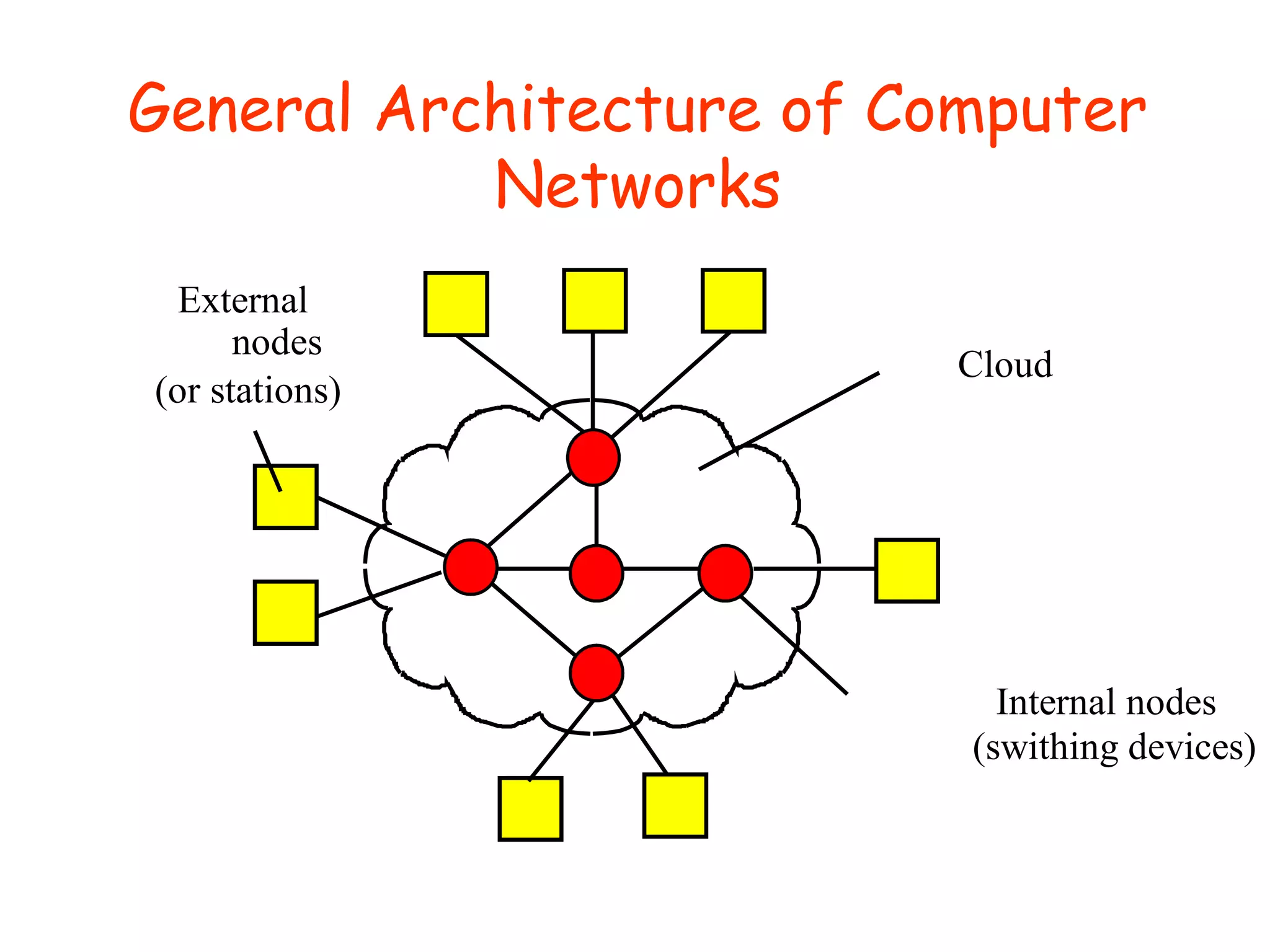
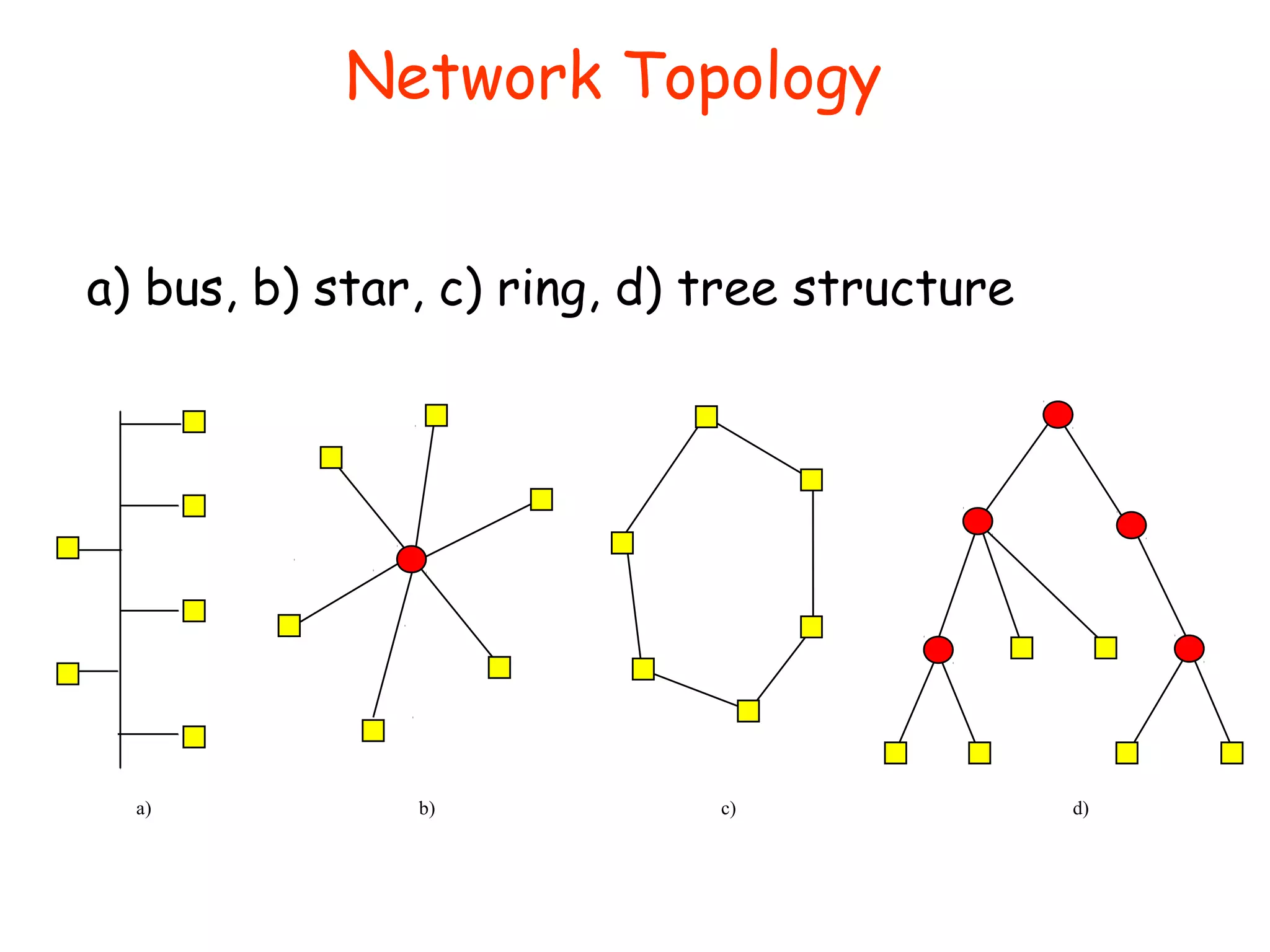
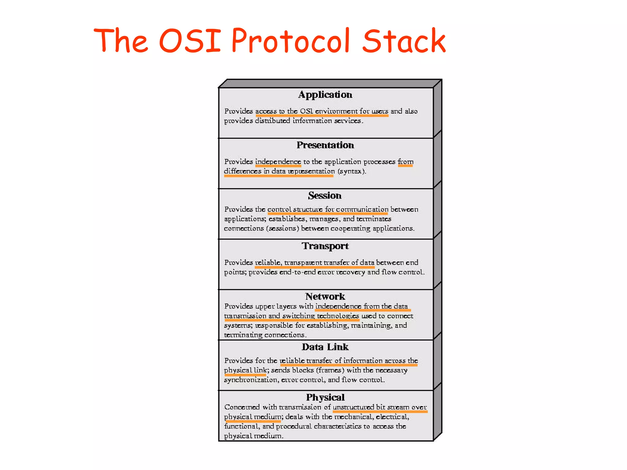
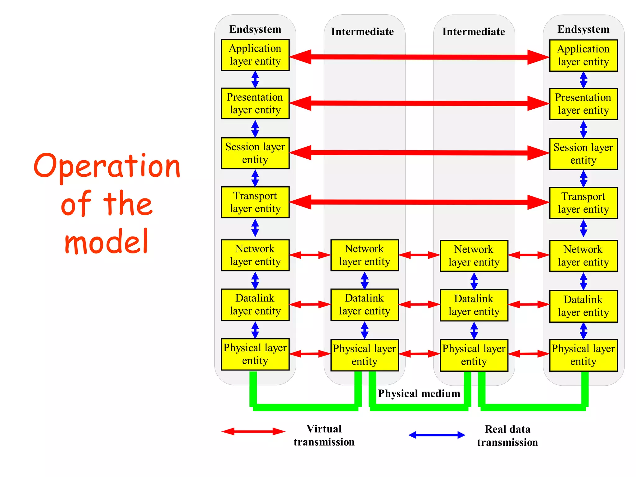
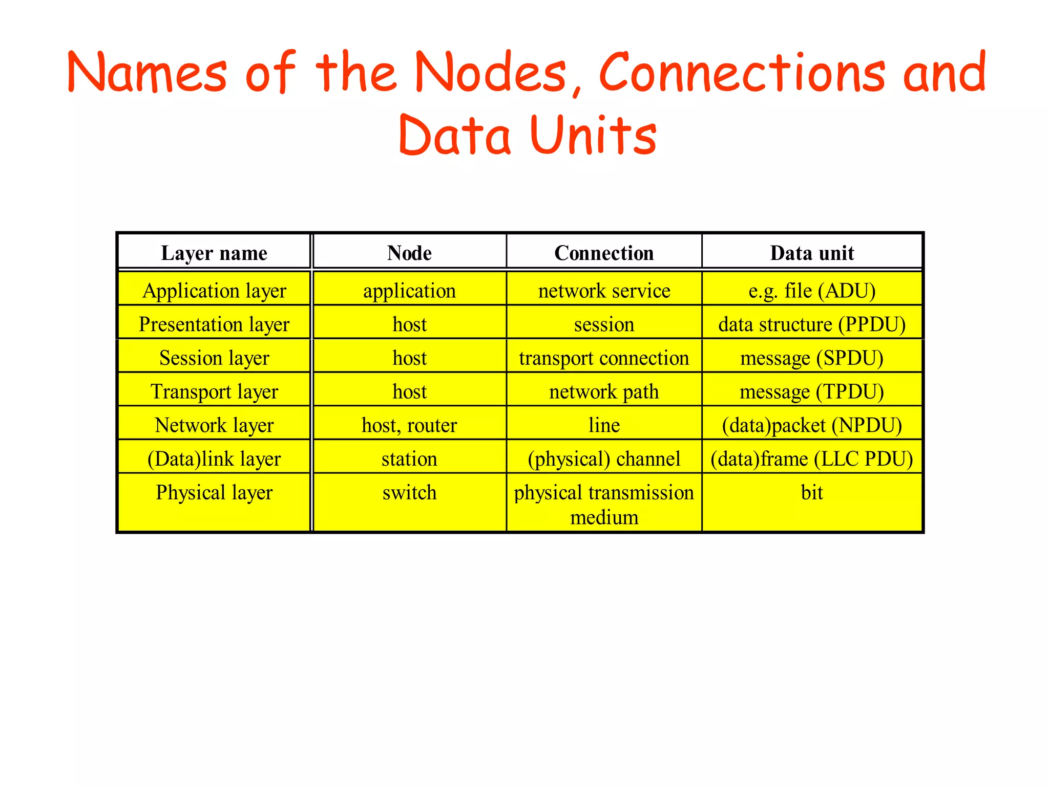
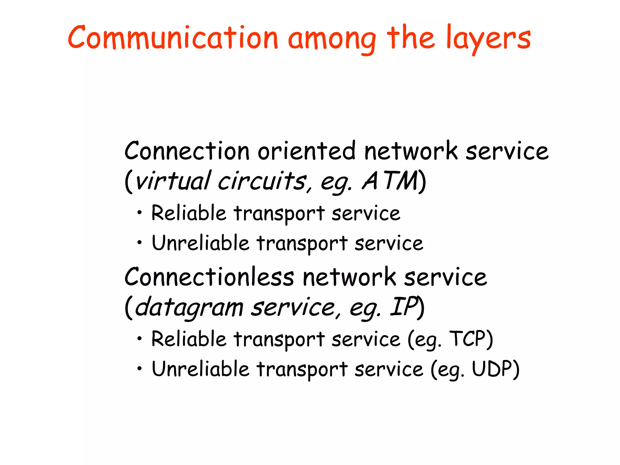
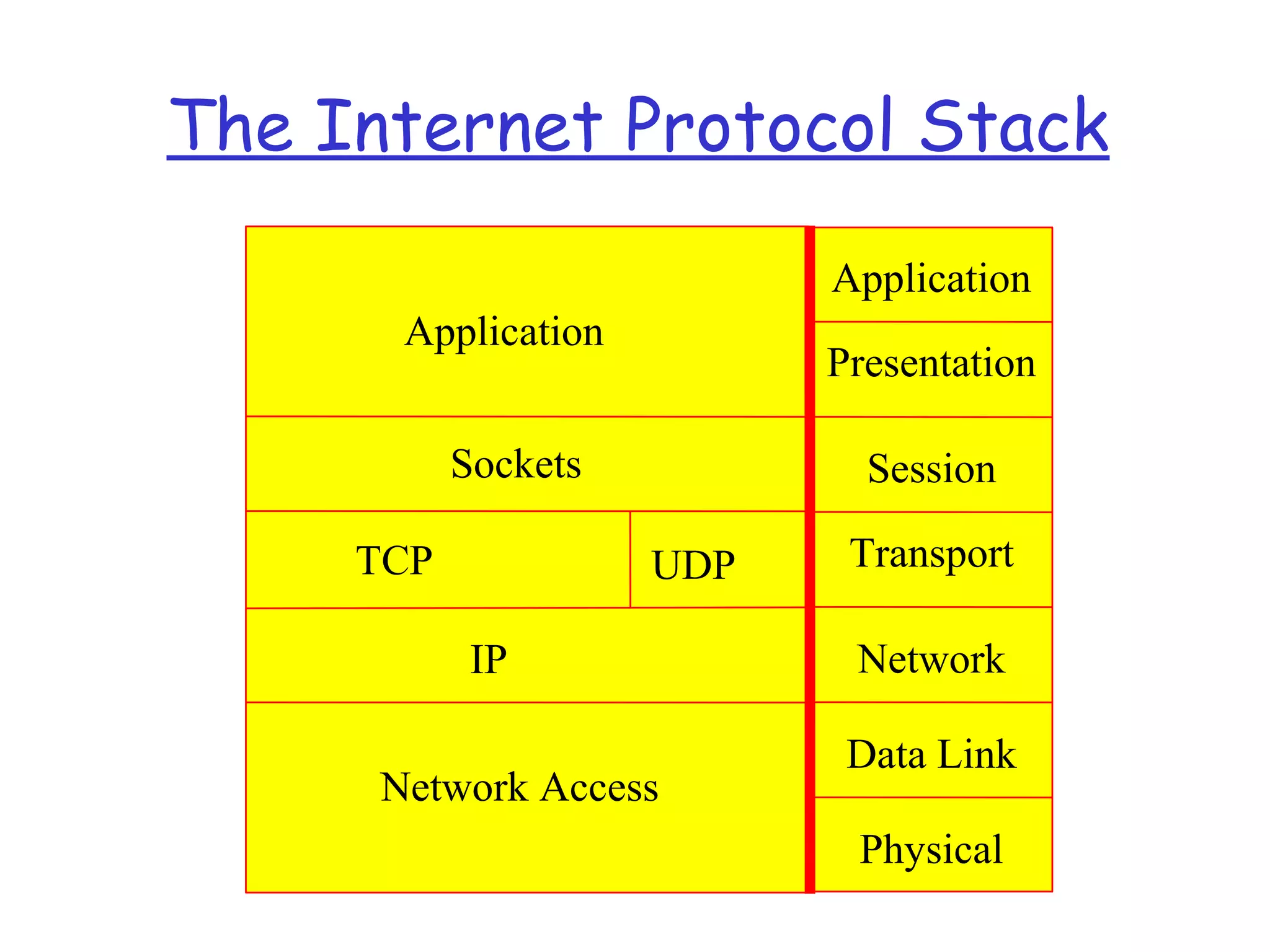
This document provides an overview of computer networking concepts and terminology. It introduces the key components of a computer including the processor, memory, and input/output devices. It also covers communication devices and how they can be synchronous or asynchronous. The document discusses how networks are connected including different types of buses and hierarchies. It provides an overview of different operating systems from various developers. It also covers network structure, topologies, media, reliability, flow control, congestion, and the layered protocol architecture of the OSI model.


![SHS_Core_CAE_Q3_LE1 FOR THIRD [FINAL].pdf](https://cdn.slidesharecdn.com/ss_thumbnails/shscorecaeq3le1final-251116055110-e3081055-thumbnail.jpg?width=640&height=640&fit=bounds)

