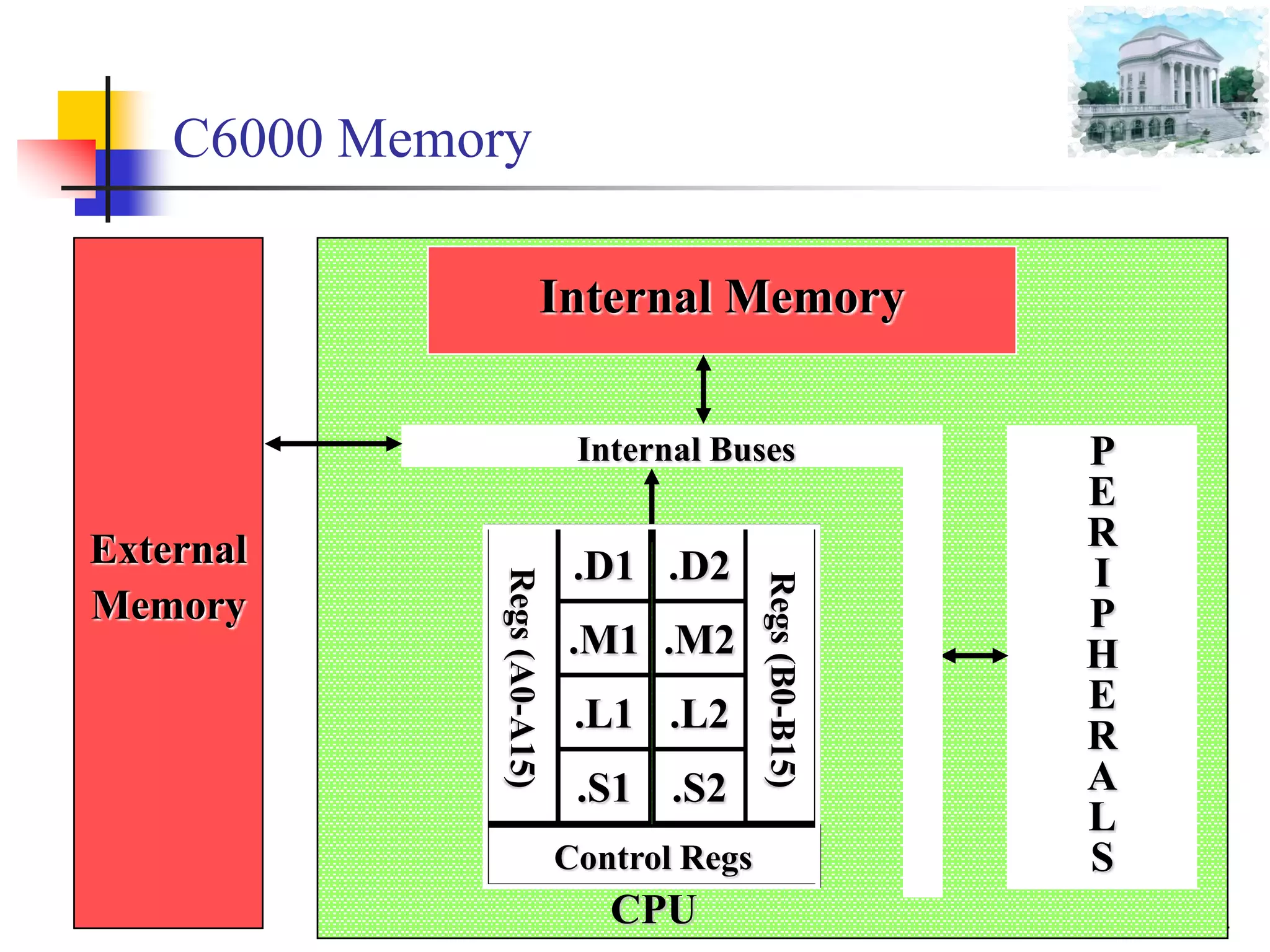
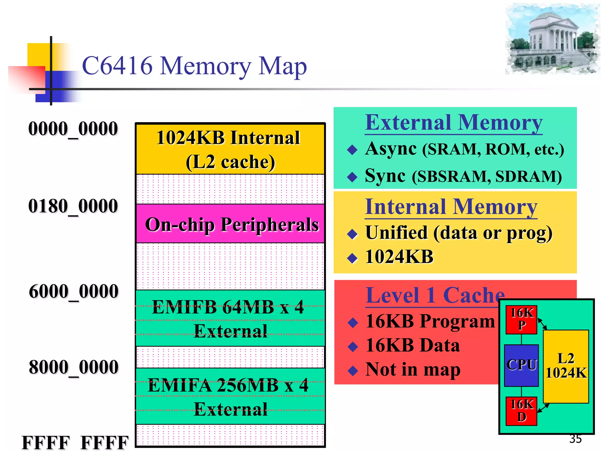
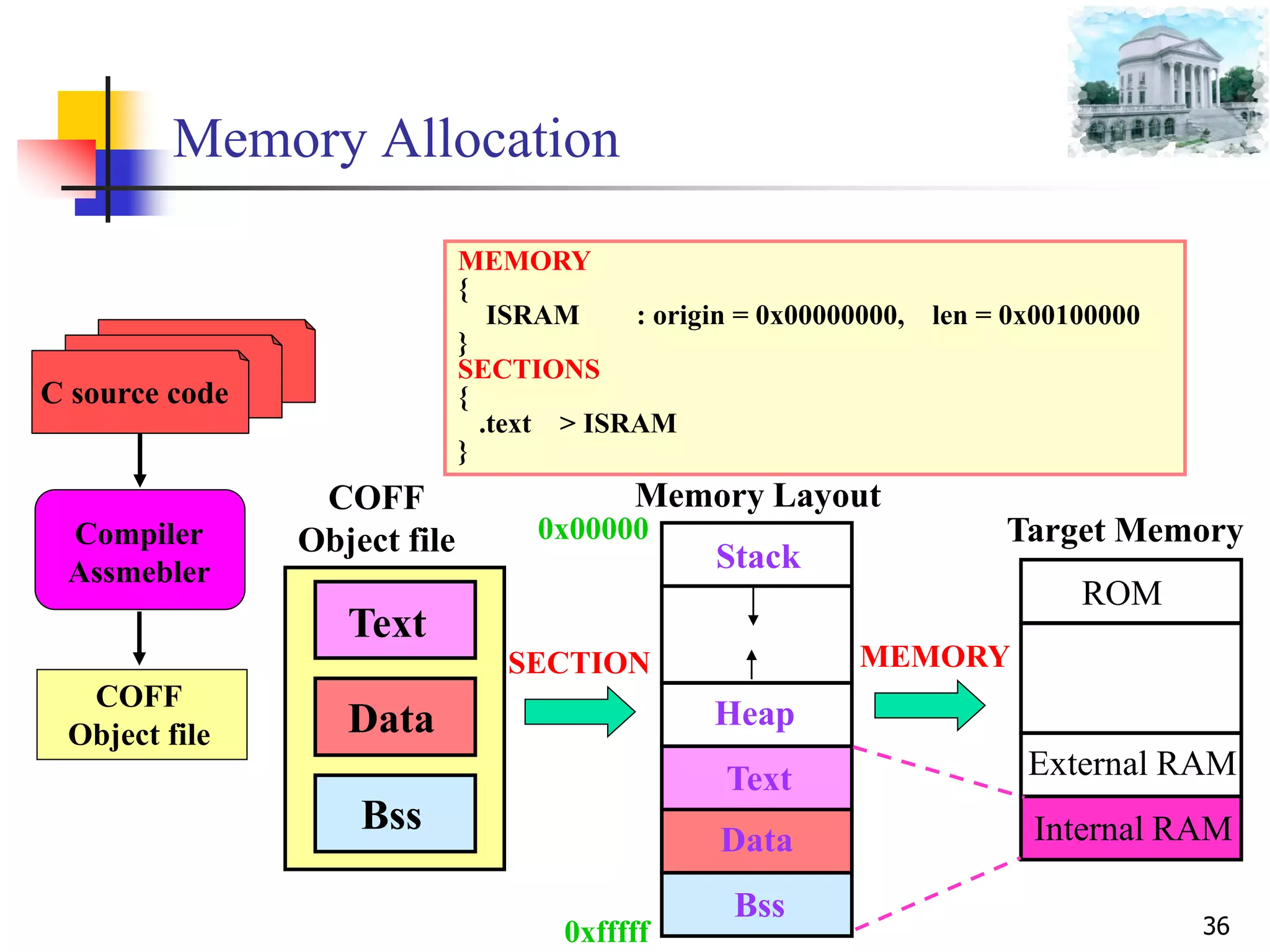
The document provides an introduction to DSP processors and the Texas Instruments C6000 architecture, outlining key components like the CPU, register files, and peripheral units used for multiplication, addition, loading, storing, and branching. It describes the C6000 memory map and organization, including internal memory, external memory interfaces, and how code and data are allocated in memory sections.

![8
Why do we need DSP processors?
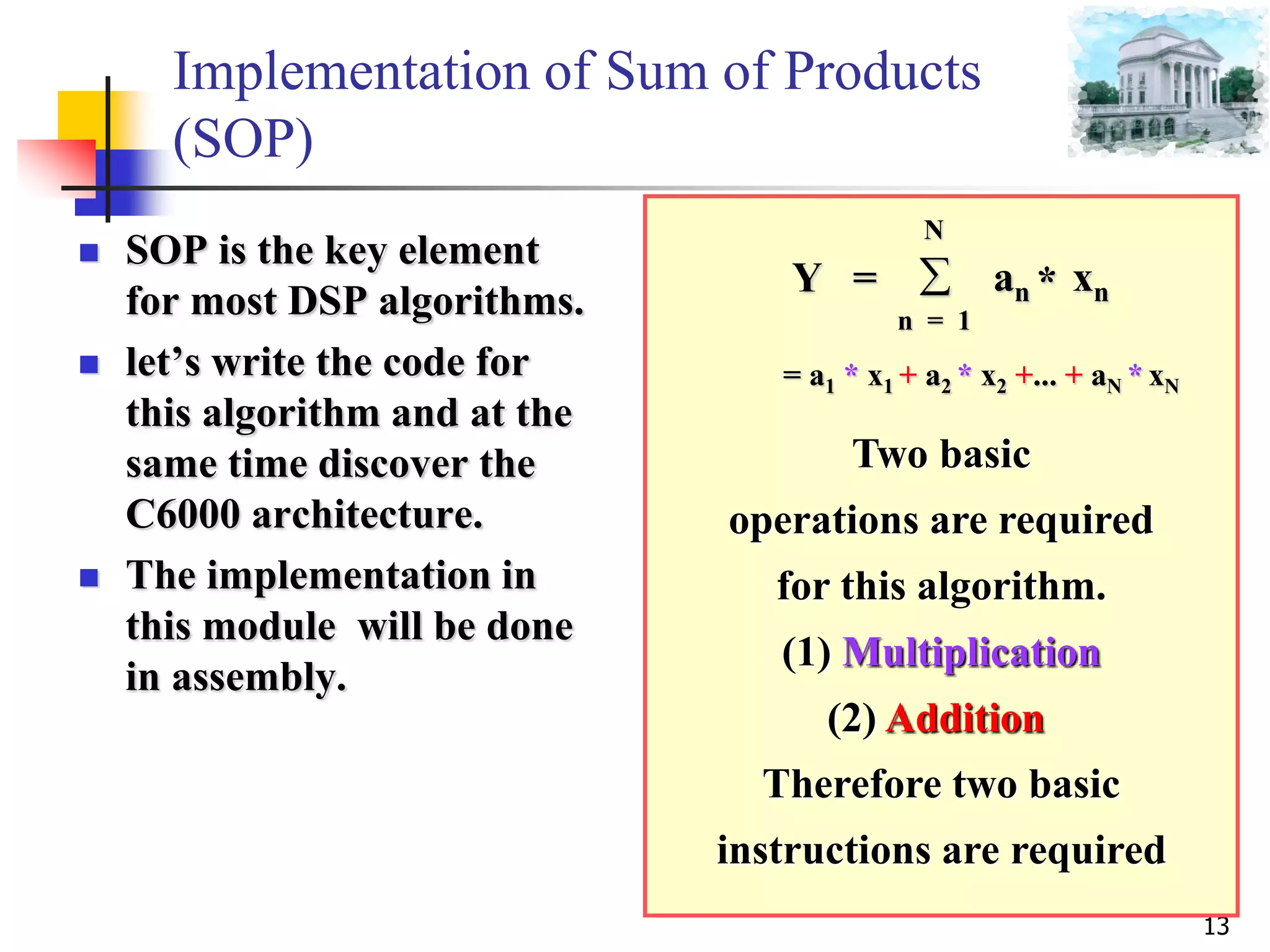
The Sum of Products (SOP) or Multiply-
accumulate(MAC) is the key element in most DSP
algorithms:Algorithm Equation
Finite Impulse Response Filter
M
k
k knxany
0
)()(
Infinite Impulse Response Filter
N
k
k
M
k
k knybknxany
10
)()()(
Convolution
N
k
knhkxny
0
)()()(
Discrete Fourier Transform
1
0
])/2(exp[)()(
N
n
nkNjnxkX
Discrete Cosine Transform
1
0
12
2
cos).().(
N
x
xu
N
xfucuF
](https://image.slidesharecdn.com/1introductiontodspprocessor20140919-150518014745-lva1-app6891/75/1-introduction-to-dsp-processor-20140919-8-2048.jpg)
![39
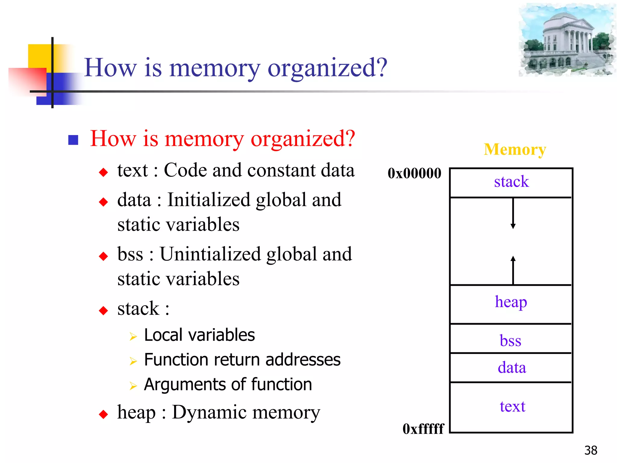
How is memory allocated?
How is memory allocated ?
long array[100];
long bufsize =100;
int main(void) {
int i;
char* buf;
i=10;
buf=f1(i);
return(0);
}
Char* f1(int n){
int k;
Return malloc(bufsize);
}
Memory
0x00000
0xfffff
heap
bss
data
text
stack
100 byte block
array[100]
bufsize = 100
int main(void) {
i=10;
buf=f1(i);
return(0);
} …
Main return address
i
buf
f1 argument n
f1 return address
k](https://image.slidesharecdn.com/1introductiontodspprocessor20140919-150518014745-lva1-app6891/75/1-introduction-to-dsp-processor-20140919-39-2048.jpg)
![41
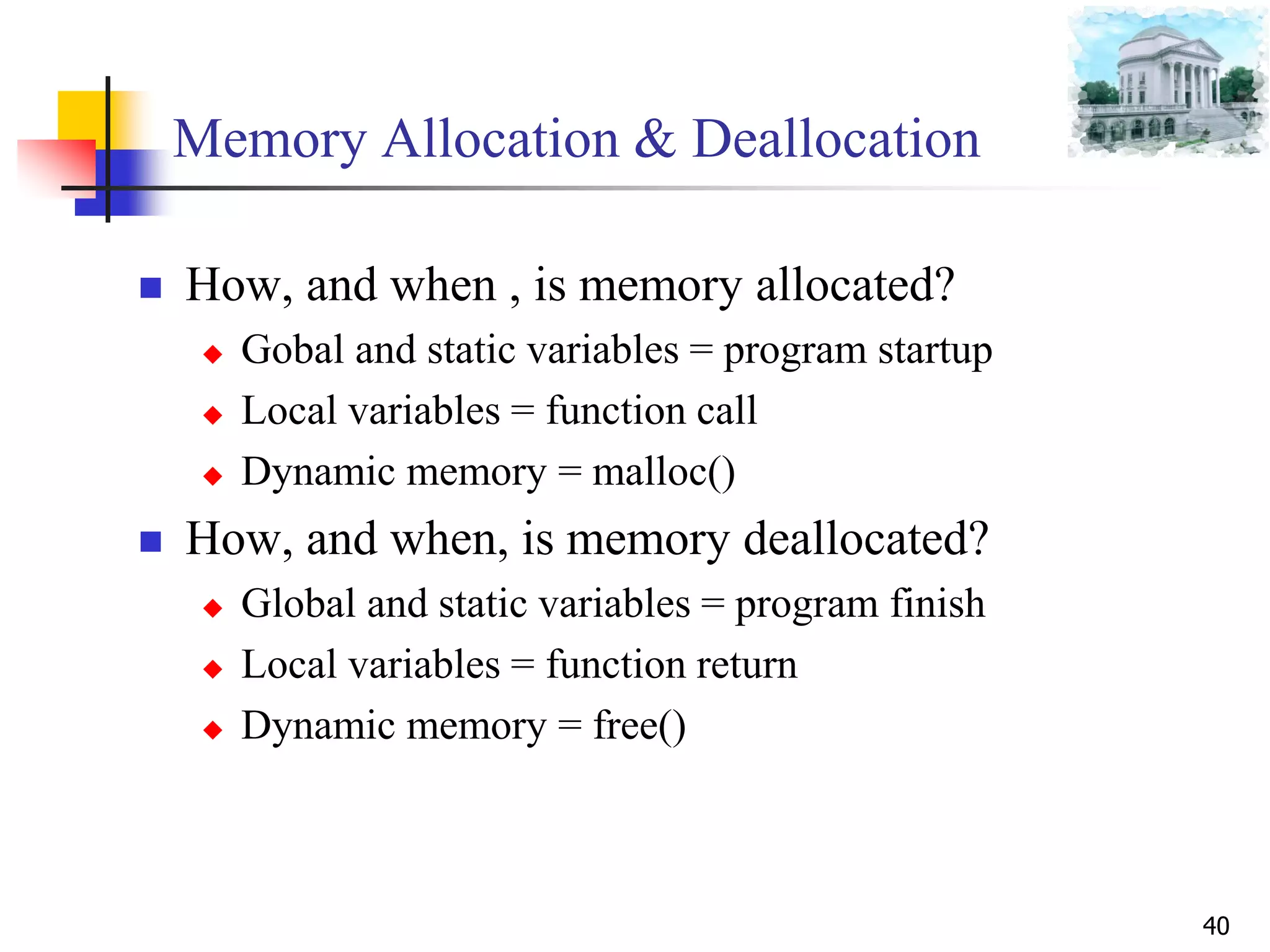
When is memory allocated?
long array[100];
long bufsize =100;
int main(void) {
int i;
char* buf;
i=10;
buf=f1(i);
return(0);
}
Char* f1(int n){
int k;
Return malloc(bufsize);
}
bss : 0 at startup
data : 100 at startup
Stack : at function call
Stack : at function call
Heap : 100 bytes at malloc()](https://image.slidesharecdn.com/1introductiontodspprocessor20140919-150518014745-lva1-app6891/75/1-introduction-to-dsp-processor-20140919-41-2048.jpg)
![42
When is memory deallocated?
long array[100];
long bufsize =100;
int main(void) {
int i;
char* buf;
i=10;
buf=f1(i);
return(0);
}
Char* f1(int n){
int k;
Return malloc(bufsize);
}
Available till termination
Available till termination
Deallocate on return from main()
Deallocate on return from f1()
Deallocate on free()](https://image.slidesharecdn.com/1introductiontodspprocessor20140919-150518014745-lva1-app6891/75/1-introduction-to-dsp-processor-20140919-42-2048.jpg)
![Program Cases :
Case 1 :
51
Void main()
{
int Image[1000];
….
}
int Image[1000];
Void main()
{
….
}
stack = ?
stack 0x400 (1024)](https://image.slidesharecdn.com/1introductiontodspprocessor20140919-150518014745-lva1-app6891/75/1-introduction-to-dsp-processor-20140919-51-2048.jpg)
![Program Cases :
Case 2 :
52
Void main()
{
double Image[200000];
….
}
52
bss > SDRAM
stack 0x400 (1024)
bss < 0x100000 (1024k)
double Image[200000];
Void main()
{
….
}](https://image.slidesharecdn.com/1introductiontodspprocessor20140919-150518014745-lva1-app6891/75/1-introduction-to-dsp-processor-20140919-52-2048.jpg)


![8
Why do we need DSP processors?
The Sum of Products (SOP) or Multiply-
accumulate(MAC) is the key element in most DSP
algorithms:Algorithm Equation
Finite Impulse Response Filter
M
k
k knxany
0
)()(
Infinite Impulse Response Filter
N
k
k
M
k
k knybknxany
10
)()()(
Convolution
N
k
knhkxny
0
)()()(
Discrete Fourier Transform
1
0
])/2(exp[)()(
N
n
nkNjnxkX
Discrete Cosine Transform
1
0
12
2
cos).().(
N
x
xu
N
xfucuF
](https://crownmelresort.com/image.slidesharecdn.com/1introductiontodspprocessor20140919-150518014745-lva1-app6891/75/1-introduction-to-dsp-processor-20140919-8-2048.jpg)


![39
How is memory allocated?
How is memory allocated ?
long array[100];
long bufsize =100;
int main(void) {
int i;
char* buf;
i=10;
buf=f1(i);
return(0);
}
Char* f1(int n){
int k;
Return malloc(bufsize);
}
Memory
0x00000
0xfffff
heap
bss
data
text
stack
100 byte block
array[100]
bufsize = 100
int main(void) {
i=10;
buf=f1(i);
return(0);
} …
Main return address
i
buf
f1 argument n
f1 return address
k](https://crownmelresort.com/image.slidesharecdn.com/1introductiontodspprocessor20140919-150518014745-lva1-app6891/75/1-introduction-to-dsp-processor-20140919-39-2048.jpg)

![41
When is memory allocated?
long array[100];
long bufsize =100;
int main(void) {
int i;
char* buf;
i=10;
buf=f1(i);
return(0);
}
Char* f1(int n){
int k;
Return malloc(bufsize);
}
bss : 0 at startup
data : 100 at startup
Stack : at function call
Stack : at function call
Heap : 100 bytes at malloc()](https://crownmelresort.com/image.slidesharecdn.com/1introductiontodspprocessor20140919-150518014745-lva1-app6891/75/1-introduction-to-dsp-processor-20140919-41-2048.jpg)
![42
When is memory deallocated?
long array[100];
long bufsize =100;
int main(void) {
int i;
char* buf;
i=10;
buf=f1(i);
return(0);
}
Char* f1(int n){
int k;
Return malloc(bufsize);
}
Available till termination
Available till termination
Deallocate on return from main()
Deallocate on return from f1()
Deallocate on free()](https://crownmelresort.com/image.slidesharecdn.com/1introductiontodspprocessor20140919-150518014745-lva1-app6891/75/1-introduction-to-dsp-processor-20140919-42-2048.jpg)


![Program Cases :
Case 1 :
51
Void main()
{
int Image[1000];
….
}
int Image[1000];
Void main()
{
….
}
stack = ?
stack 0x400 (1024)](https://crownmelresort.com/image.slidesharecdn.com/1introductiontodspprocessor20140919-150518014745-lva1-app6891/75/1-introduction-to-dsp-processor-20140919-51-2048.jpg)
![Program Cases :
Case 2 :
52
Void main()
{
double Image[200000];
….
}
52
bss > SDRAM
stack 0x400 (1024)
bss < 0x100000 (1024k)
double Image[200000];
Void main()
{
….
}](https://crownmelresort.com/image.slidesharecdn.com/1introductiontodspprocessor20140919-150518014745-lva1-app6891/75/1-introduction-to-dsp-processor-20140919-52-2048.jpg)