Downloaded 1,788 times
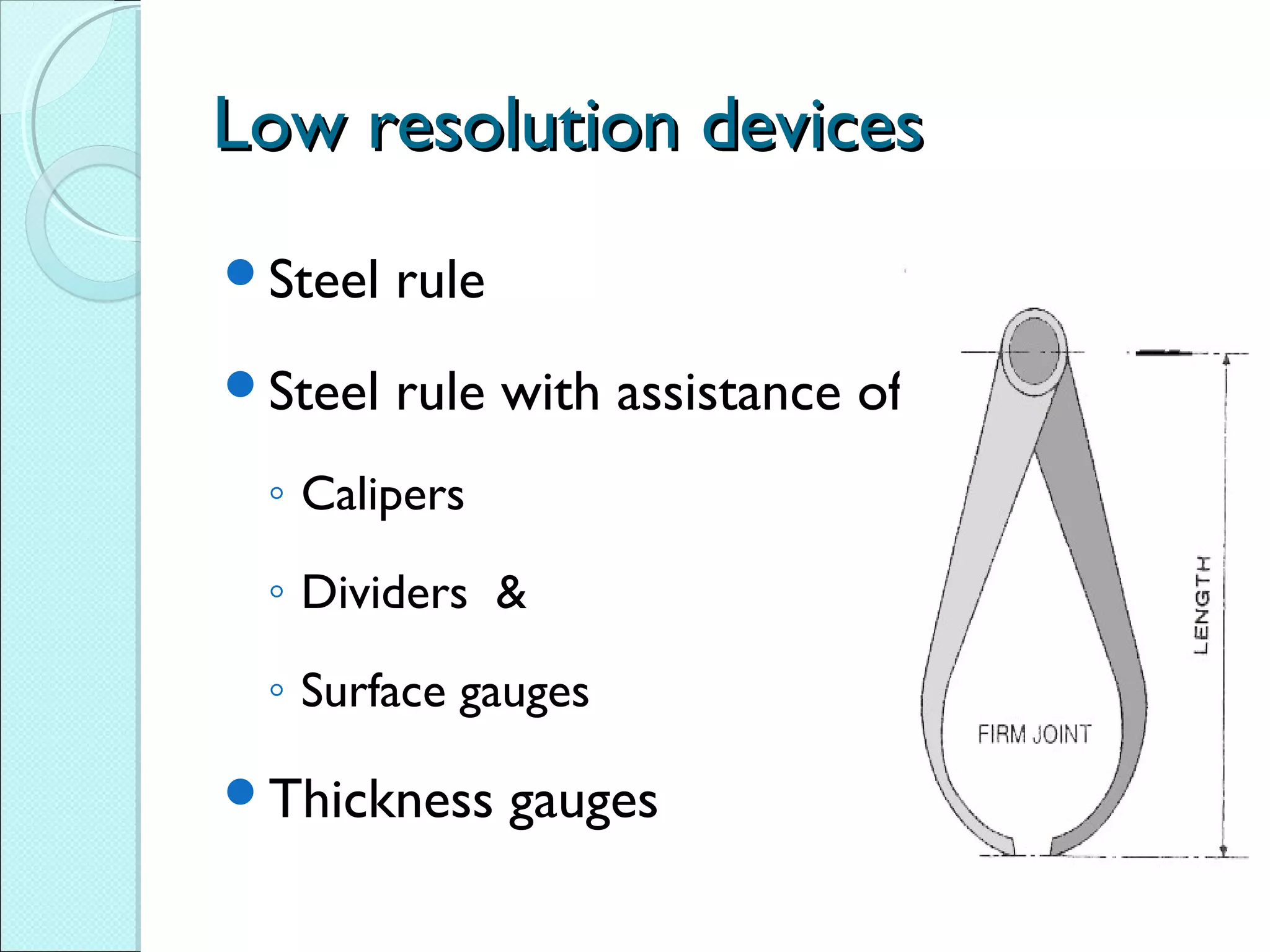
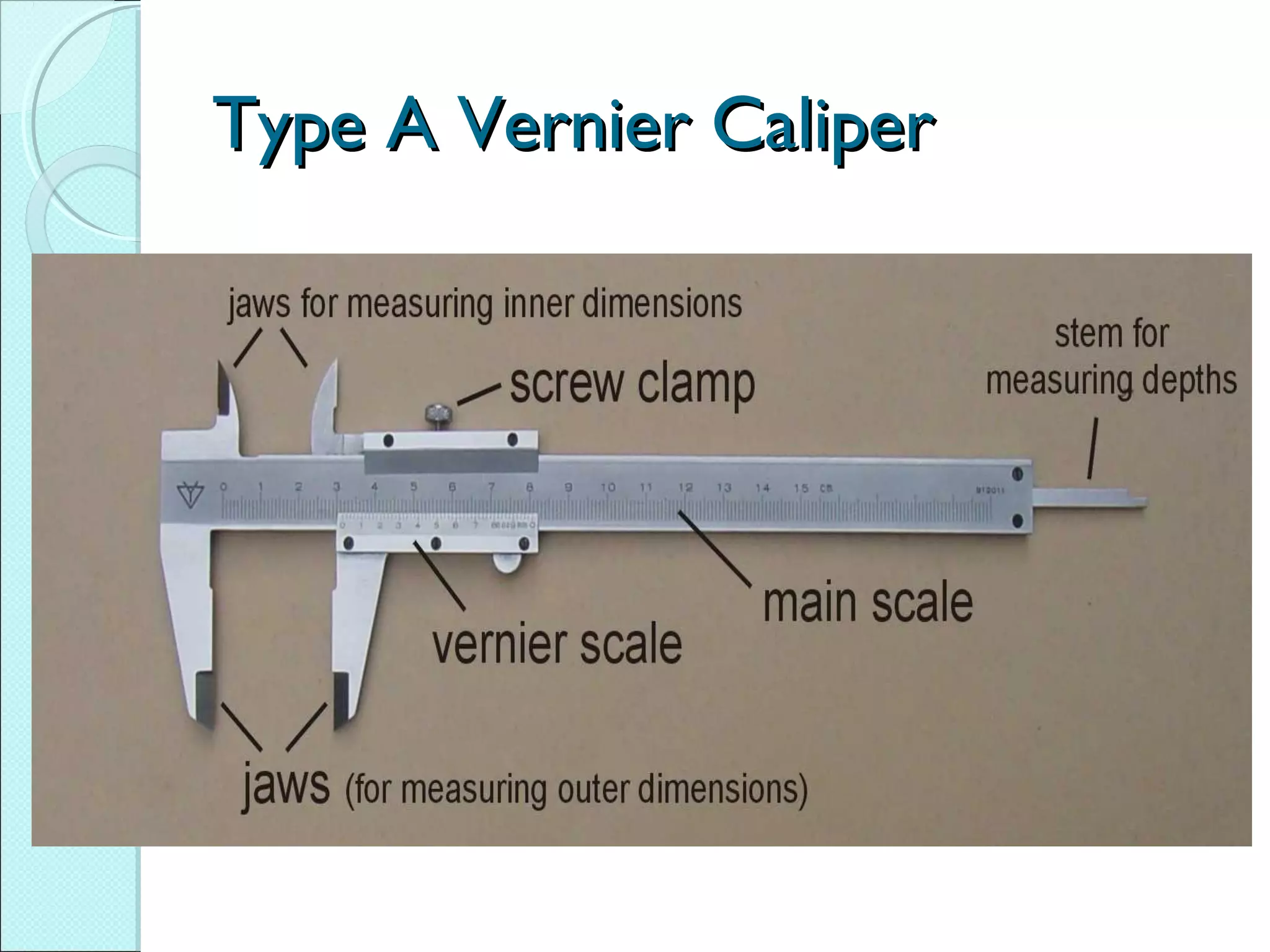
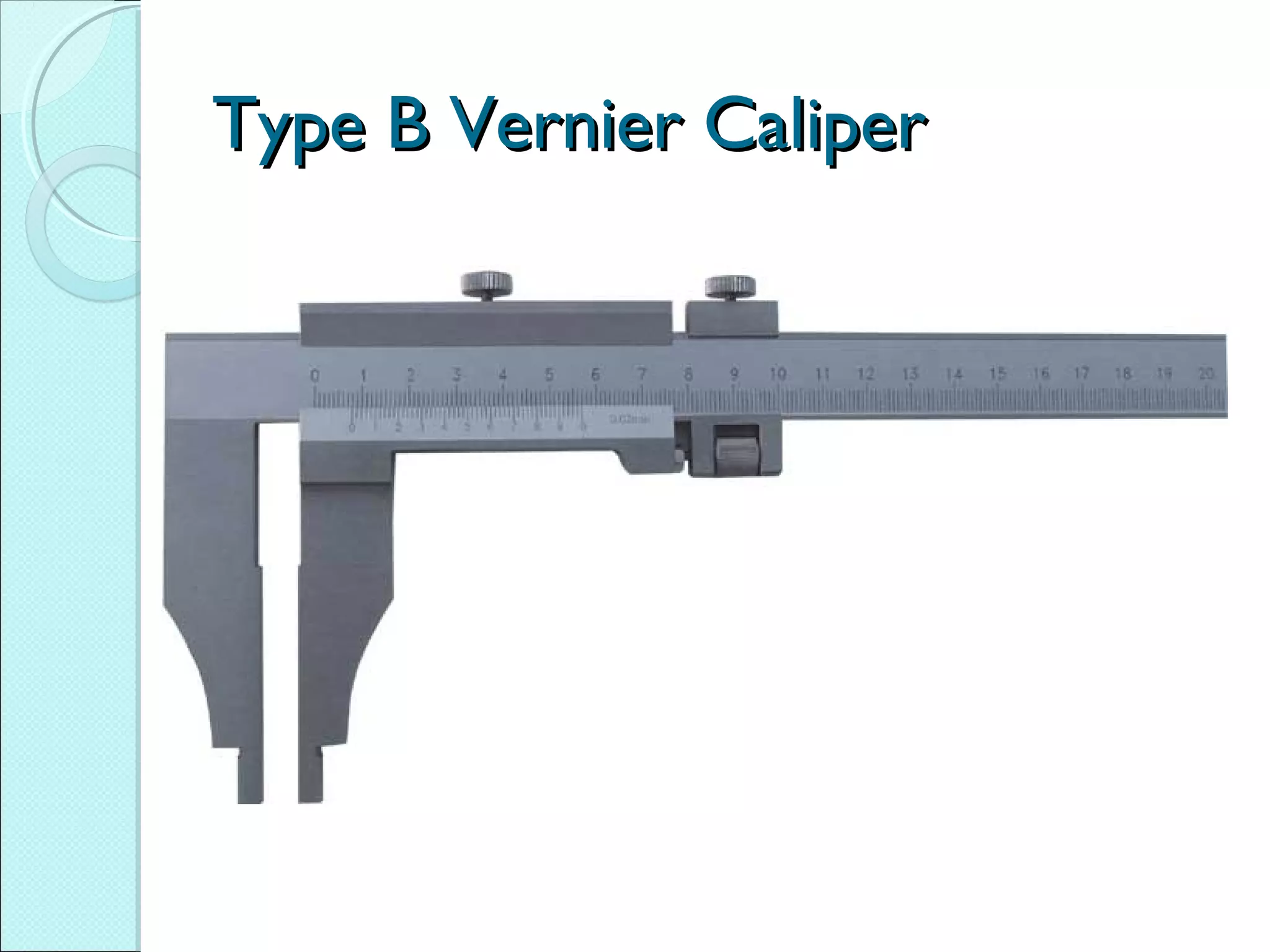
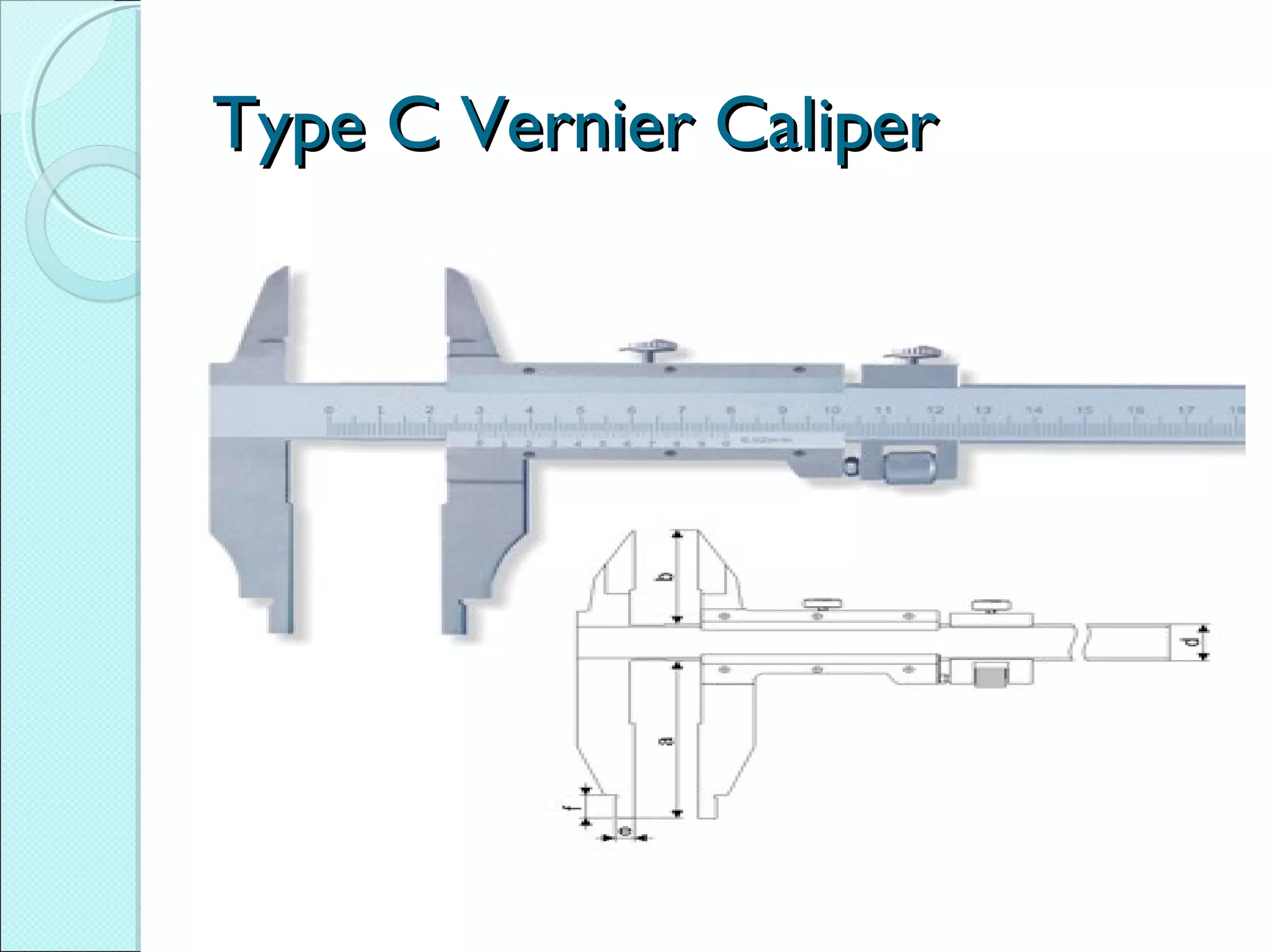
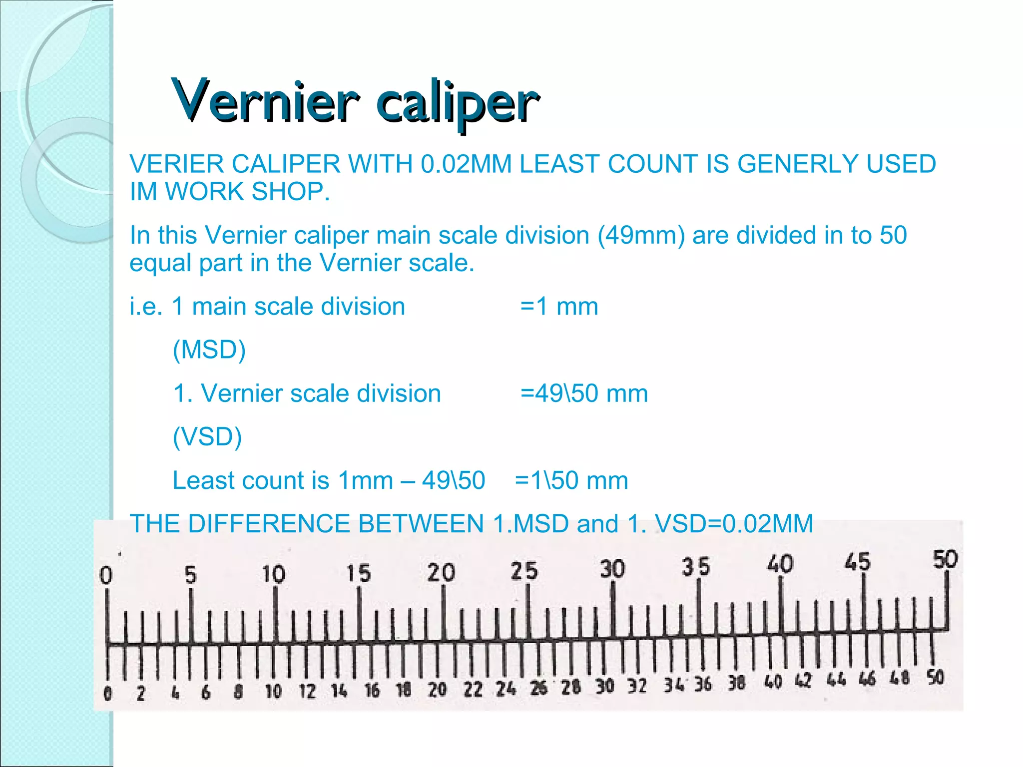
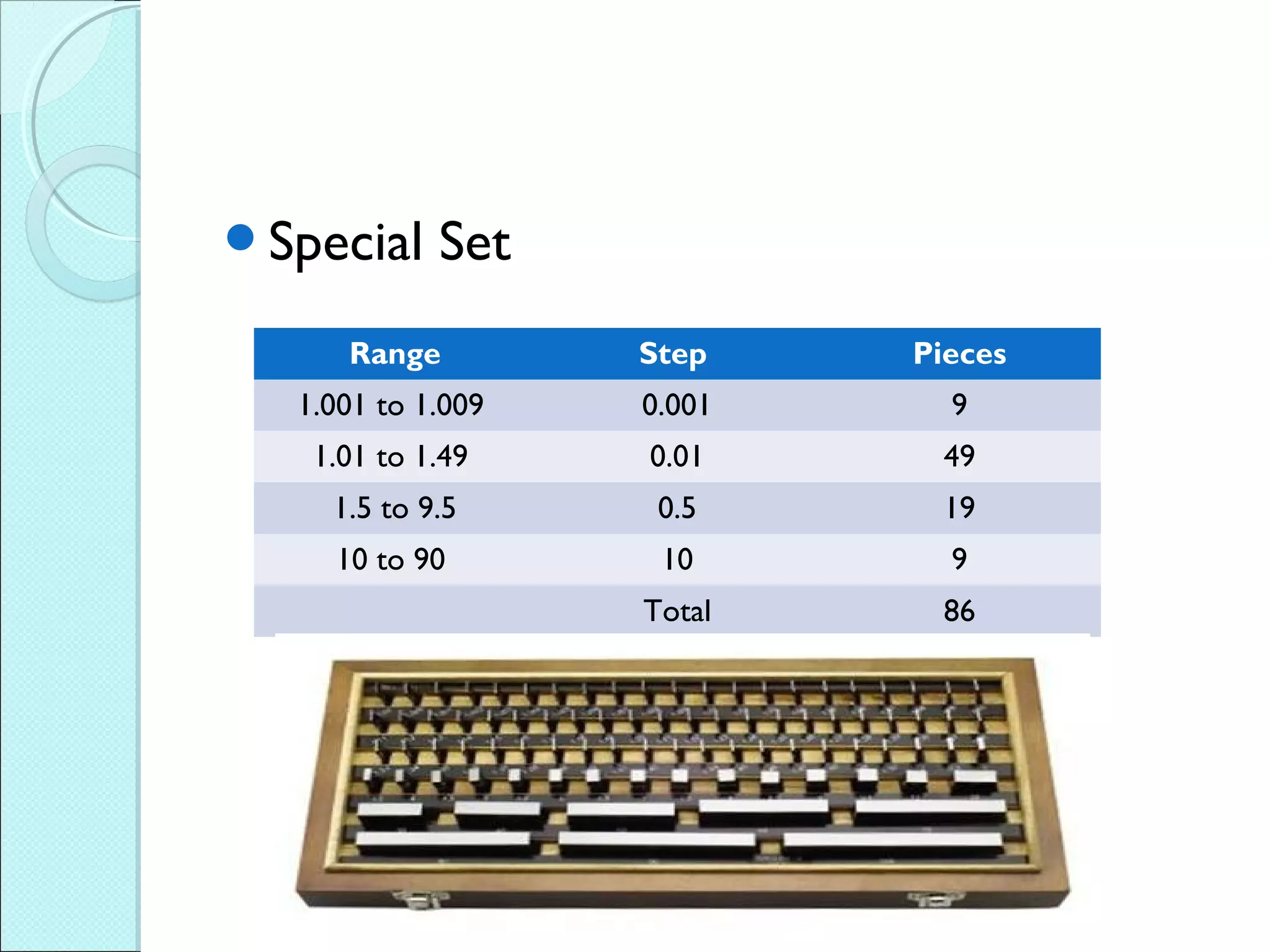
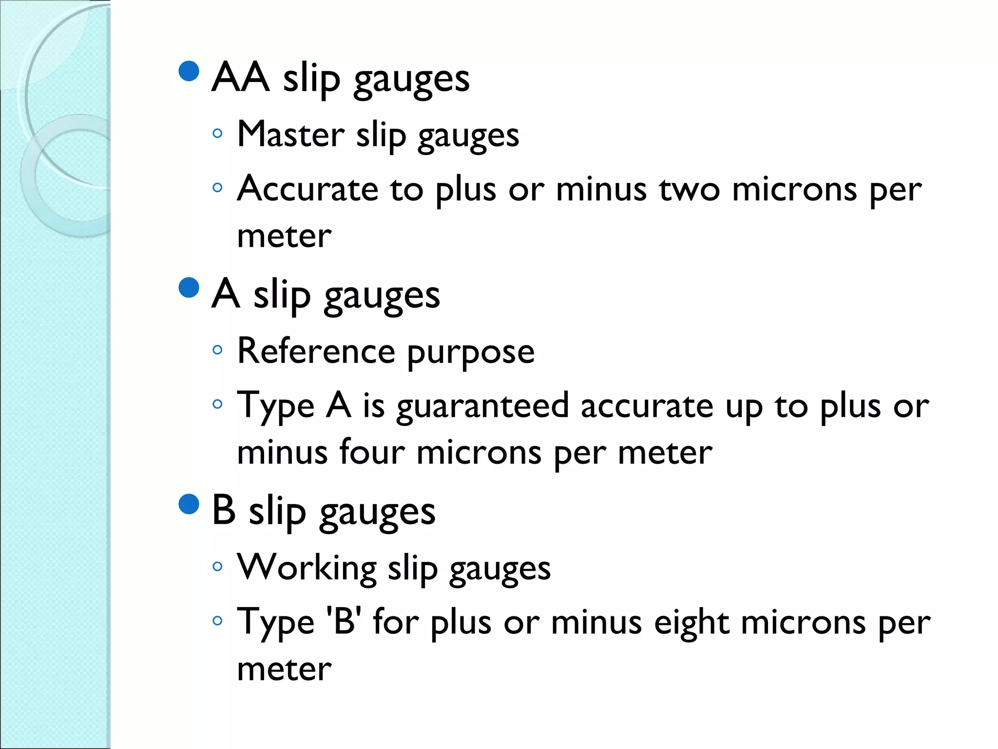
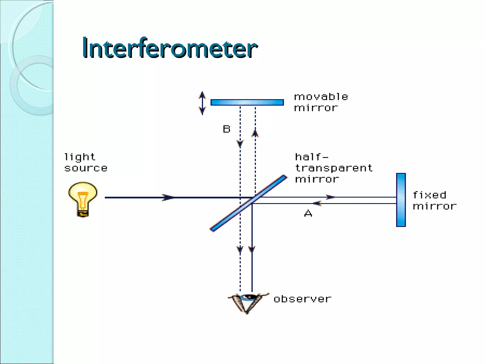
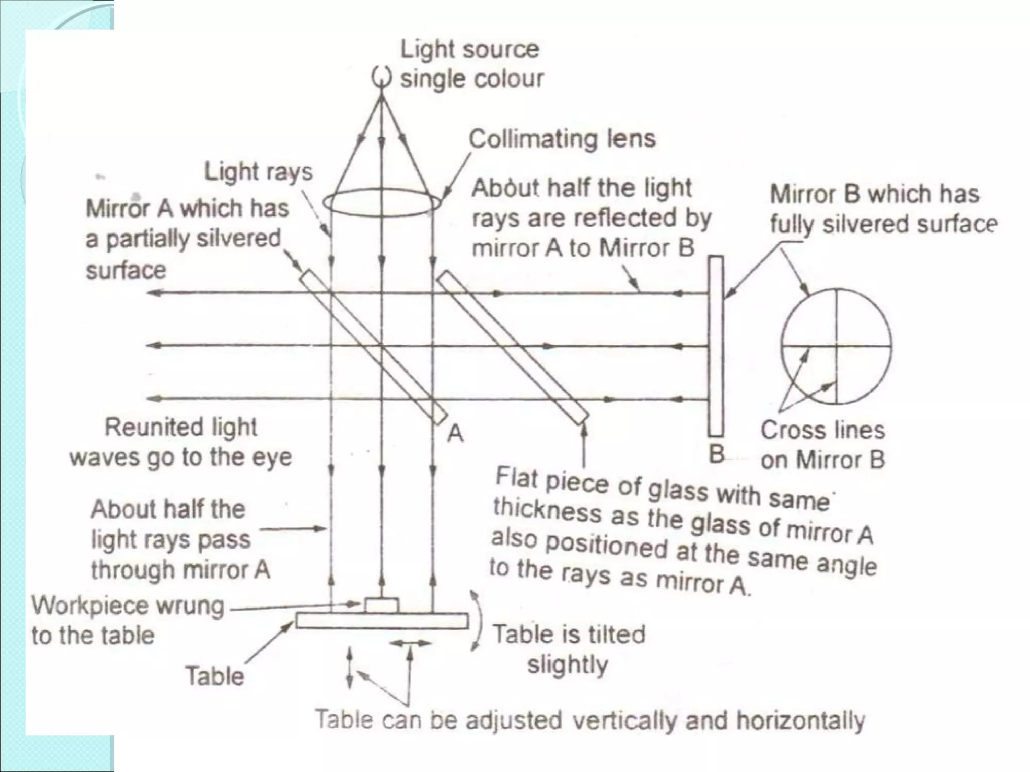
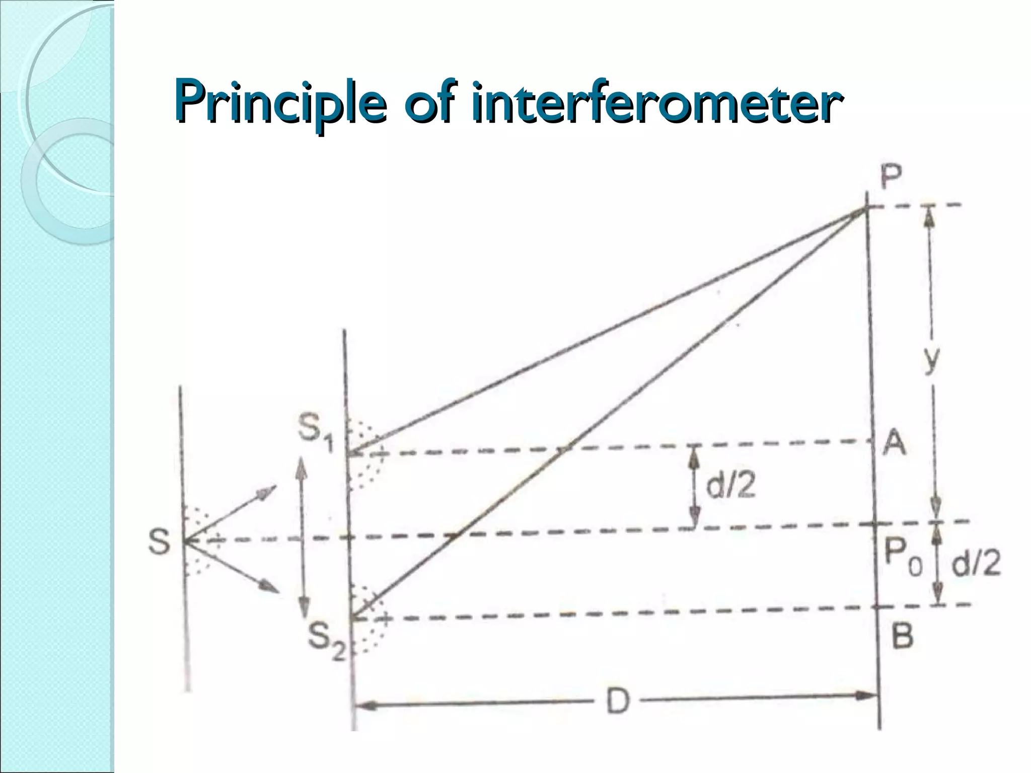
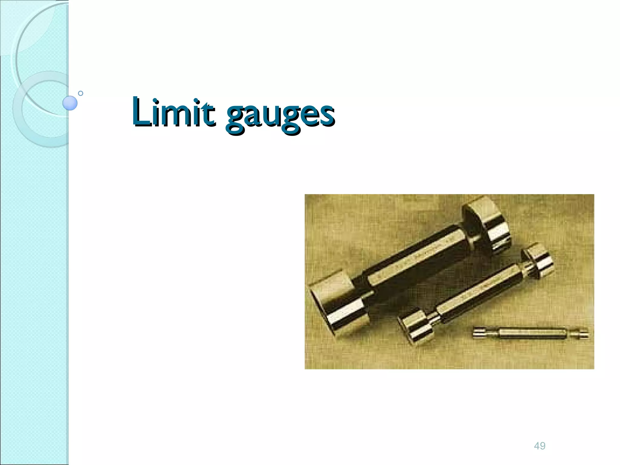
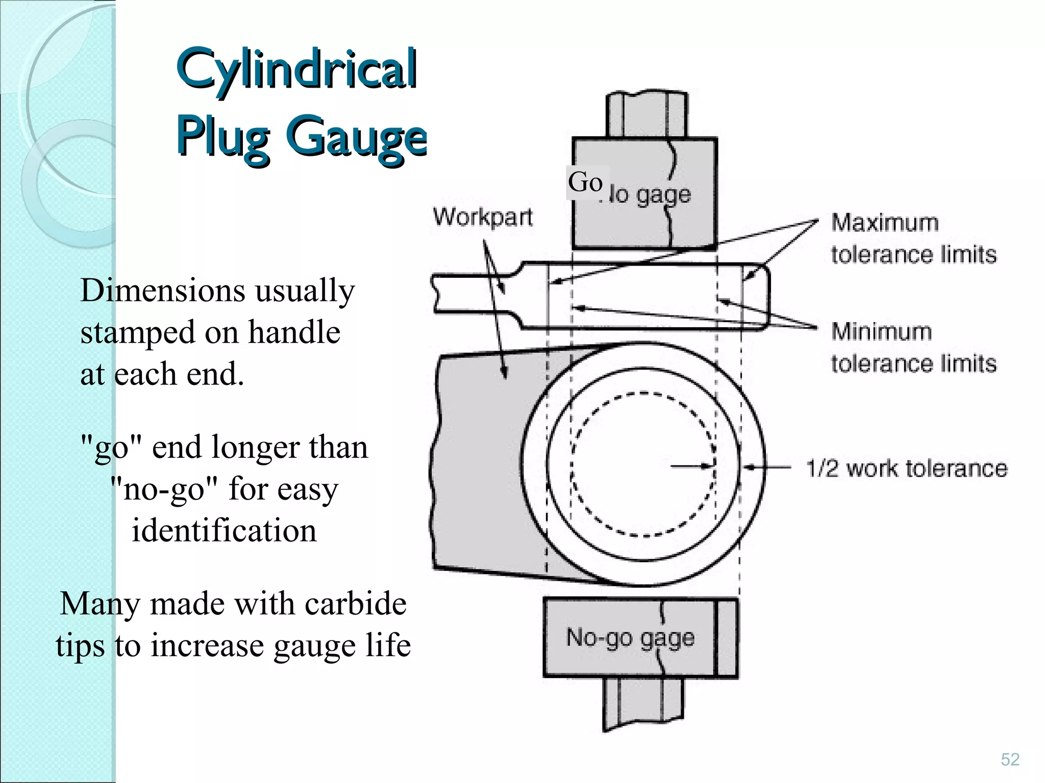
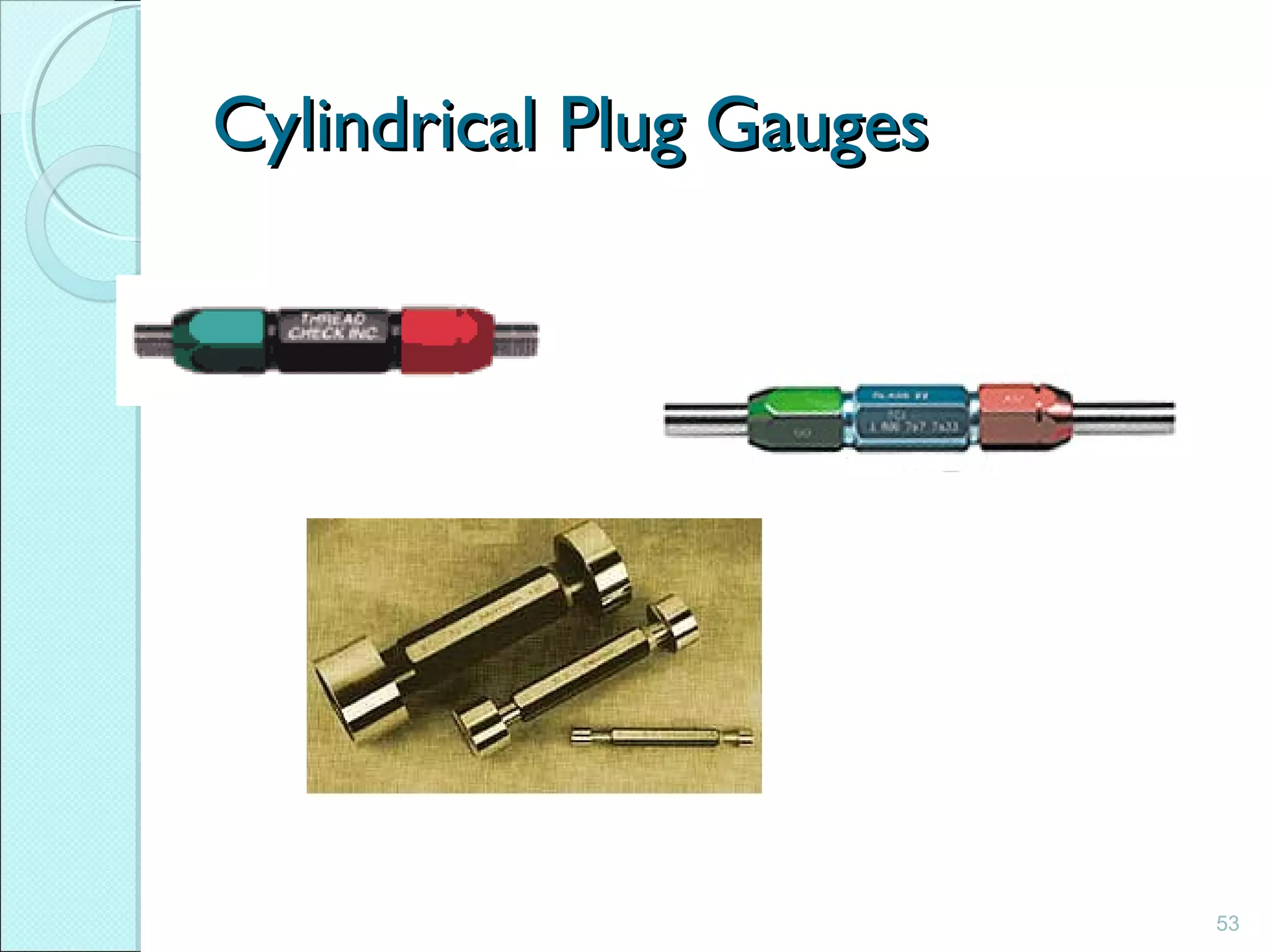
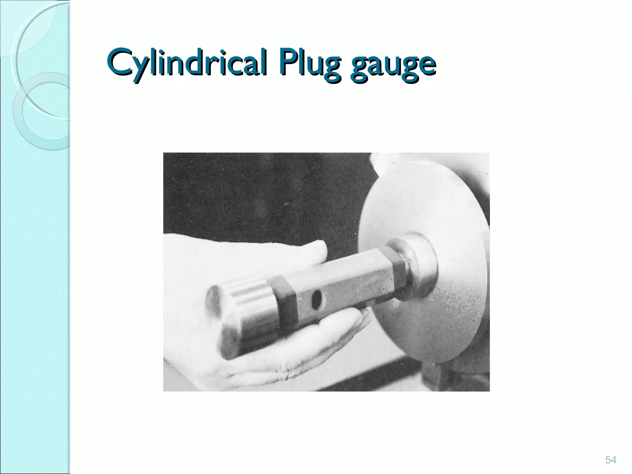
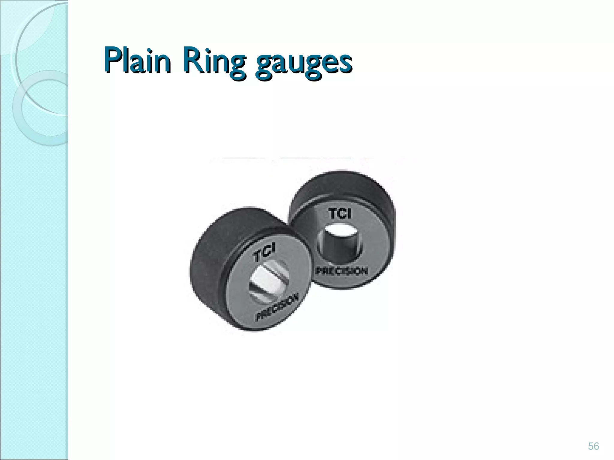
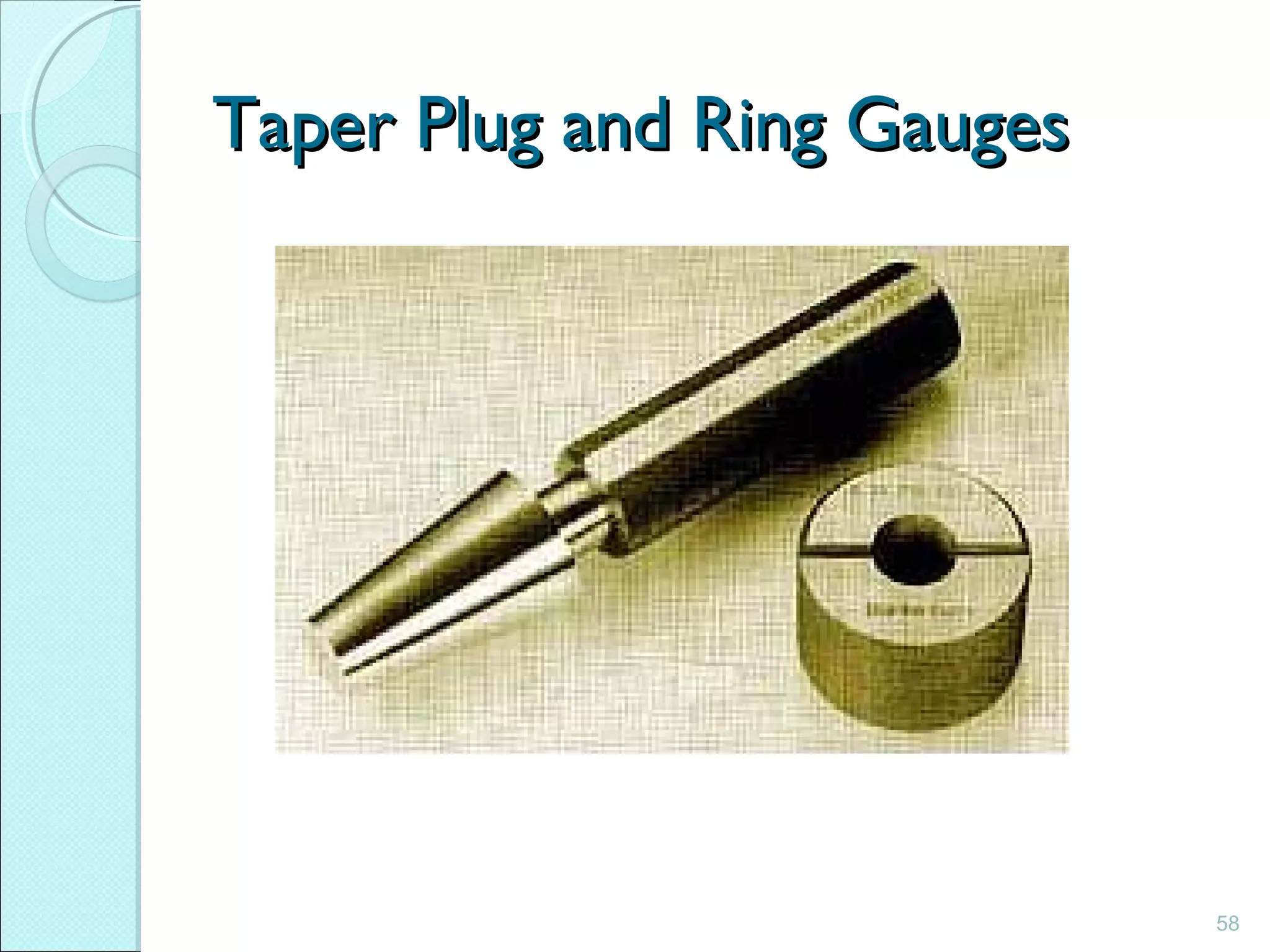
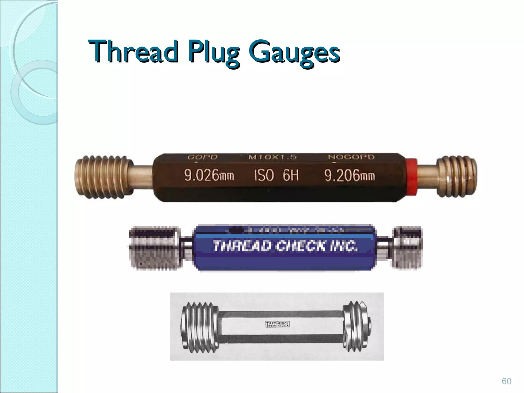
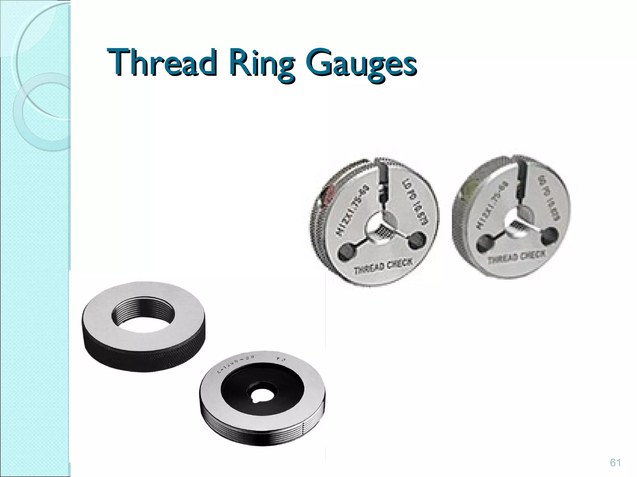
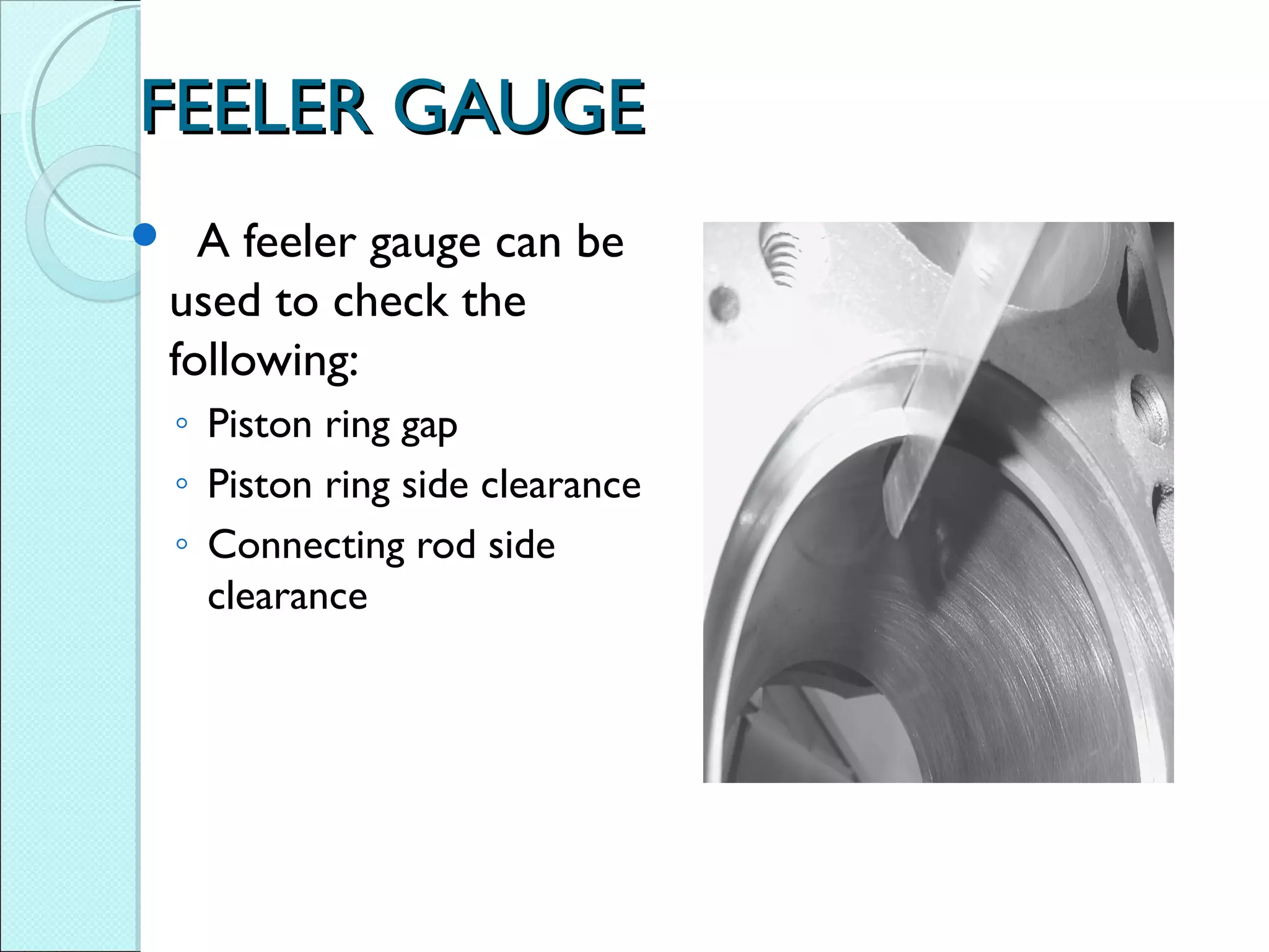
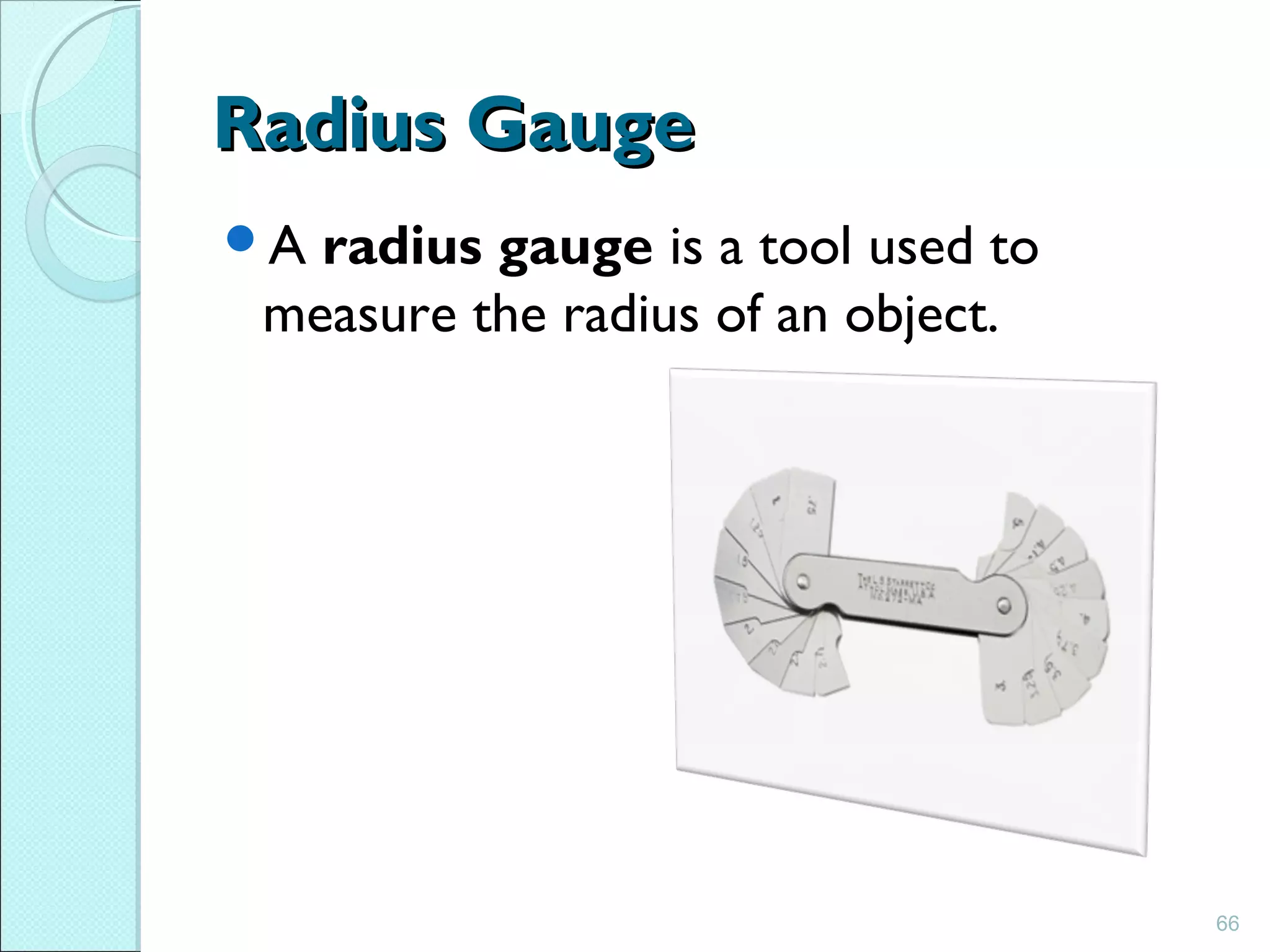

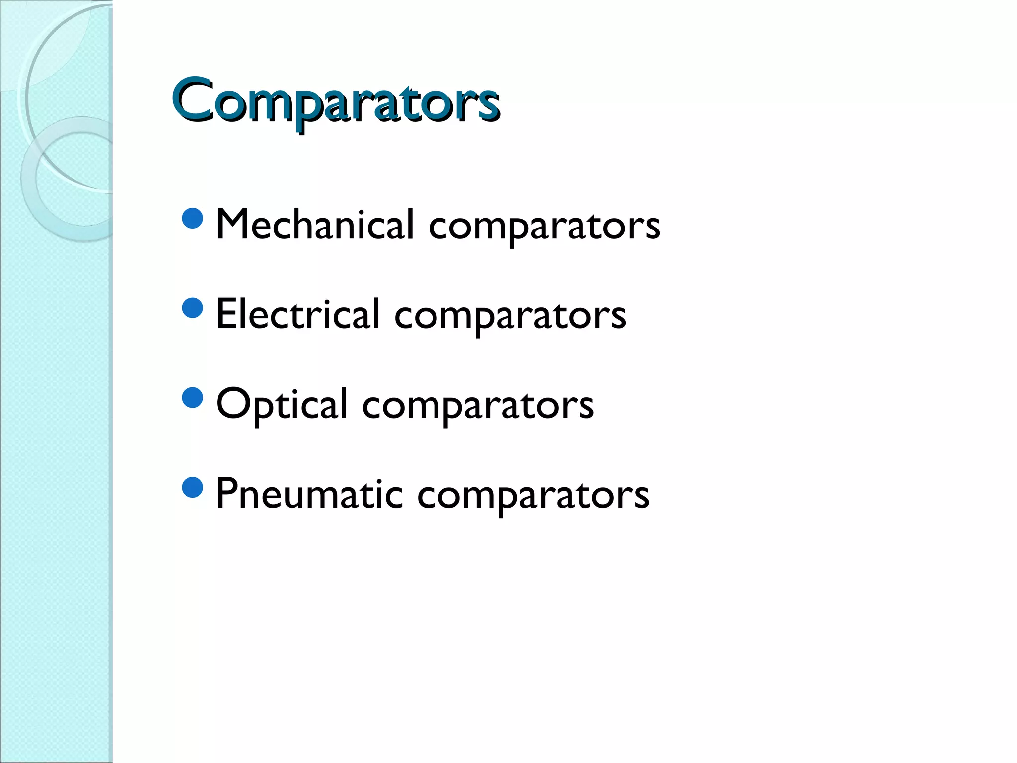
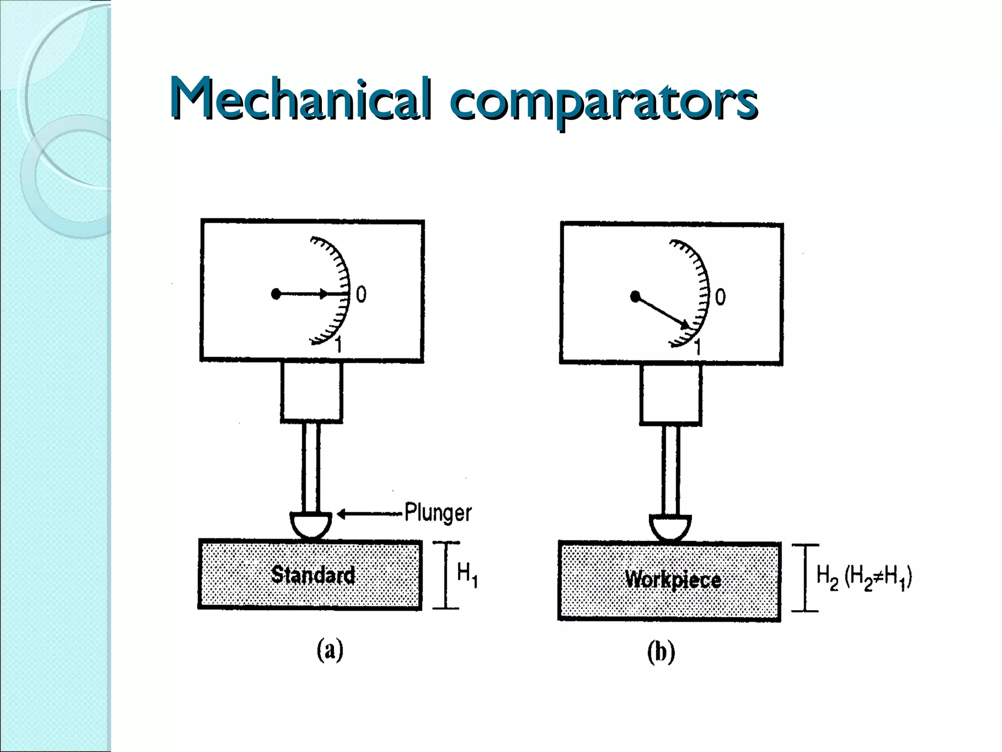


The document discusses various linear and angular measurement instruments. It describes vernier calipers, micrometers, slip gauges, interferometers, and comparators which are used for linear measurement. Angular measurements are made using instruments like sine bars and protractors. The document also discusses different types of gauges like plug, ring, and thread gauges used for dimensional inspection of parts.


