


The document outlines disaster recovery architecture using Amazon Web Services (AWS) with three blueprints, each highlighting different configurations for main and disaster recovery sites. It discusses key components and their functionalities like managed DNS, load balancing, and database replication, while weighing the pros and cons of each architecture. Recommendations for suitable use cases are provided for each blueprint, addressing scalability, availability, and cost-effectiveness.
Introduction to disaster recovery architecture using AWS, mentioning key elements like DNS, load balancers, and high availability.
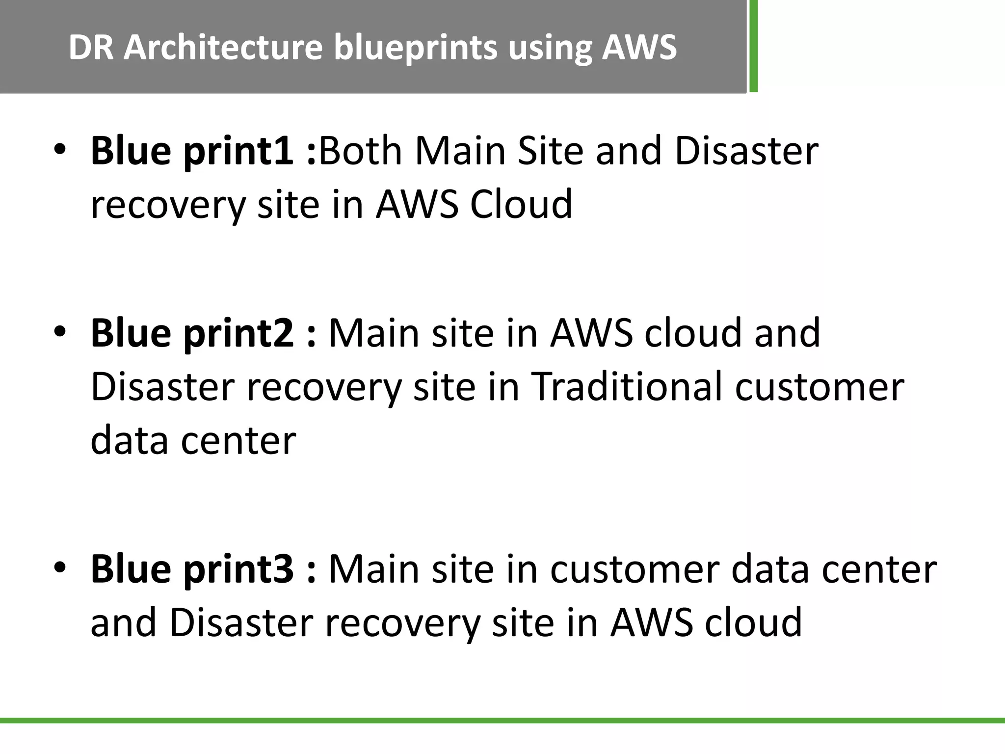
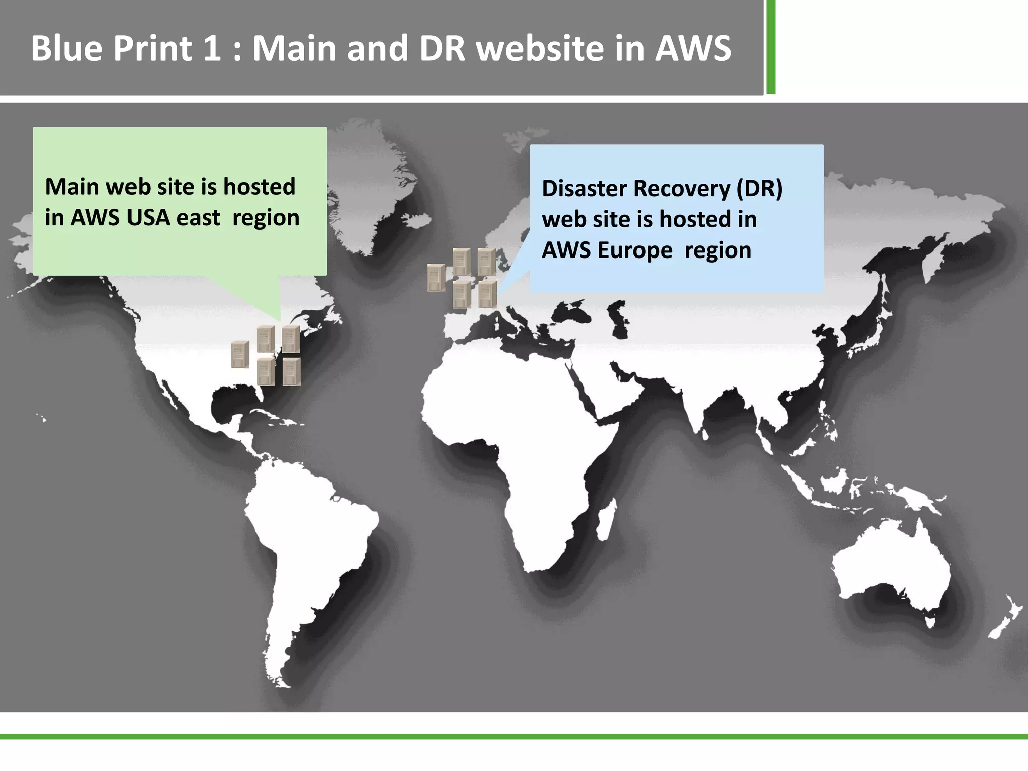
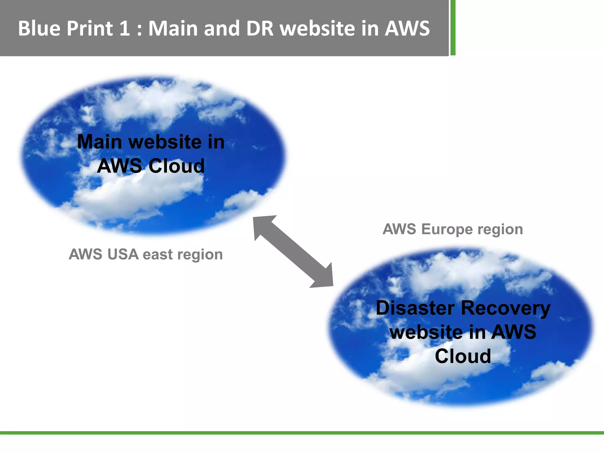
Explains three blueprints for disaster recovery: both sites in AWS, main site in AWS and DR in traditional center, and vice versa.
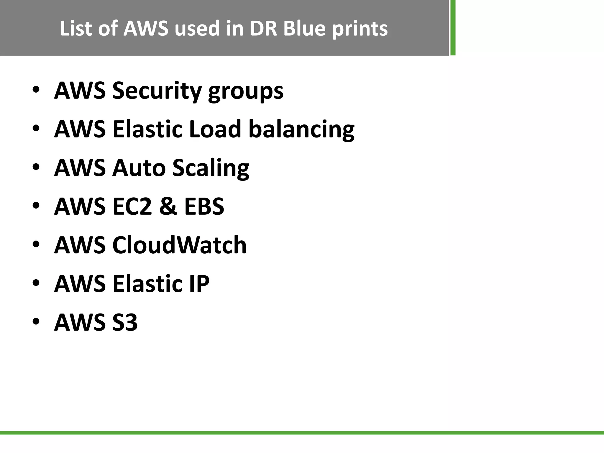
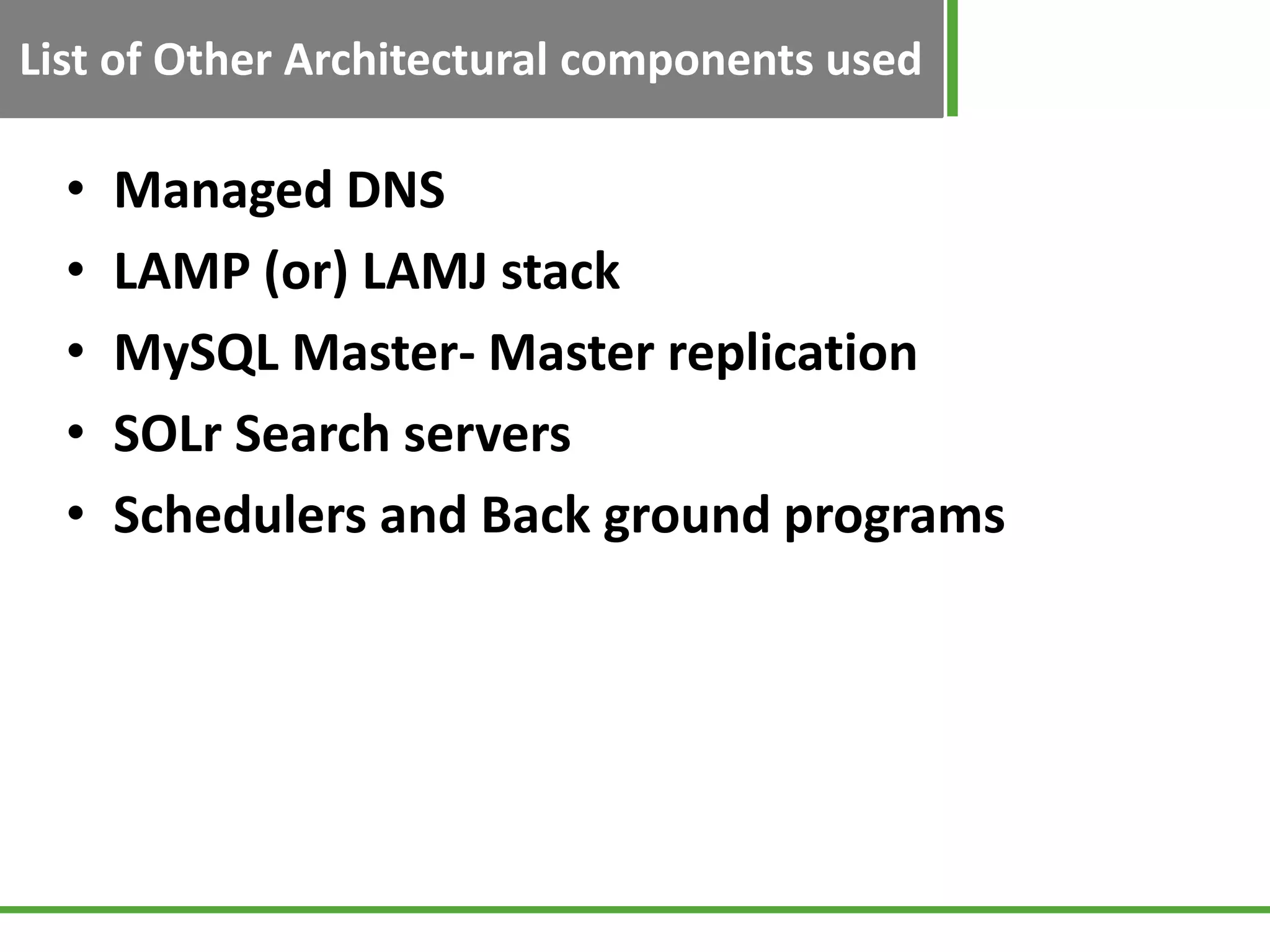
Lists AWS tools used in DR blueprints such as Security Groups, Elastic Load Balancing, EC2, EBS, and other components like DNS and MySQL replication.
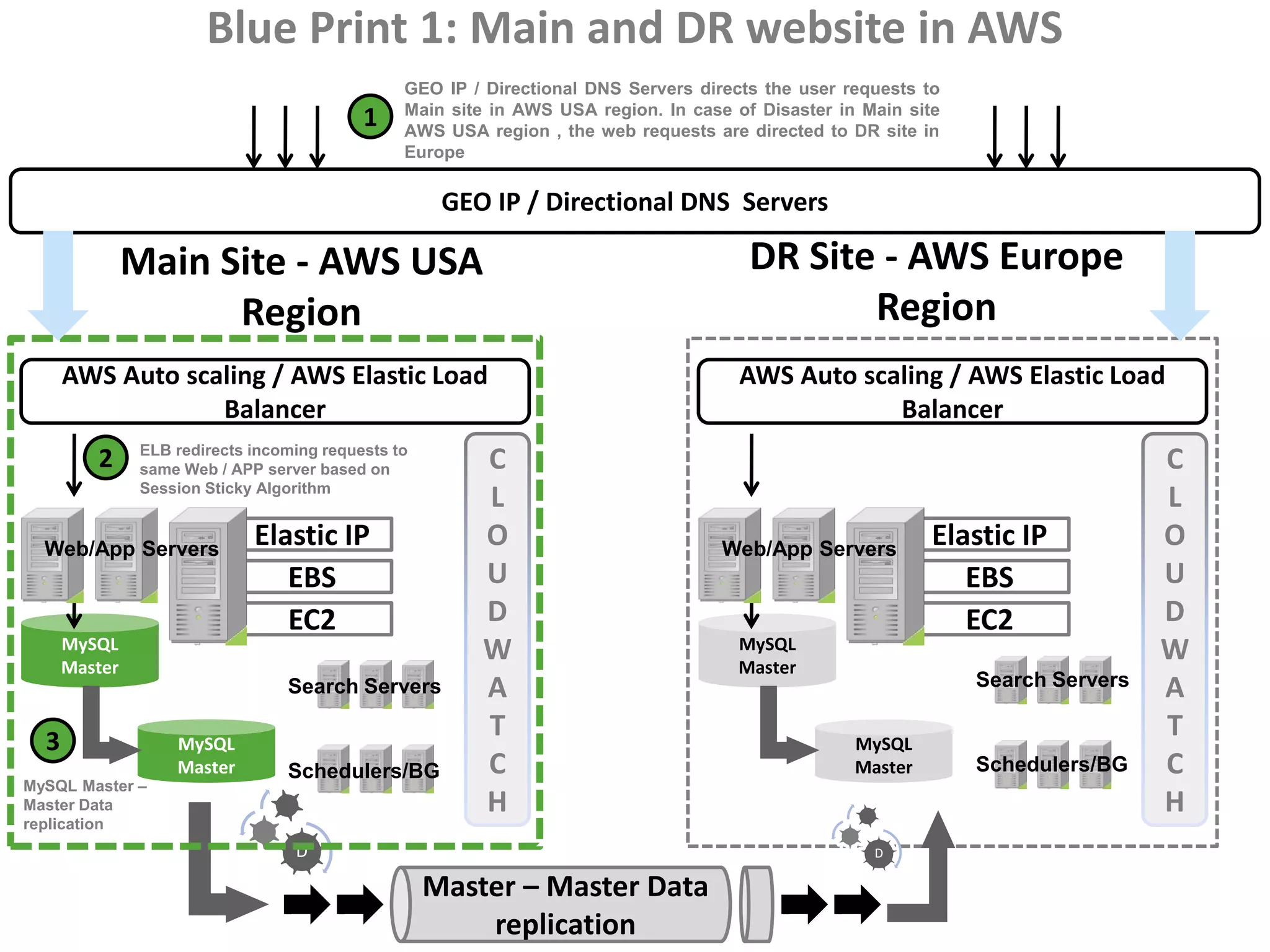
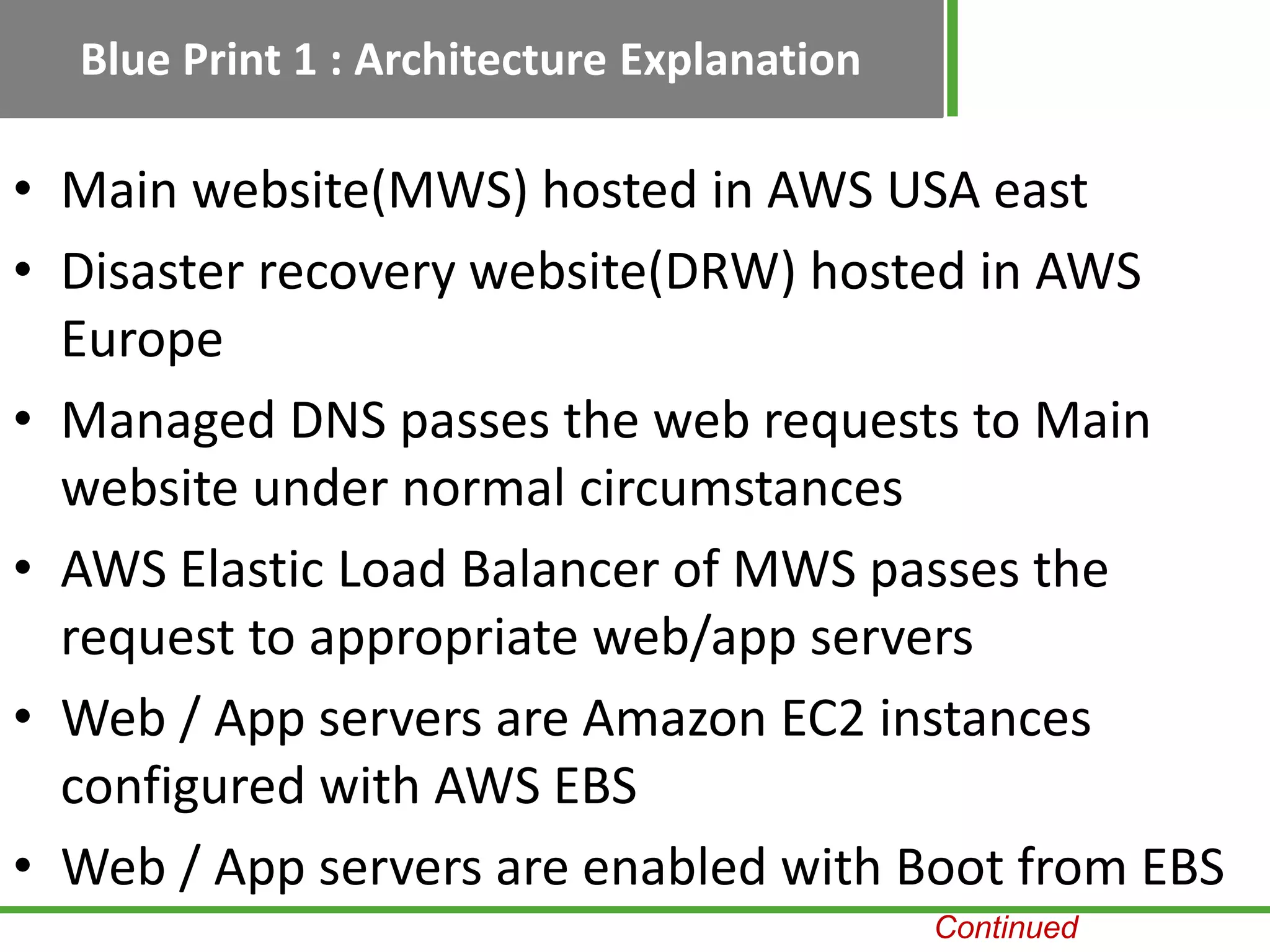
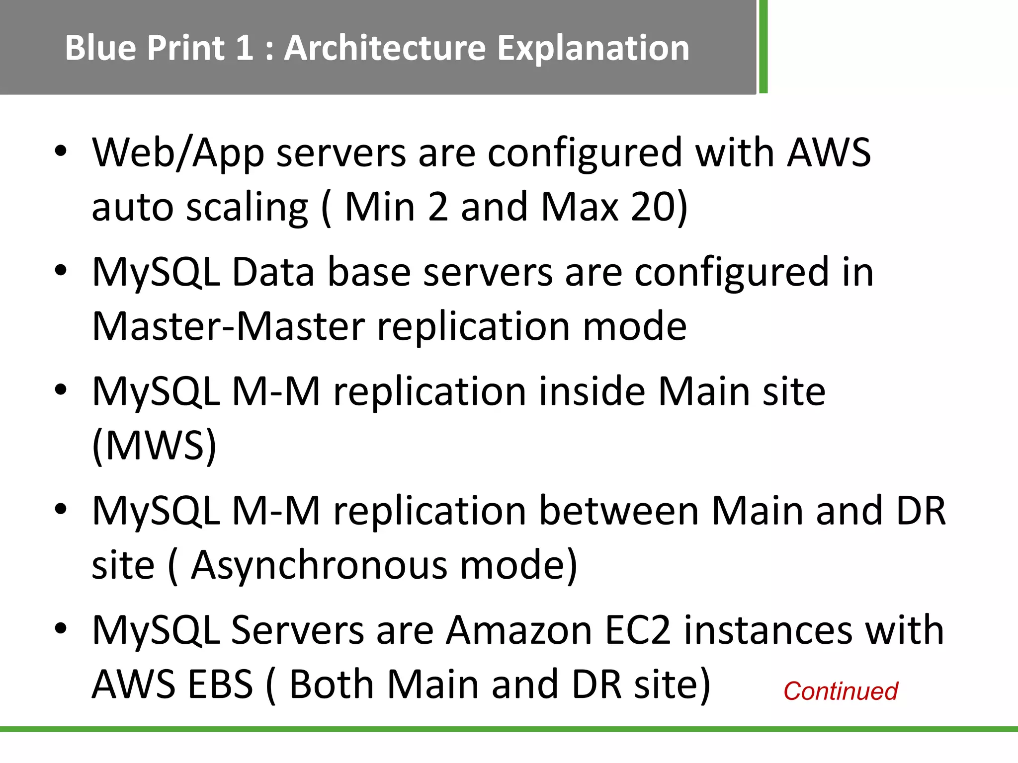
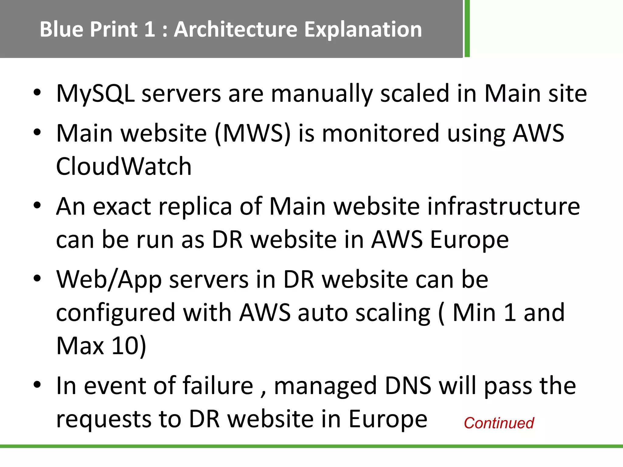
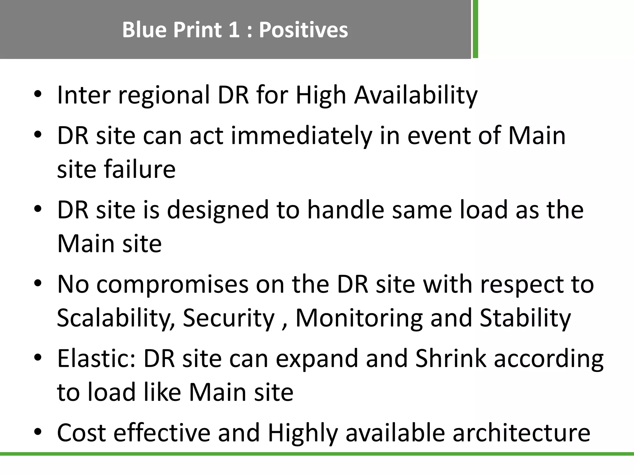
Details Blueprint 1 where both main and DR sites are in AWS, discussing architecture elements like web servers, DNS, load balancers, scaling, and replication.
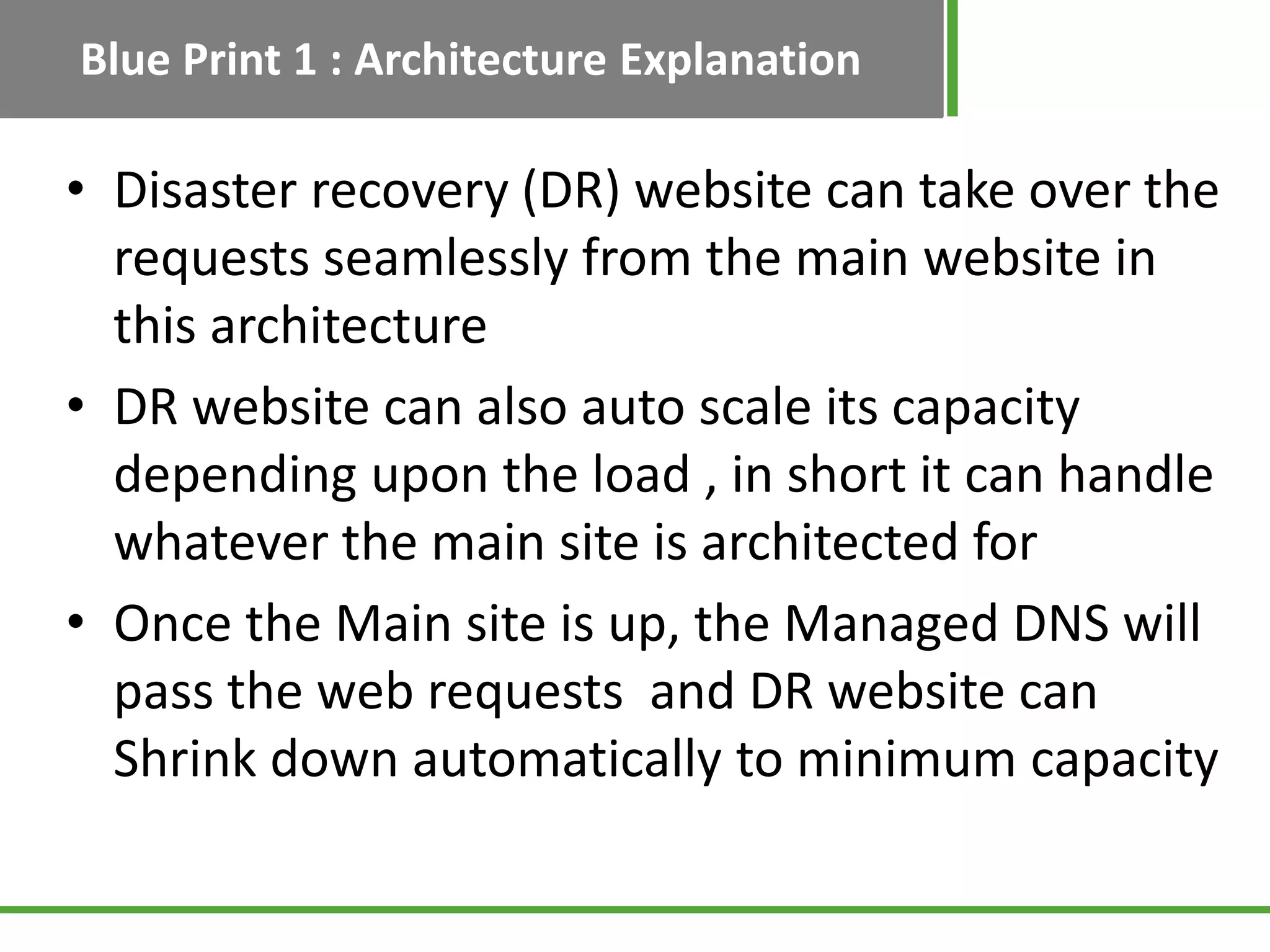
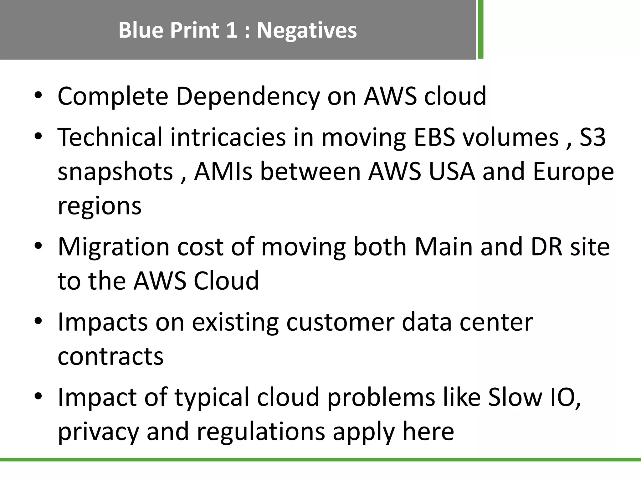
Highlights benefits of Blueprint 1 such as high availability and elasticity, alongside concerns regarding dependency on AWS and migration costs.
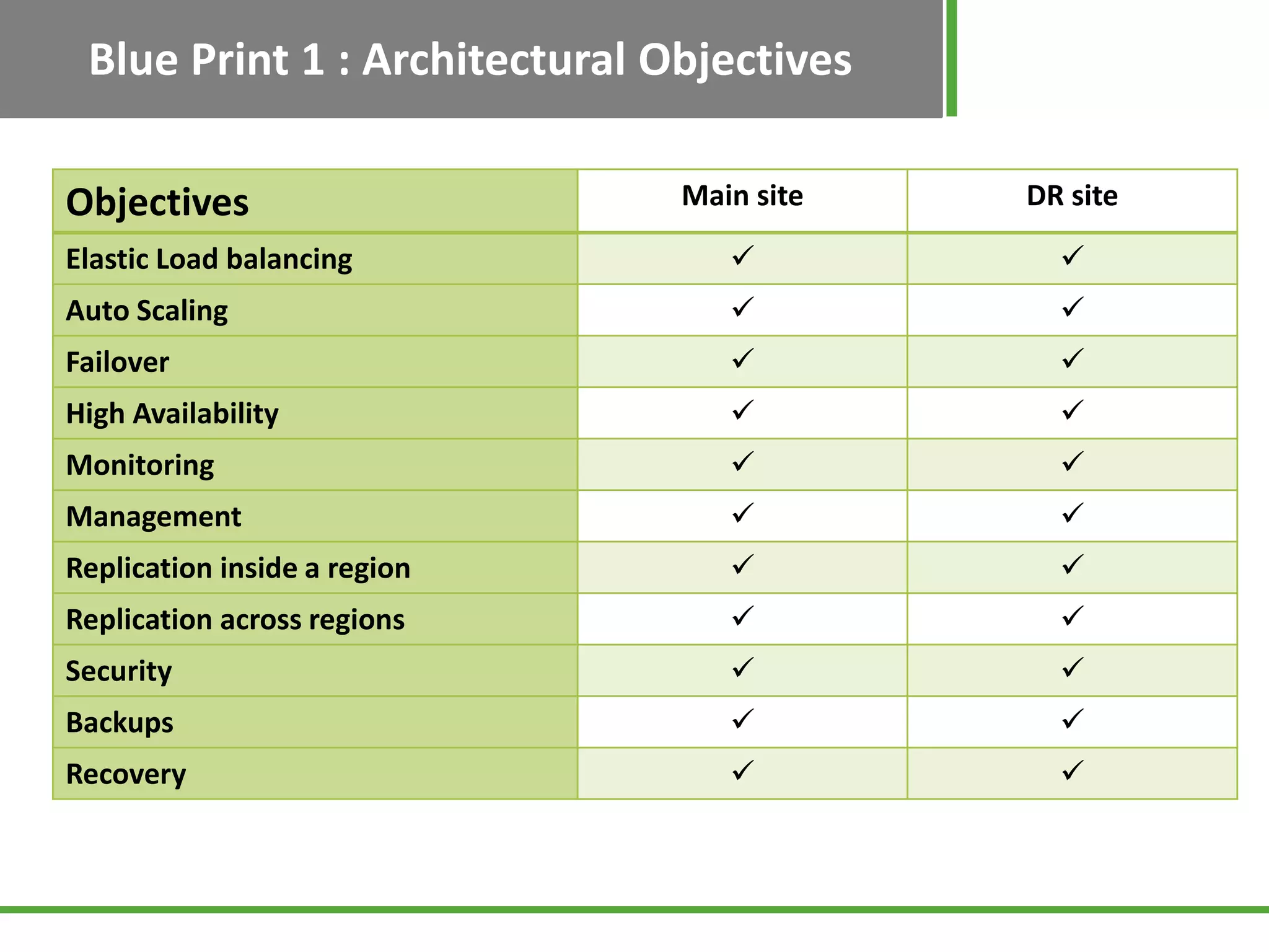
Shows architectural objectives for both main and DR sites, emphasizing key functionalities like load balancing and monitoring.
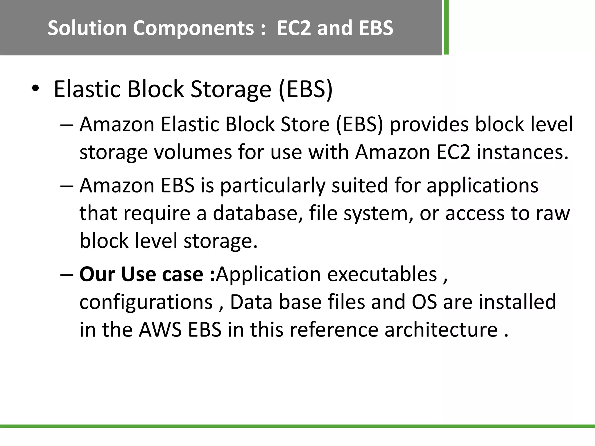
Discusses EBS and S3 as critical components for storage and data management in disaster recovery solutions.
Explains the significance of AWS Elastic Load Balancer and Auto Scaling in managing application traffic and adapting to load changes.
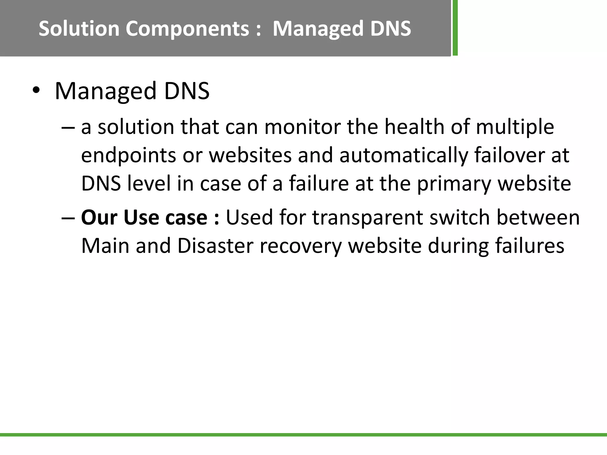
Describes AWS CloudWatch monitoring capabilities and the role of Managed DNS in ensuring seamless recovery.
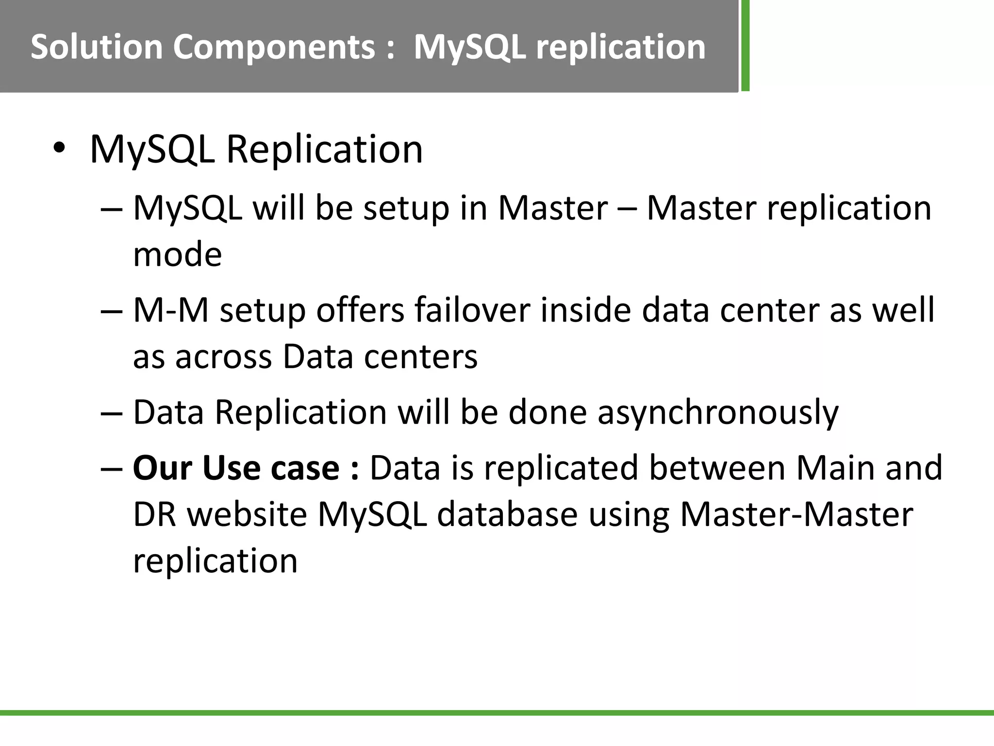
Explains the setup and benefits of MySQL Master-Master replication for data integrity in DR architecture.
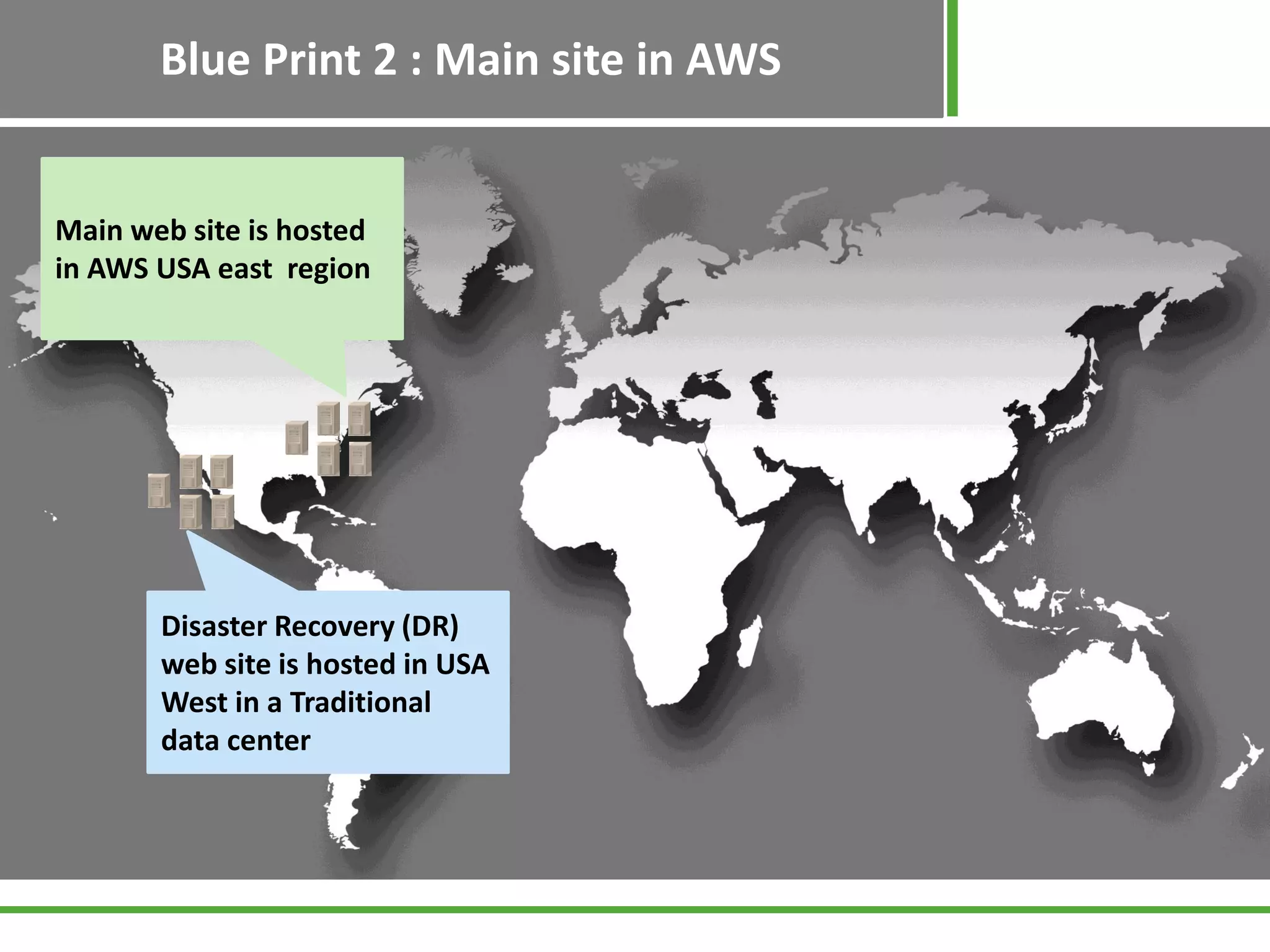
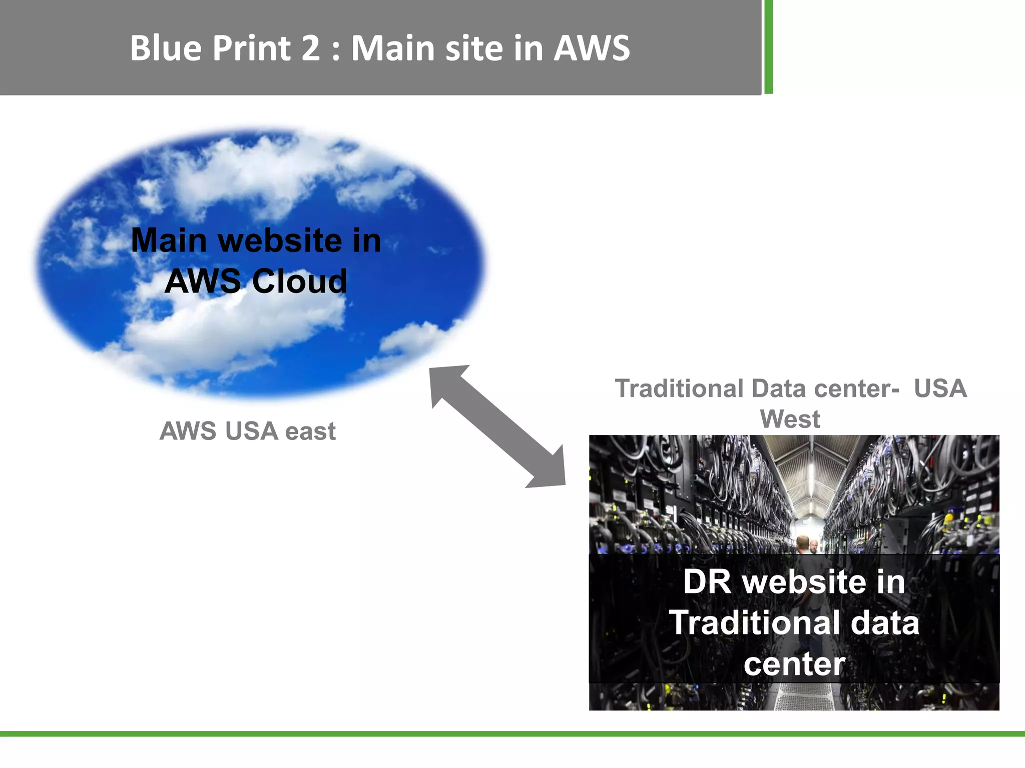
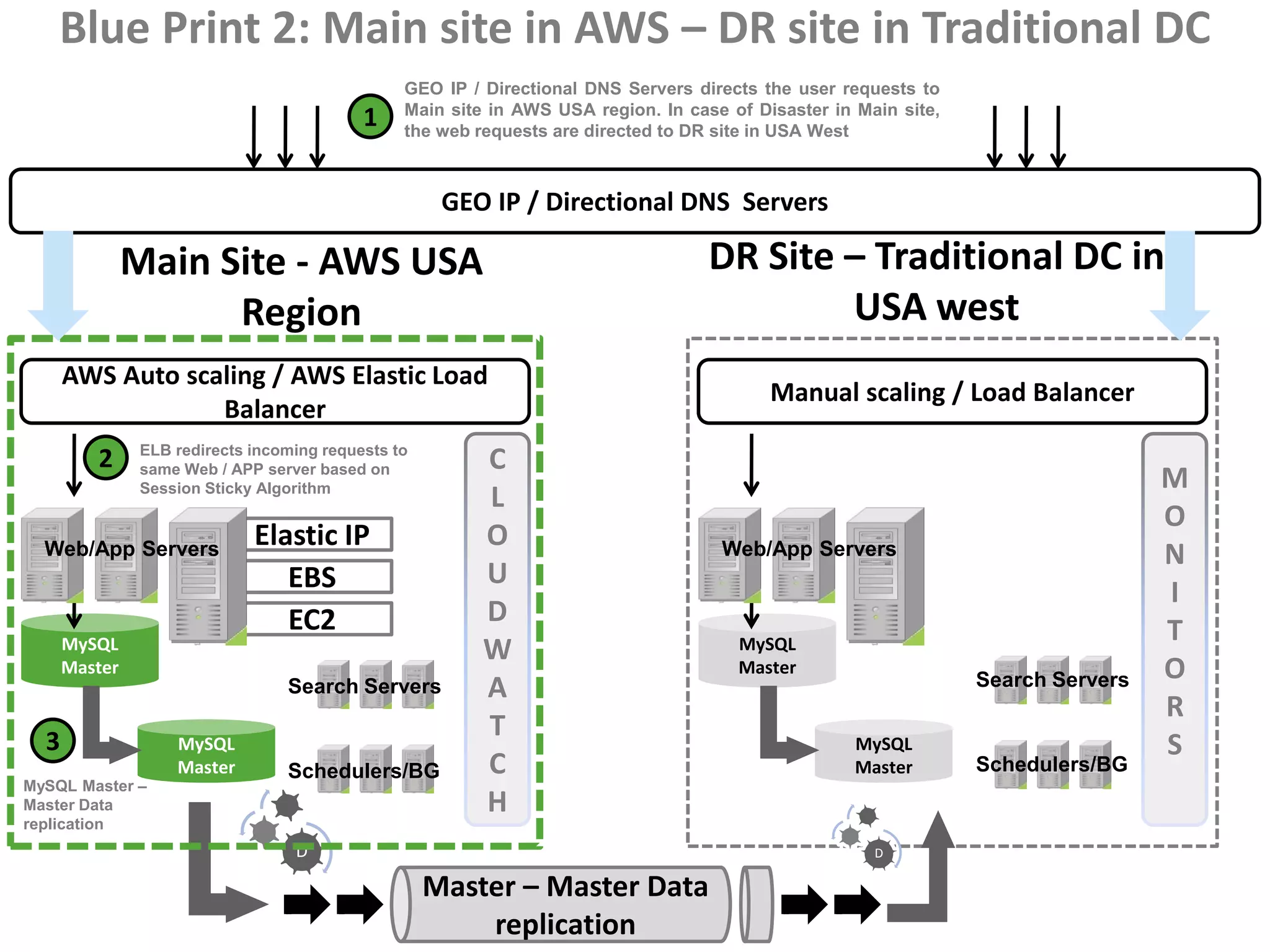
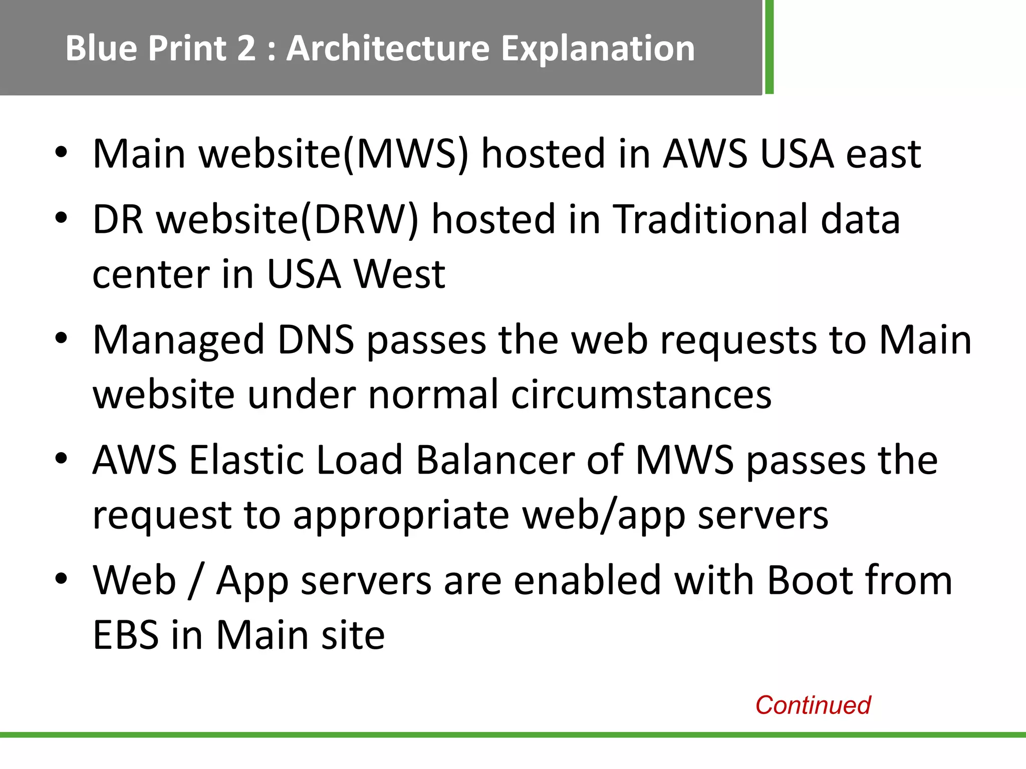
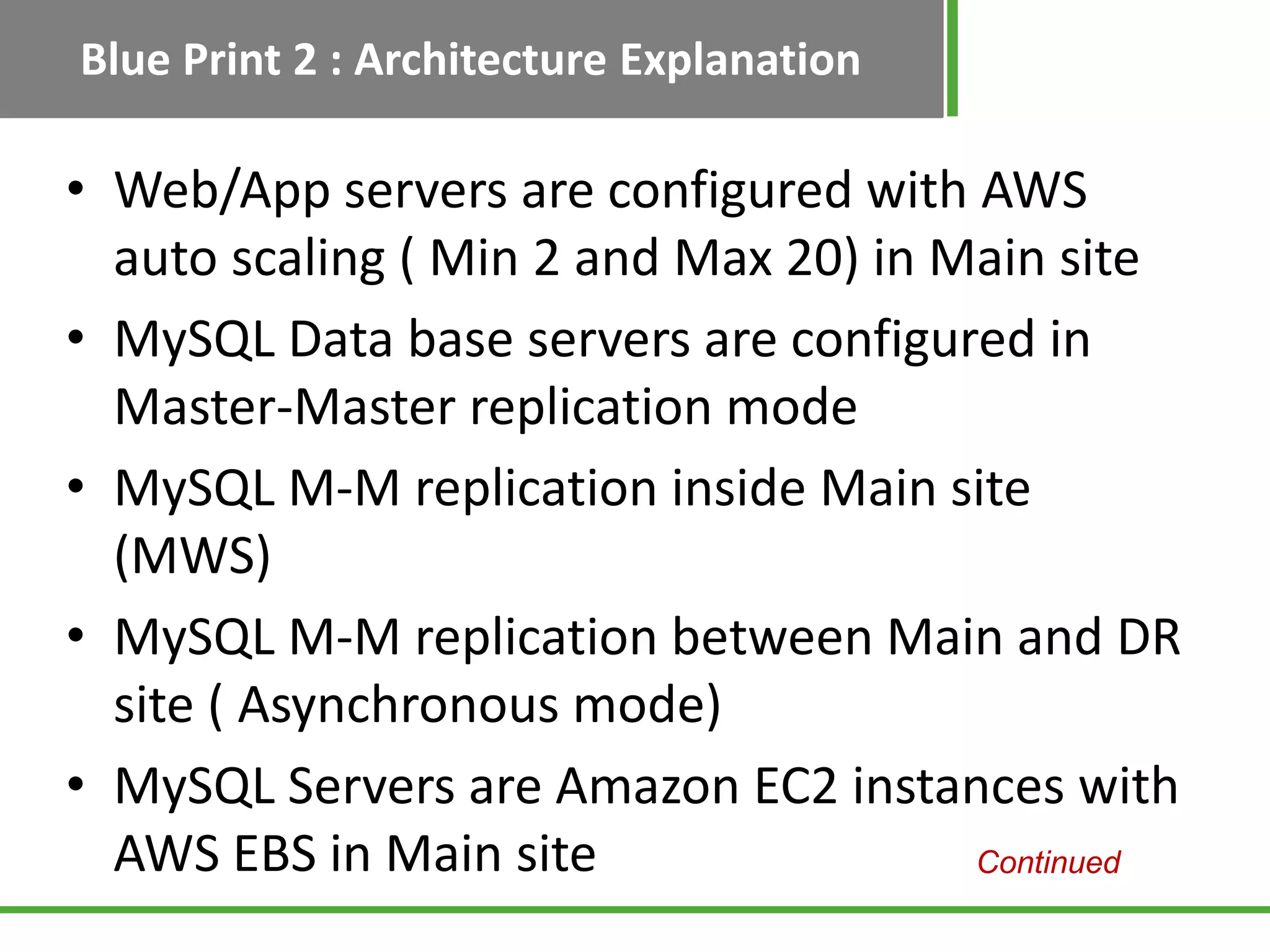
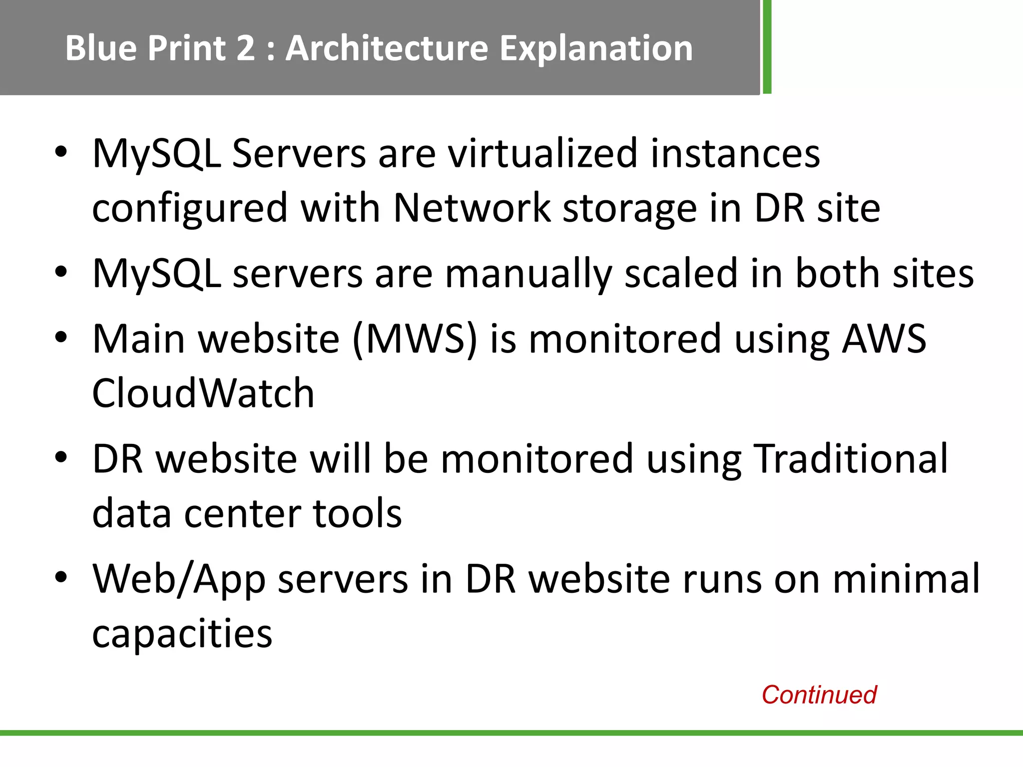
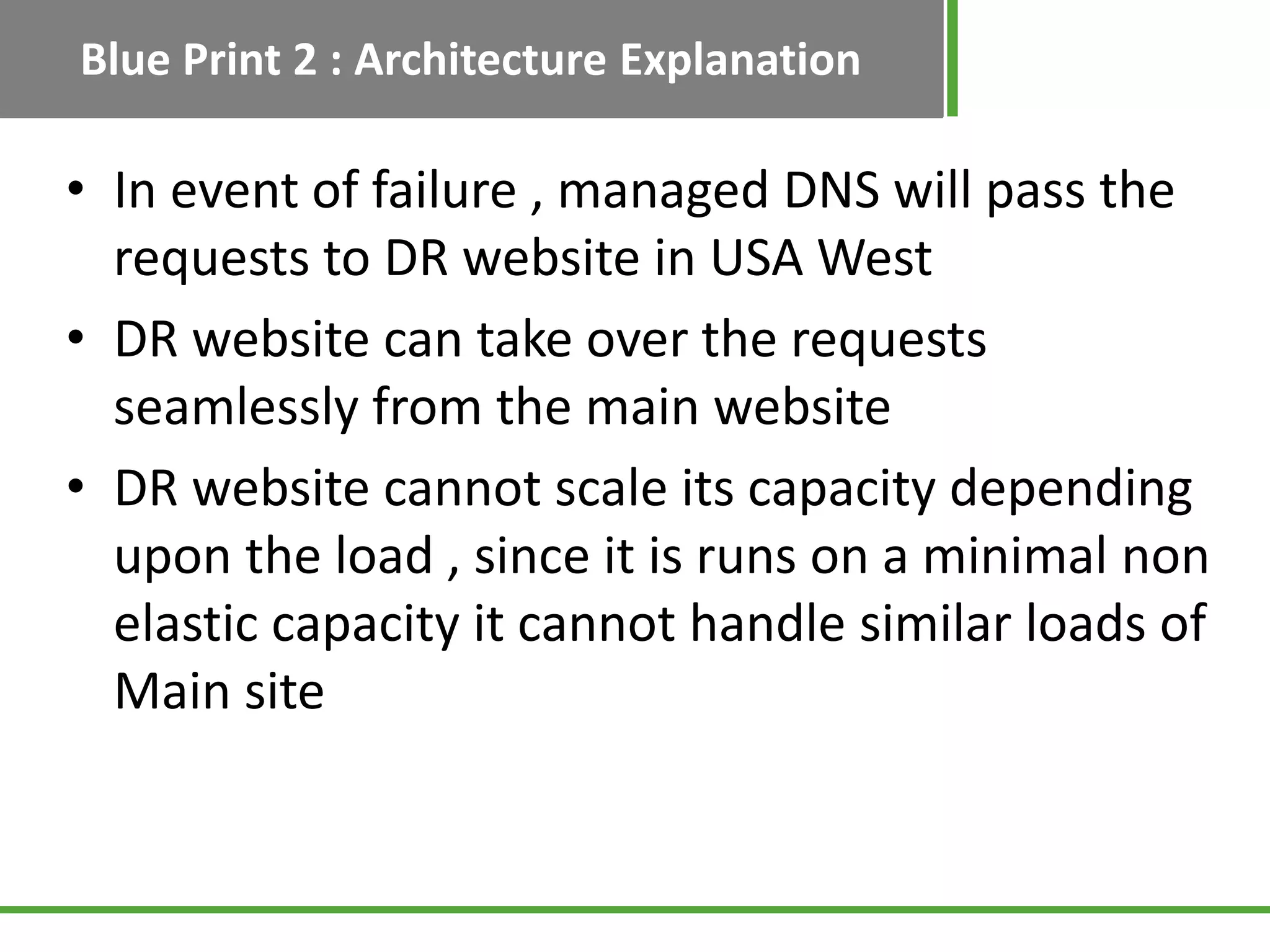
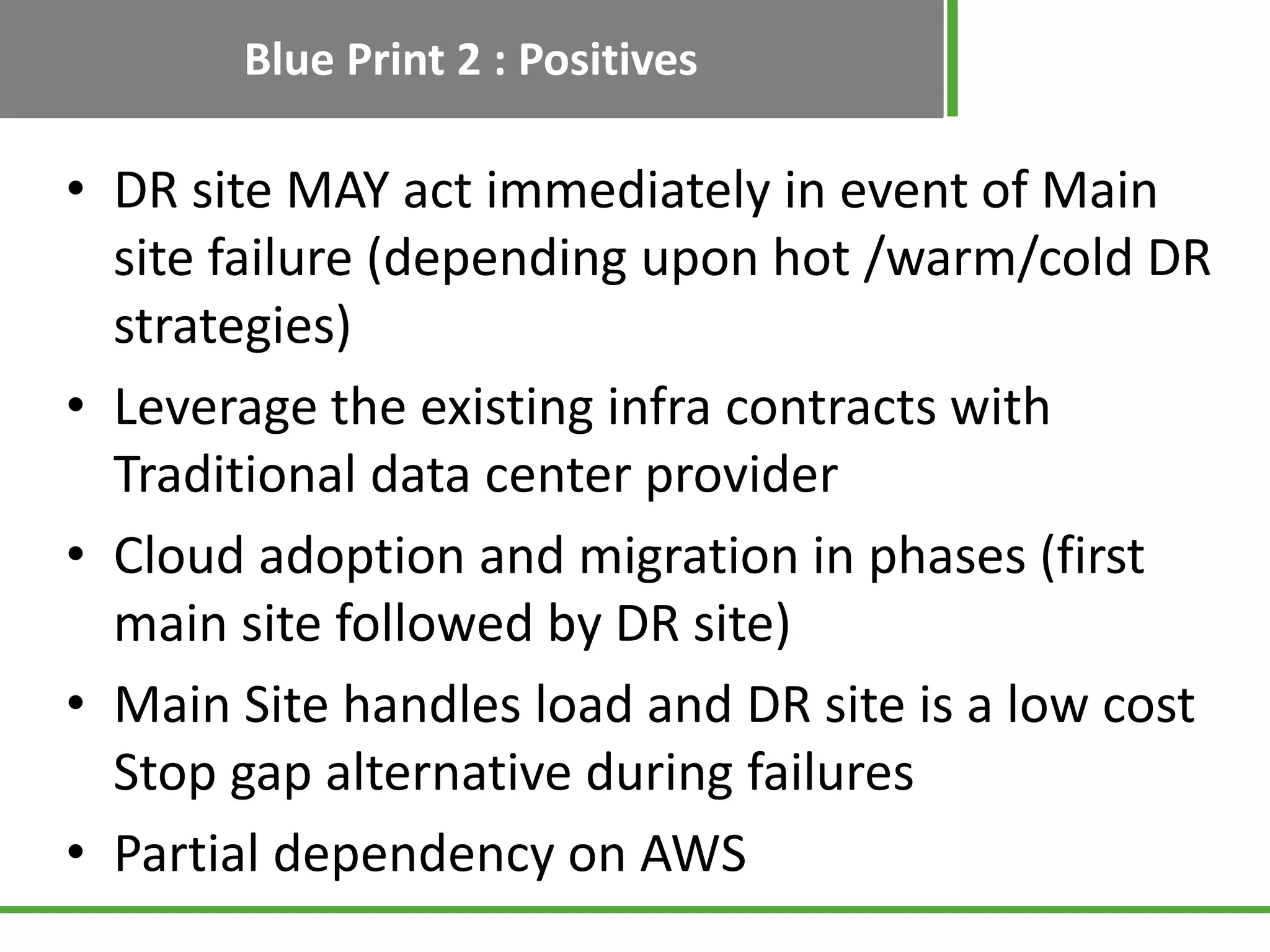
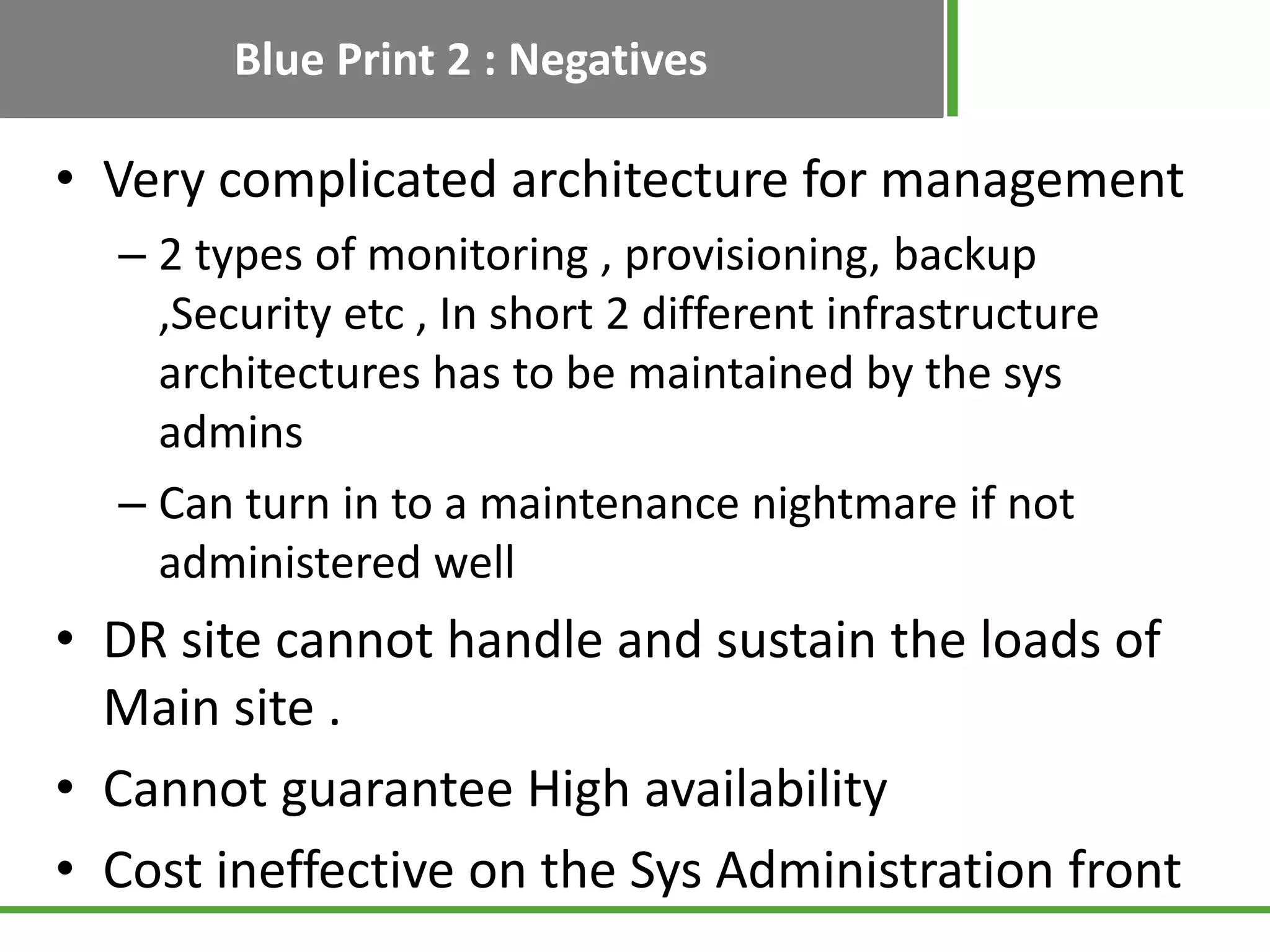
Details on Blueprint 2 where the main site is in AWS and DR is in a traditional center, including its architecture and scalability challenges.
Lists objectives for Blueprint 2 functionality and highlights the complexities and potential issues related to maintaining a hybrid architecture.
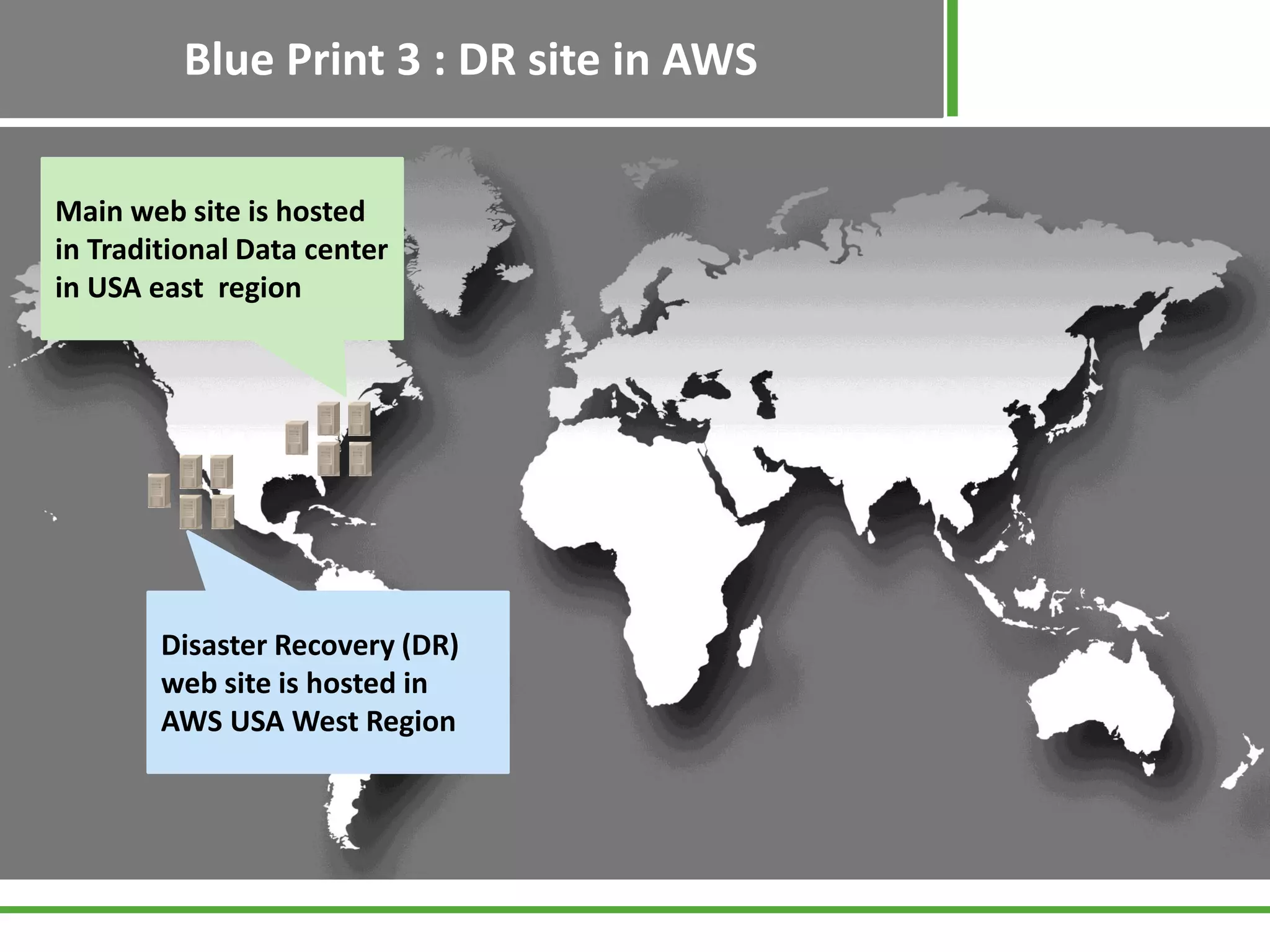
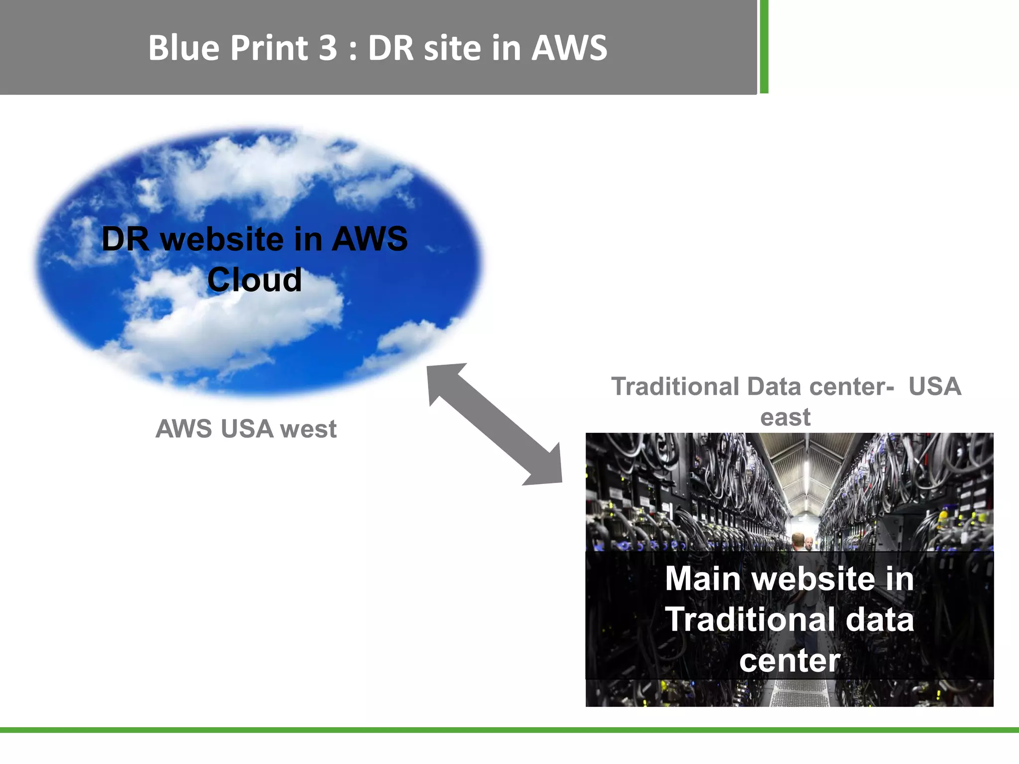
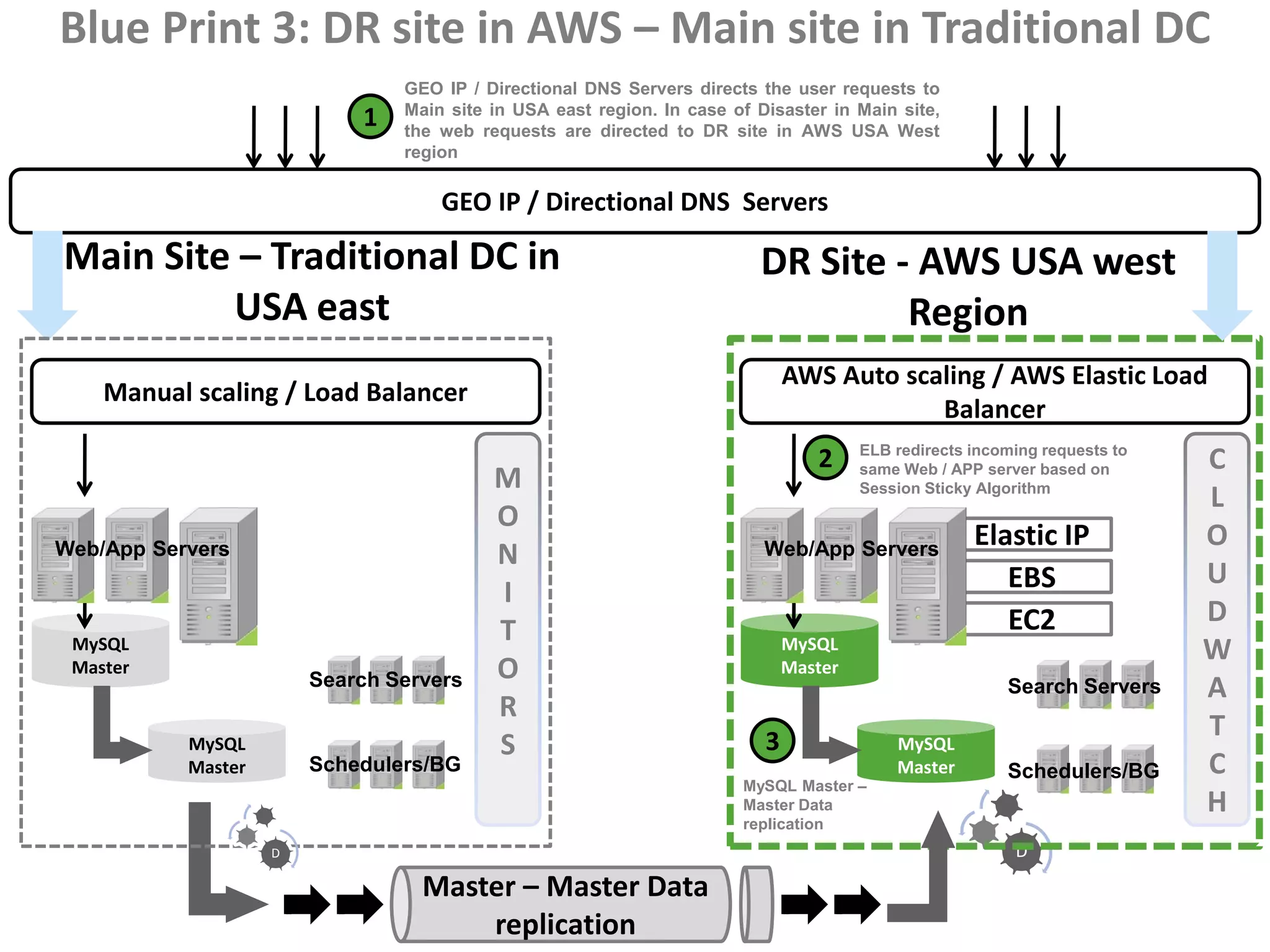
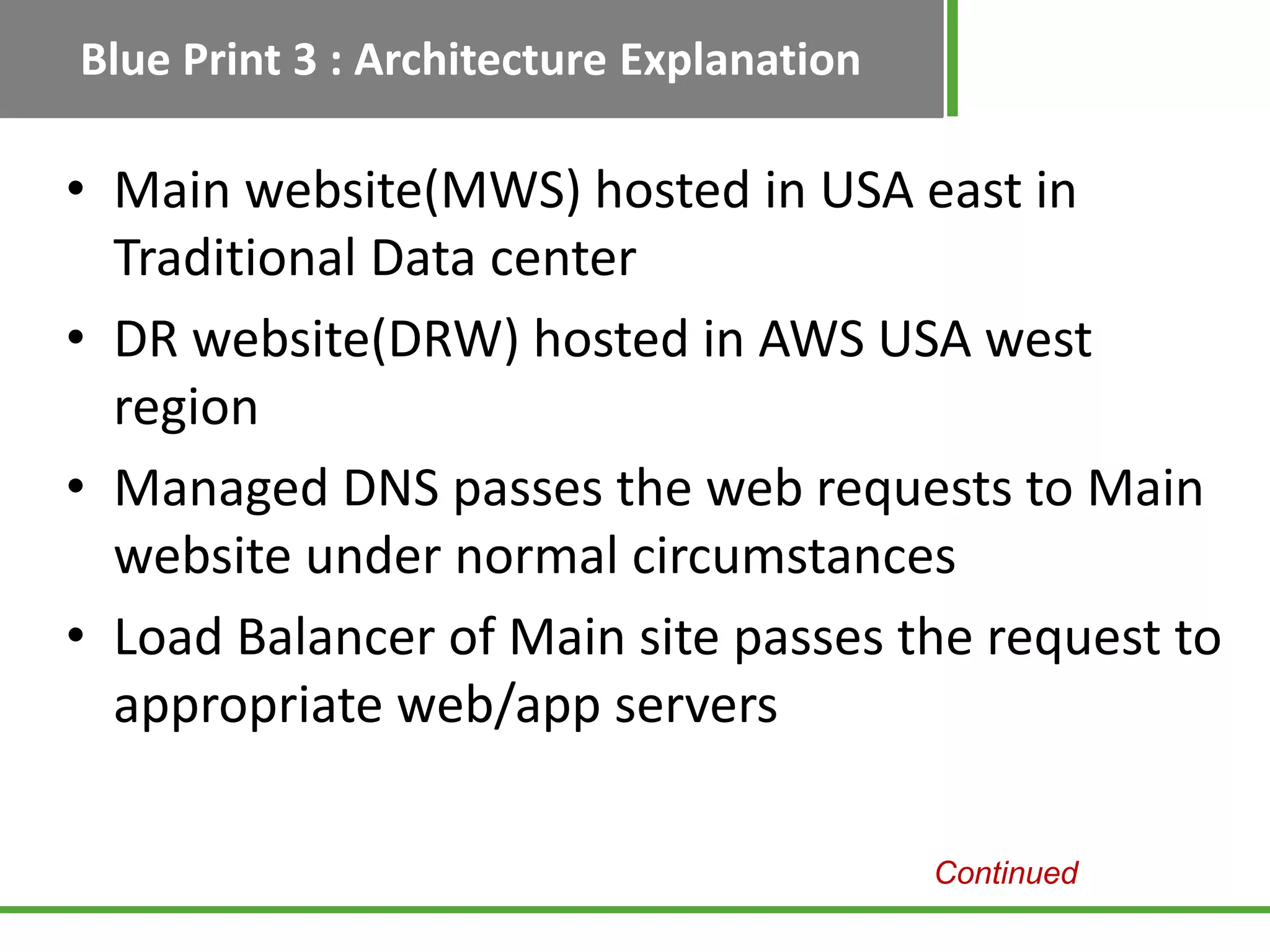
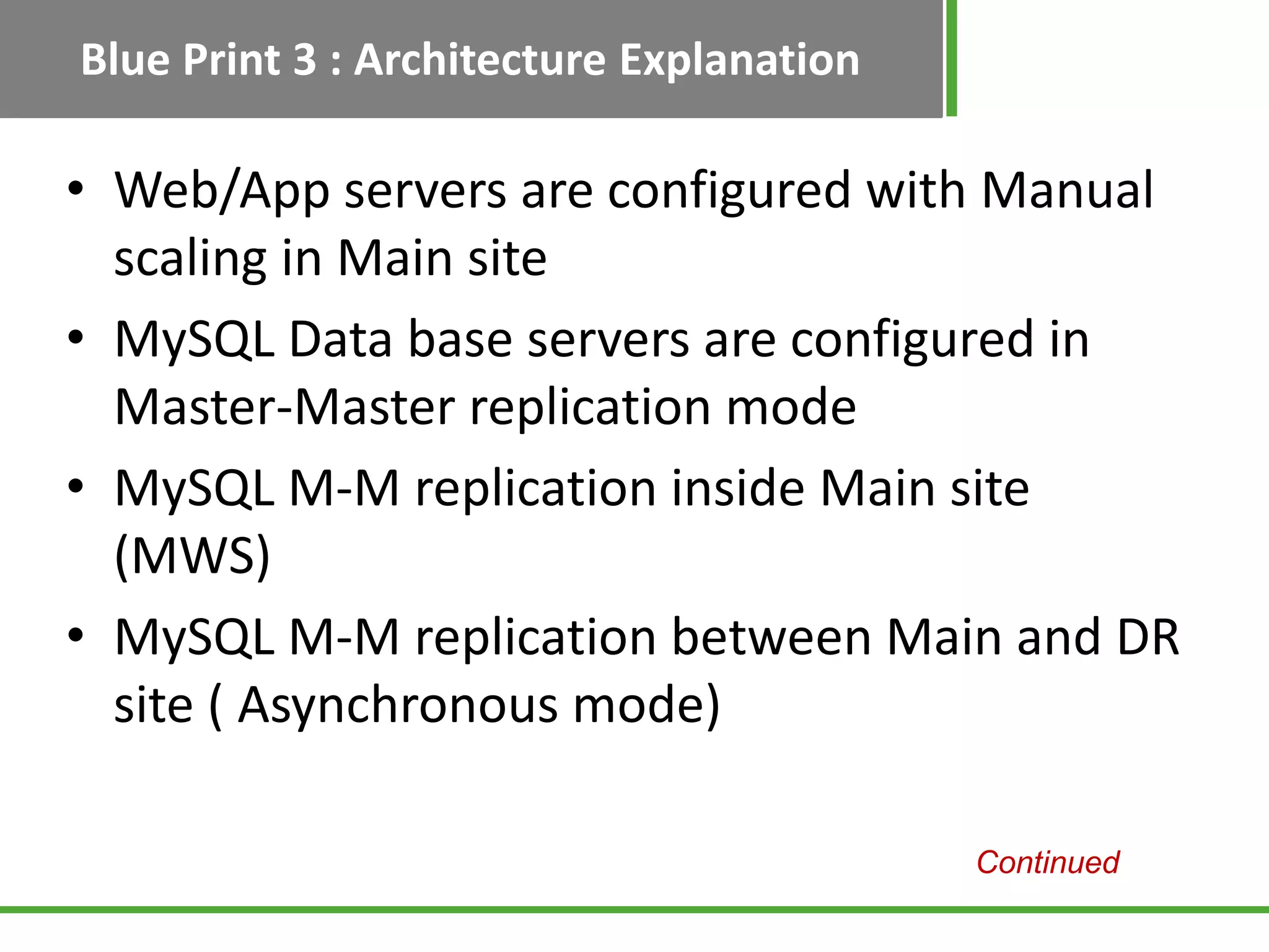
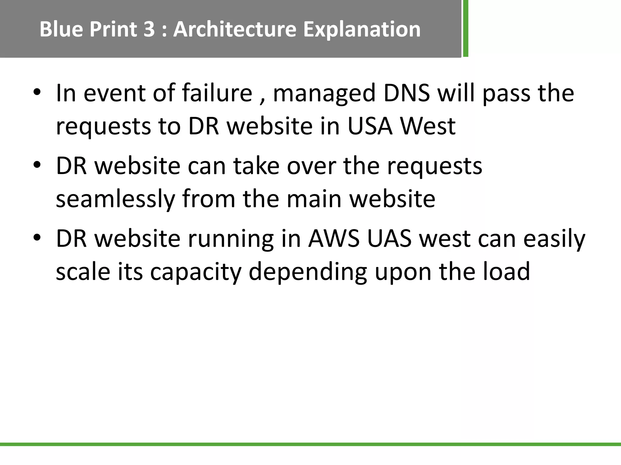
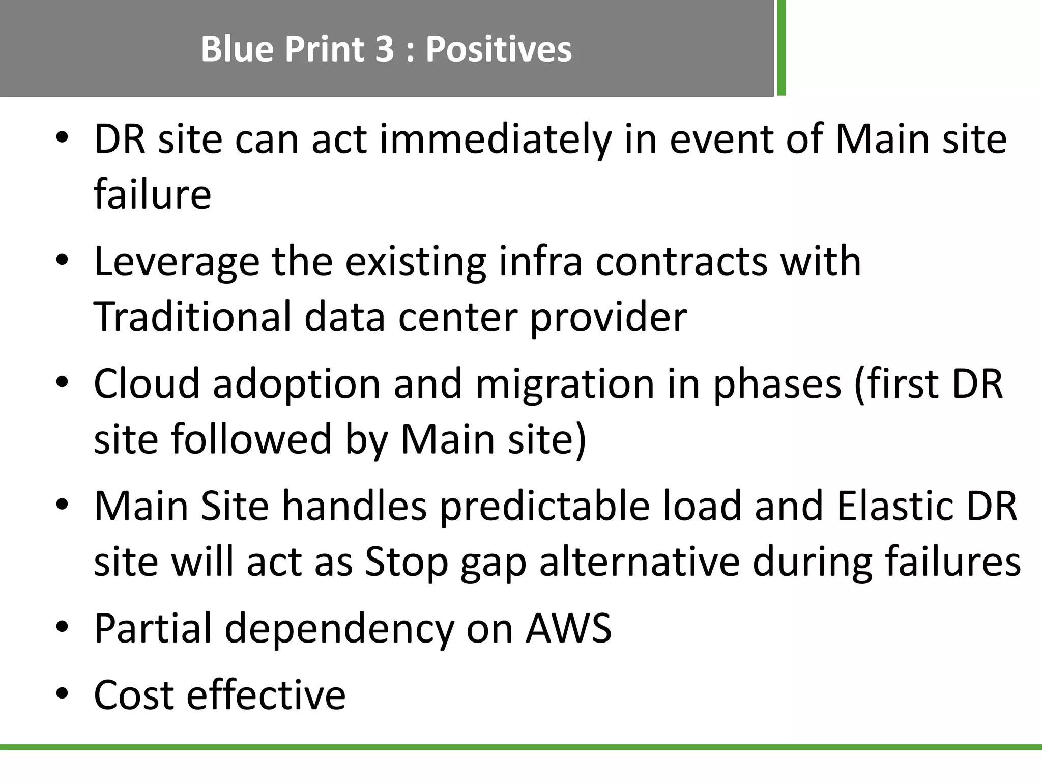
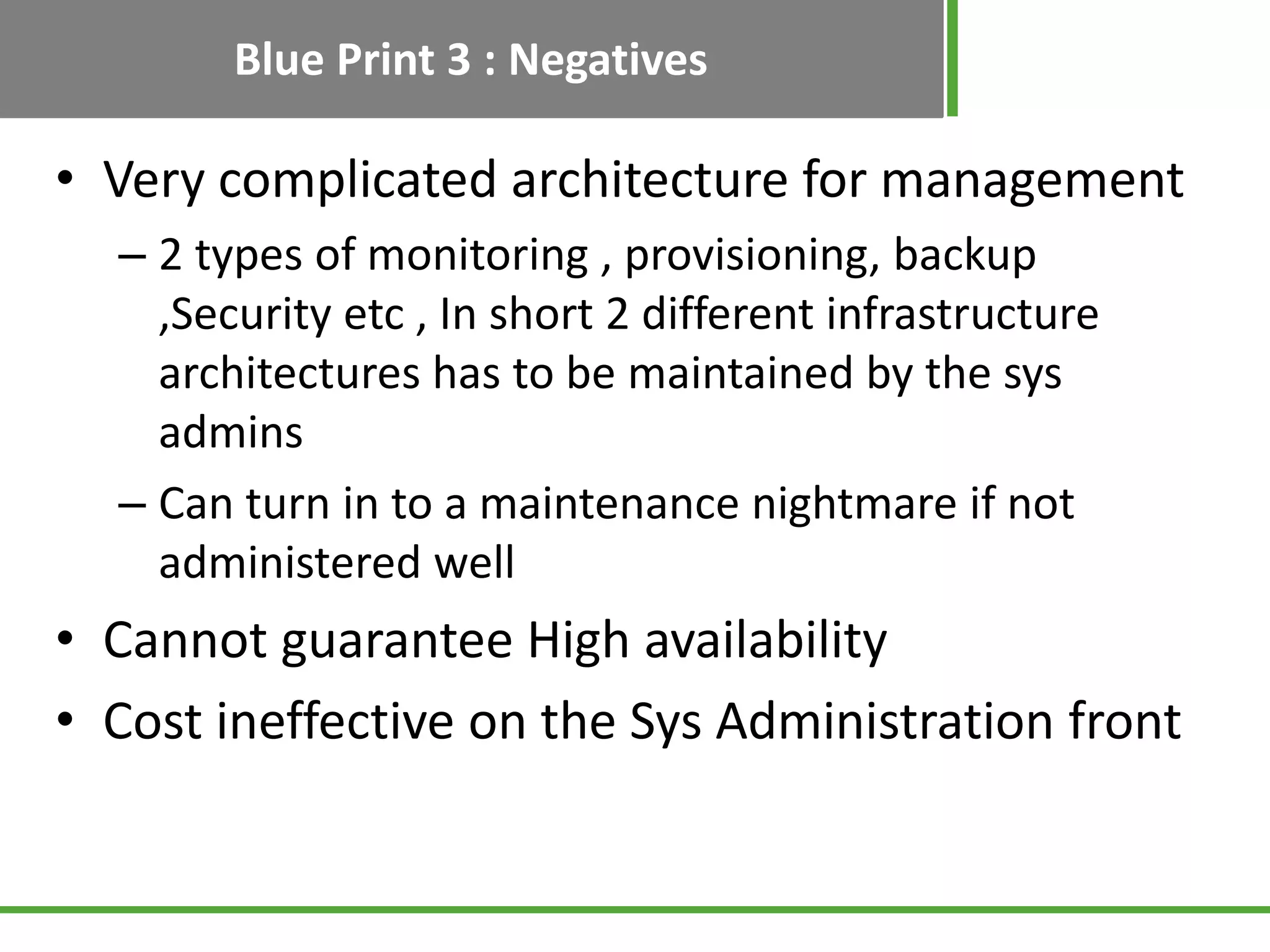
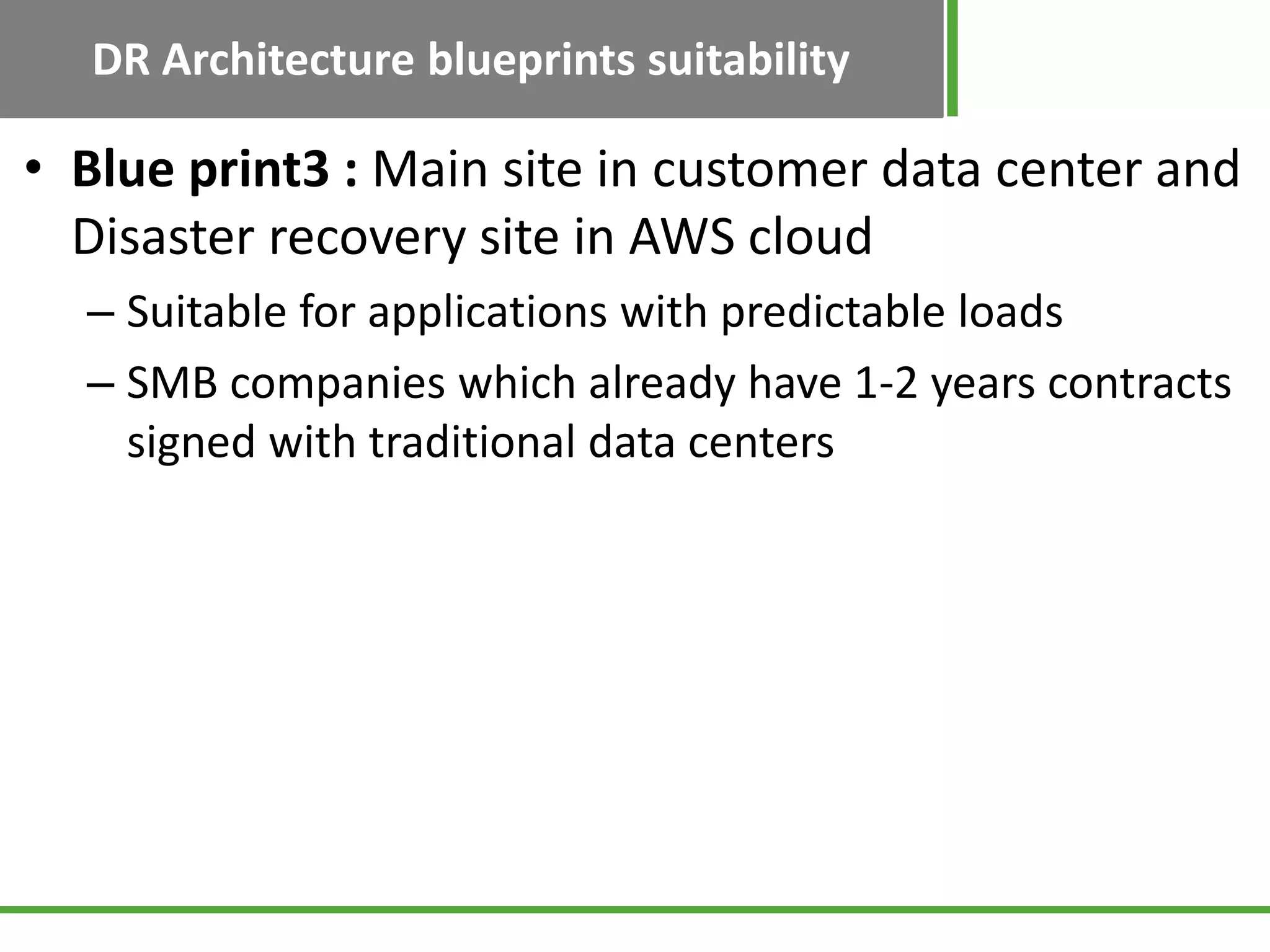
Explains Blueprint 3 with the main site in a traditional center and DR in AWS, focusing on scaling, challenges, and architectural objectives.
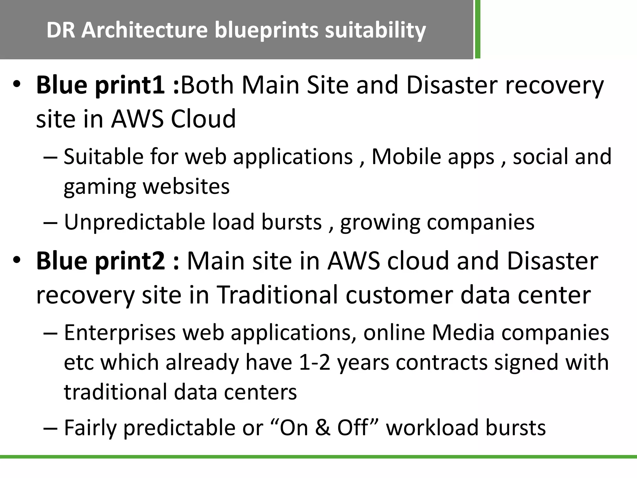
Discusses the suitability of the three blueprints based on operational needs and existing infrastructure contracts.
Encourages working with experts to determine suitable cloud-based disaster recovery strategies.
Provides contact details for further inquiries related to AWS disaster recovery solutions.