Download to read offline
![Saturated Unit Weight
It is the ratio of saturated weight of soil to volume of soil
Symbol γsat
Submerged Unit Weight
It is the ratio of submerged weight of soil to volume of soil
Symbol γ'
γ'
=γsat −γw=γsat −9.81…….unit weight of water γw=9.81g/cc
Relation between density and unit weight
γ=ρ×g=ρ×9.81
---------
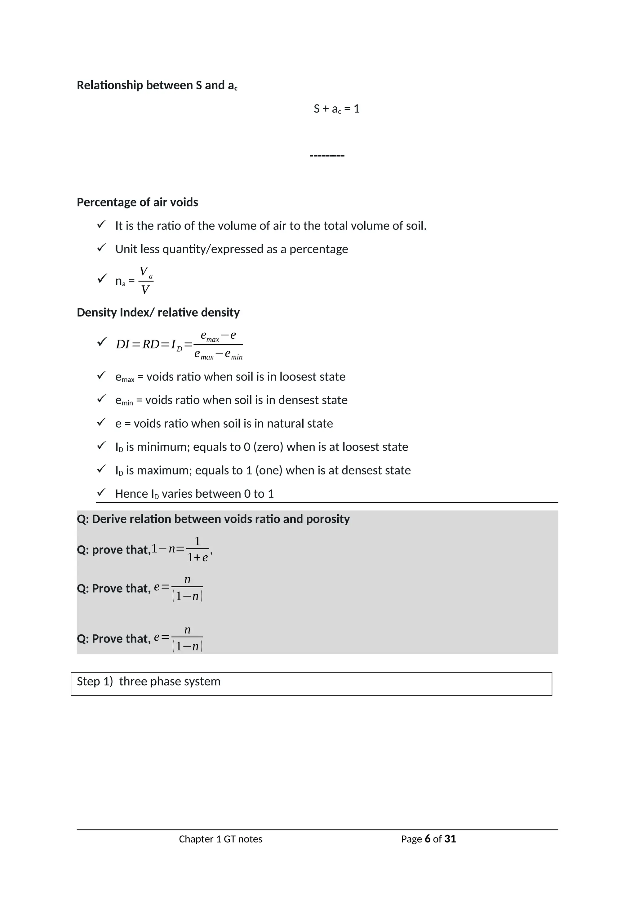
Water content
It is the ratio of mass of water in soil to mass of soil solids
Unit less quantity/ expressed as a percentage
w=
Mw
Ms
=
W w
Ws
Water content experiments formulae
Oven drying formula, w=
M−Ms
M s
Pycnometer method, w=
[M2−M1
M3−M4
×(G−1
G )−1
]×100
Where, M1 is mass of empty pycnometer, M2 is mass of pycnometer + most
soil, M3 is mass of pycnometer + most soil + water, M4 is mass of pycnometer
+water only, G is specific gravity
Specific gravity
It is the ratio of density of soil solid to density of water at standard temperature.
Unit less quantity/ expressed as a decimal
G=
ρsoilsolids
ρwater
=
ρs
ρw
Apparent/mass/ bulk Specific gravity
It is the ratio of density of soil to density of water at standard temperature.
Unit less quantity/ expressed as a decimal
Chapter 1 GT notes Page 4 of 31](https://image.slidesharecdn.com/chapter1-indexproperties-2-250118082727-920585c0/75/Chapter-1-index-properties-2-presentation-and-question-answer-4-2048.jpg)
![γ=
W w
V
+γd
Multiply-divide by Ws as shown below,
γ=
W w
V
×
W s
W s
+γd
From basic formula,
γ=
W w
W s
×
W s
V
+γd=w×γd+γd
Taking common factors
γ=(w+1)γd
Rearranging
γd=
γ
1+w
Proved
Q: Derive relation between degree of saturation, voids ratio, bulk unit weight and specific
gravity
Q: prove that, γ=
[G+eS]γw
1+e
Q: prove that,
γ
sat=¿
[G+e]γw
1+e
¿
Q: prove that,
γ
d=¿
Gγw
1+e
¿
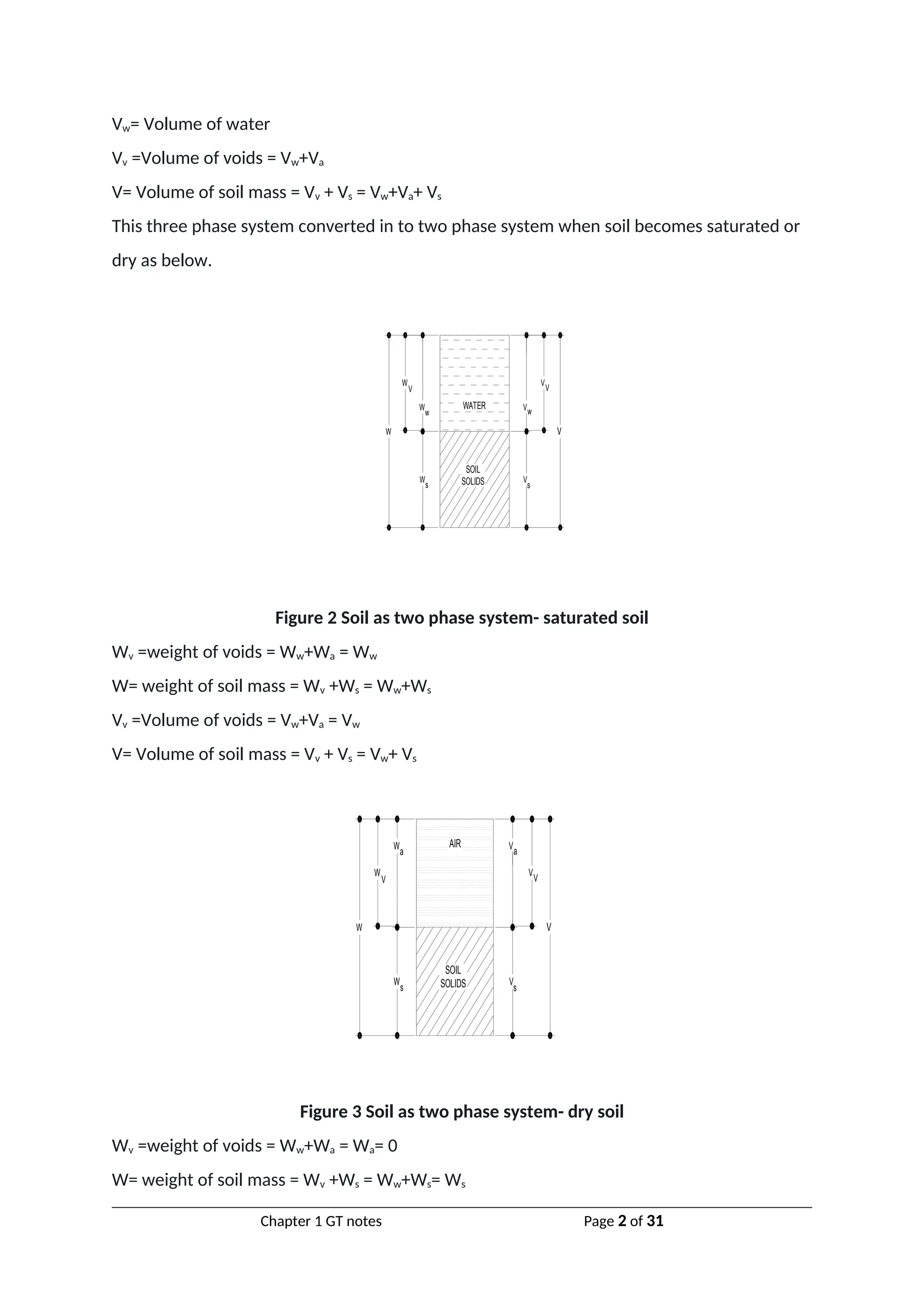
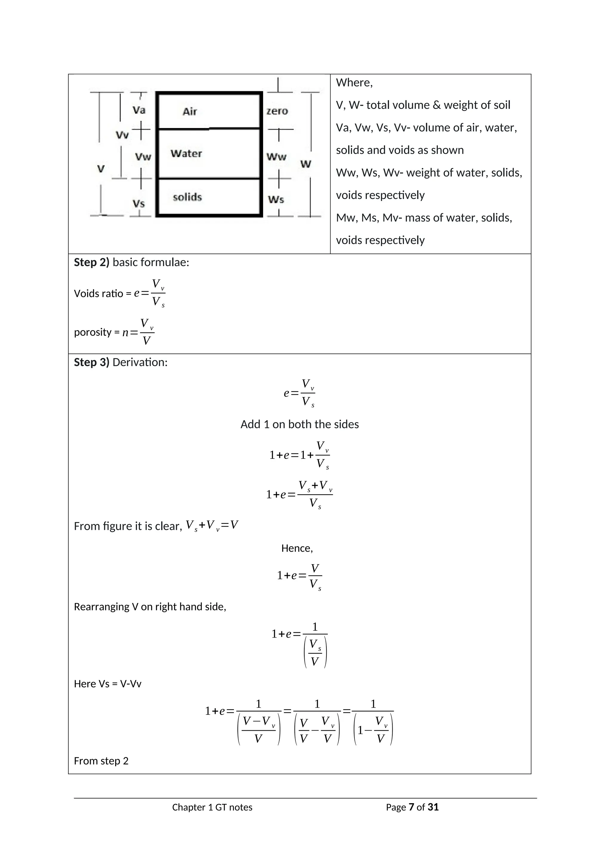
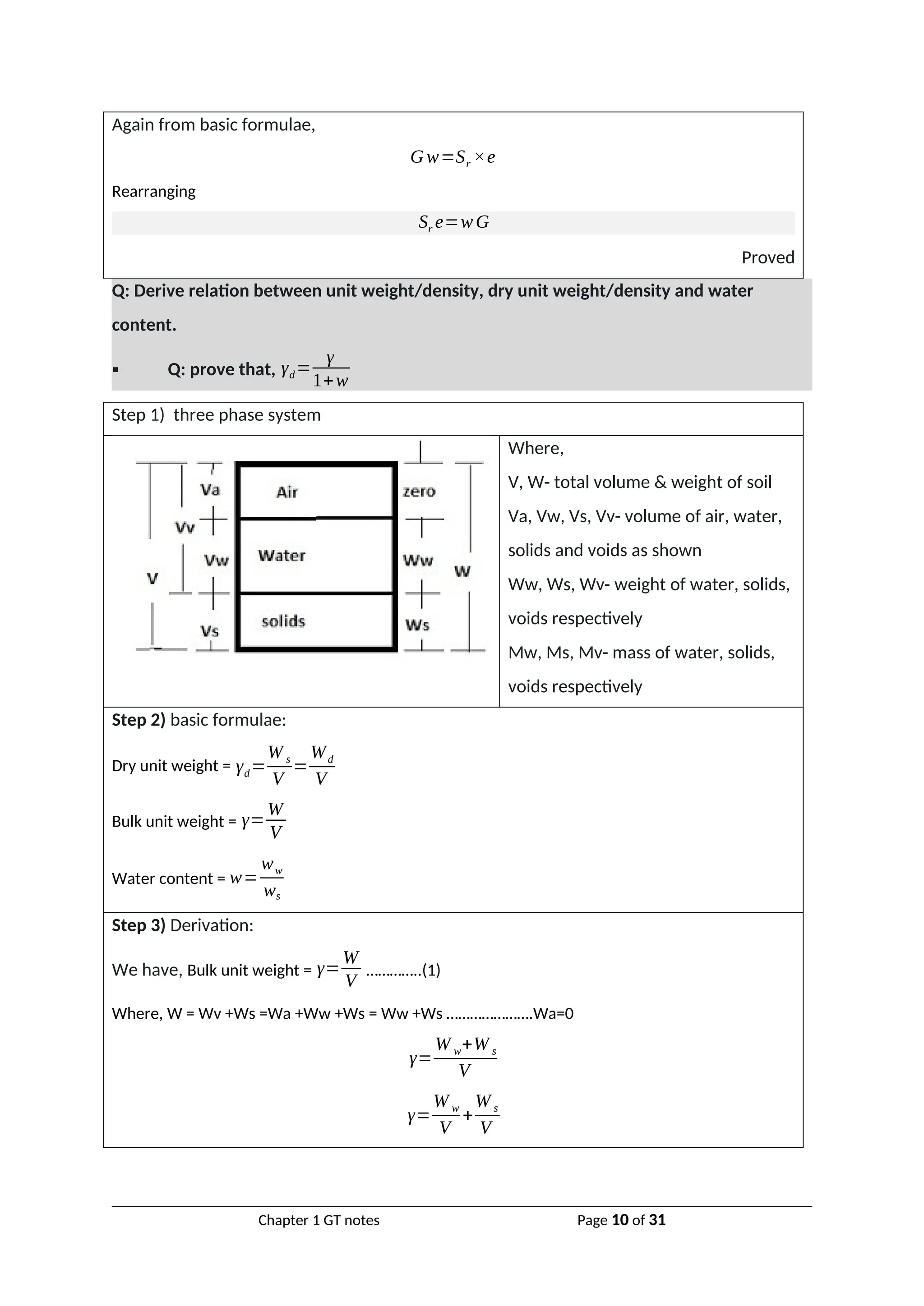
Step 1) three phase system
Where,
V, W- total volume & weight of soil
Va, Vw, Vs, Vv- volume of air, water,
solids and voids as shown
Ww, Ws, Wv- weight of water, solids,
voids respectively
Mw, Ms, Mv- mass of water, solids,
voids respectively
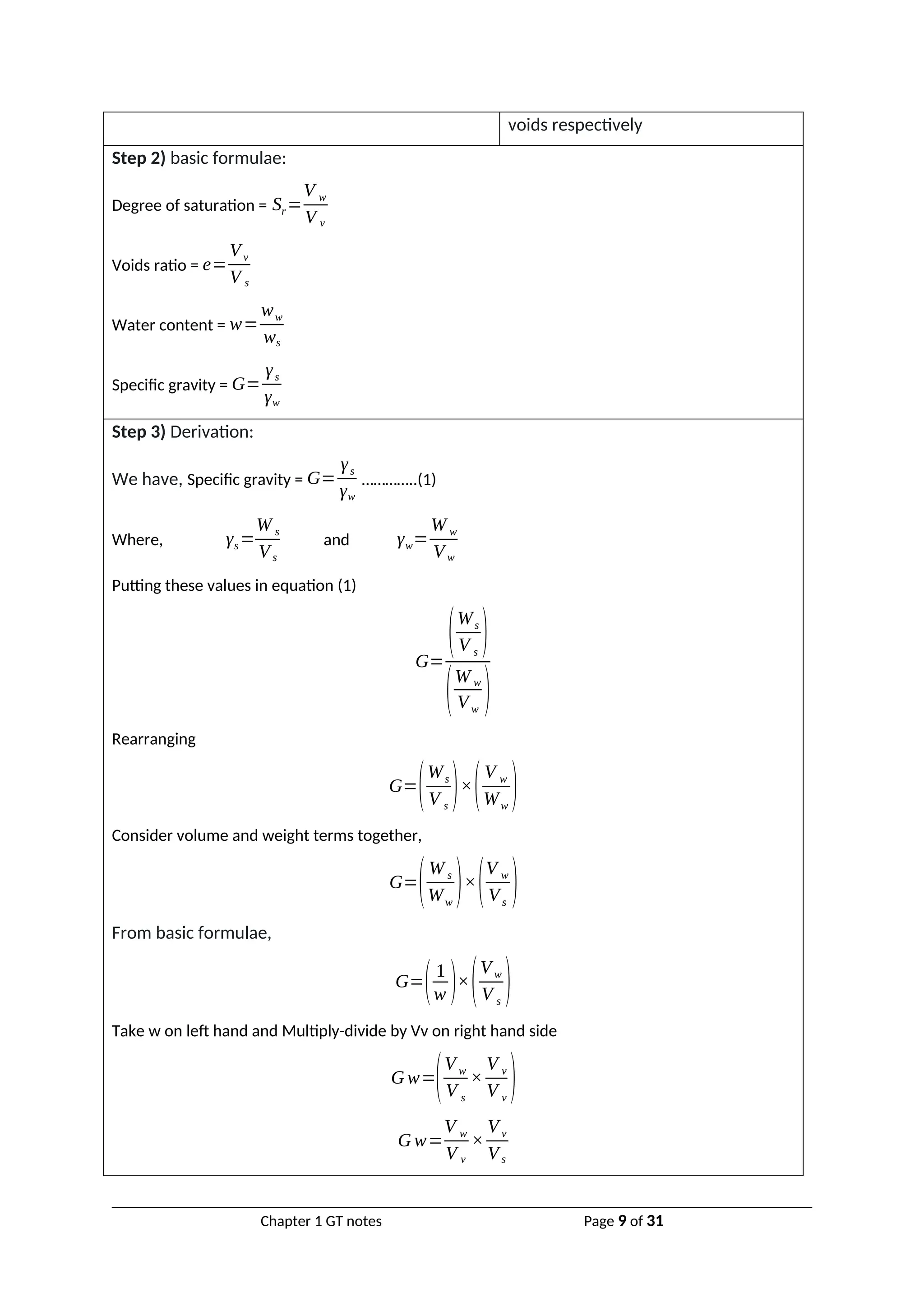
Step 2) basic formulae:
Degree of saturation = Sr=
V w
V v
Chapter 1 GT notes Page 11 of 31](https://image.slidesharecdn.com/chapter1-indexproperties-2-250118082727-920585c0/75/Chapter-1-index-properties-2-presentation-and-question-answer-11-2048.jpg)
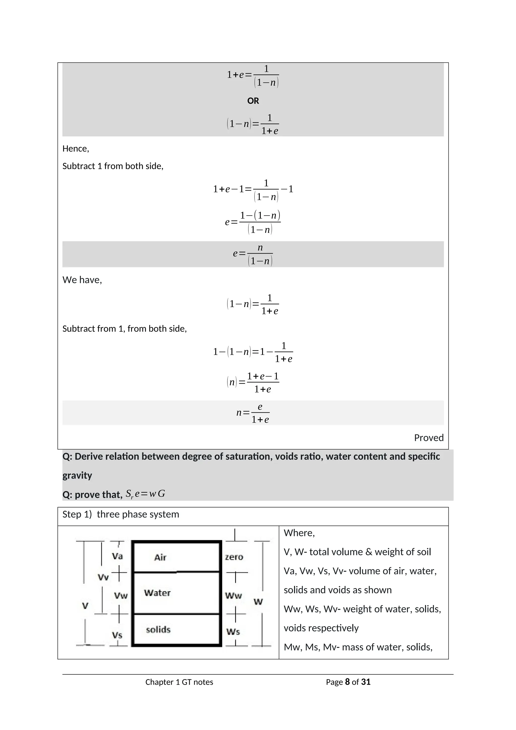
![Voids ratio = e=
Vv
V s
Water content = w=
ww
ws
Specific gravity = G=
γs
γw
Dry unit weight = γd=
W s
V
=
Wd
V
Bulk unit weight = γ=
W
V
Saturated unit weight = γsat =
W sat
V
Step 3) Derivation:
We have, Bulk unit weight = γ=
W
V
…………..(1)
Where, W = Wv +Ws =Wa +Ww +Ws = Ww +Ws ………………….Wa=0
γ=
W w+W s
VV +V s
Taking common from denominator (RHS)
γ=
Ww +W s
(VV
Vs
+1
)V s
=
W w+Ws
(e+1)Vs
γ=
1
(1+e) [Ww +W s
V s
]=
1
(1+e)[Ww
V s
+
W s
Vs
]
γ=
1
(1+e) [Ww
Vs
+γs
]
Multiply-divide by Vv&Vw as shown below,
γ=
1
(1+e) [Ww
Vs
×
V v
V v
×
Vw
Vw
+γs
]
γ=
1
(1+e) [Ww
Vw
×
V v
Vs
×
Vw
Vv
+γs
]
γ=
1
(1+e)
[γw ×e ×Sr+γs]
Taking common γw from bracket
Chapter 1 GT notes Page 12 of 31](https://image.slidesharecdn.com/chapter1-indexproperties-2-250118082727-920585c0/75/Chapter-1-index-properties-2-presentation-and-question-answer-12-2048.jpg)
![γ=
1
(1+e) [e×Sr+
γs
γw
]γw
Then,
γ=
1
(1+e)
[e ×Sr+G ]γw
Rearrenging
γ=
(G+e Sr)γw
(1+e)
If Soil is dry, Sr = 0 and γ become γd
γd=
G γw
(1+e)
If Soil is saturated, Sr = 1 and γ become γsat
γd=
(G+e)γw
(1+e)
Proved
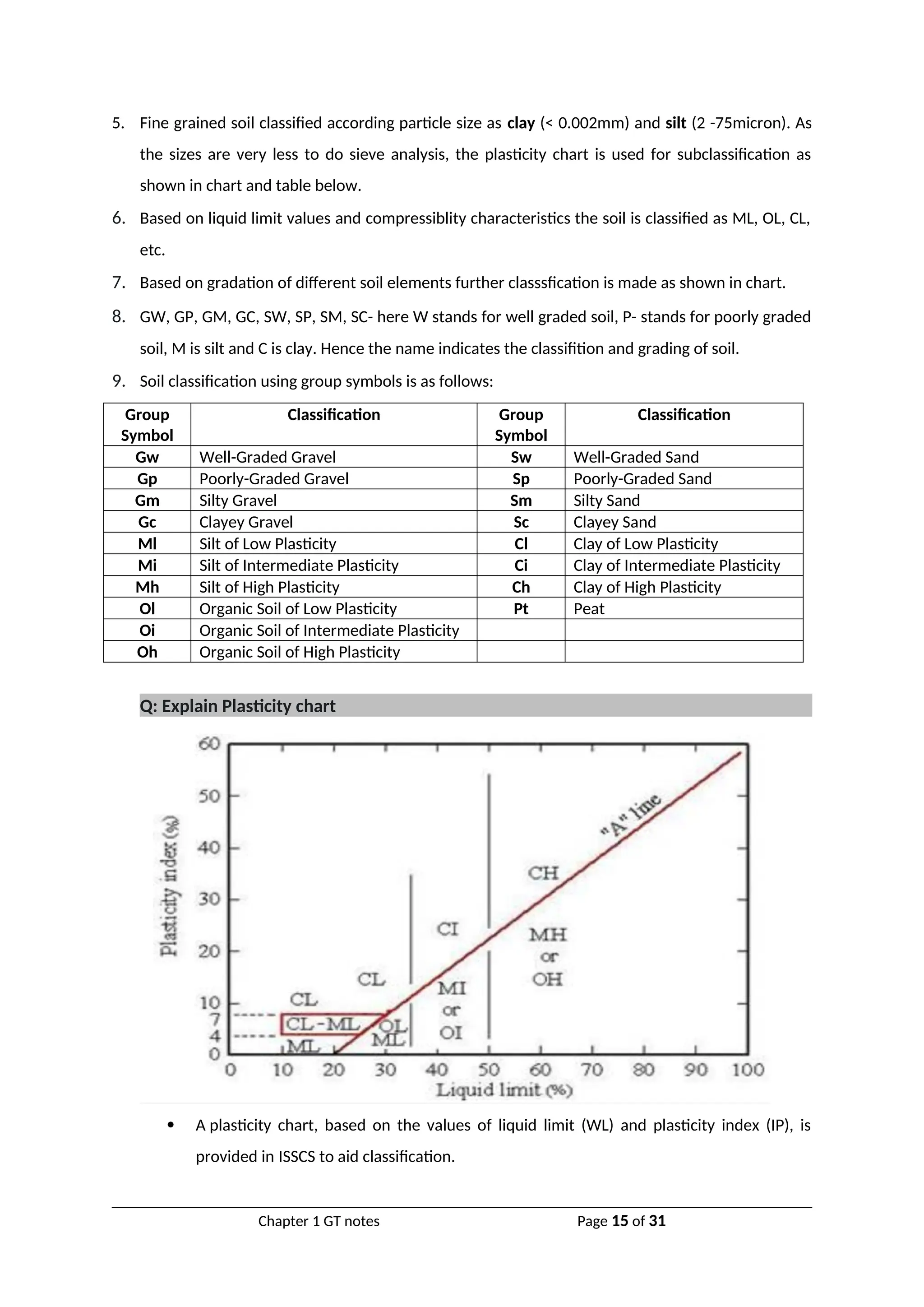
Q: Explain IS soil classification system (as per IS 1498-1970)
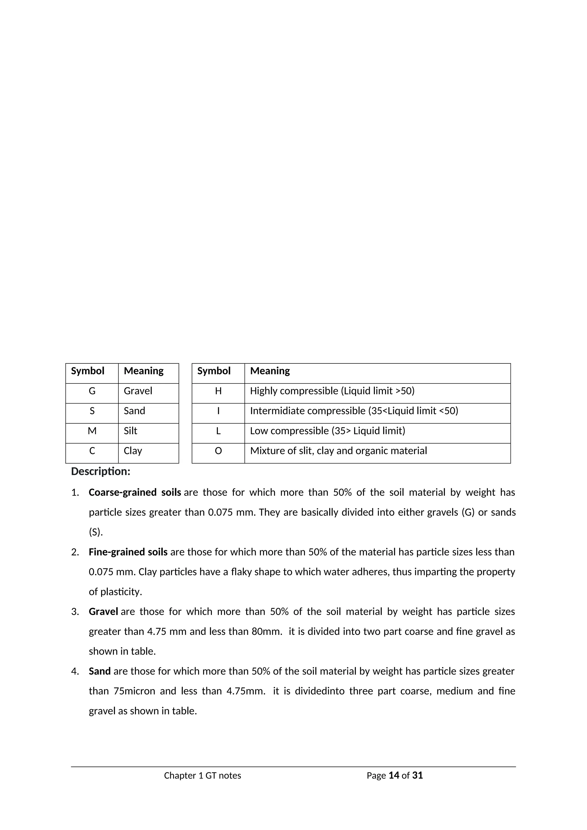
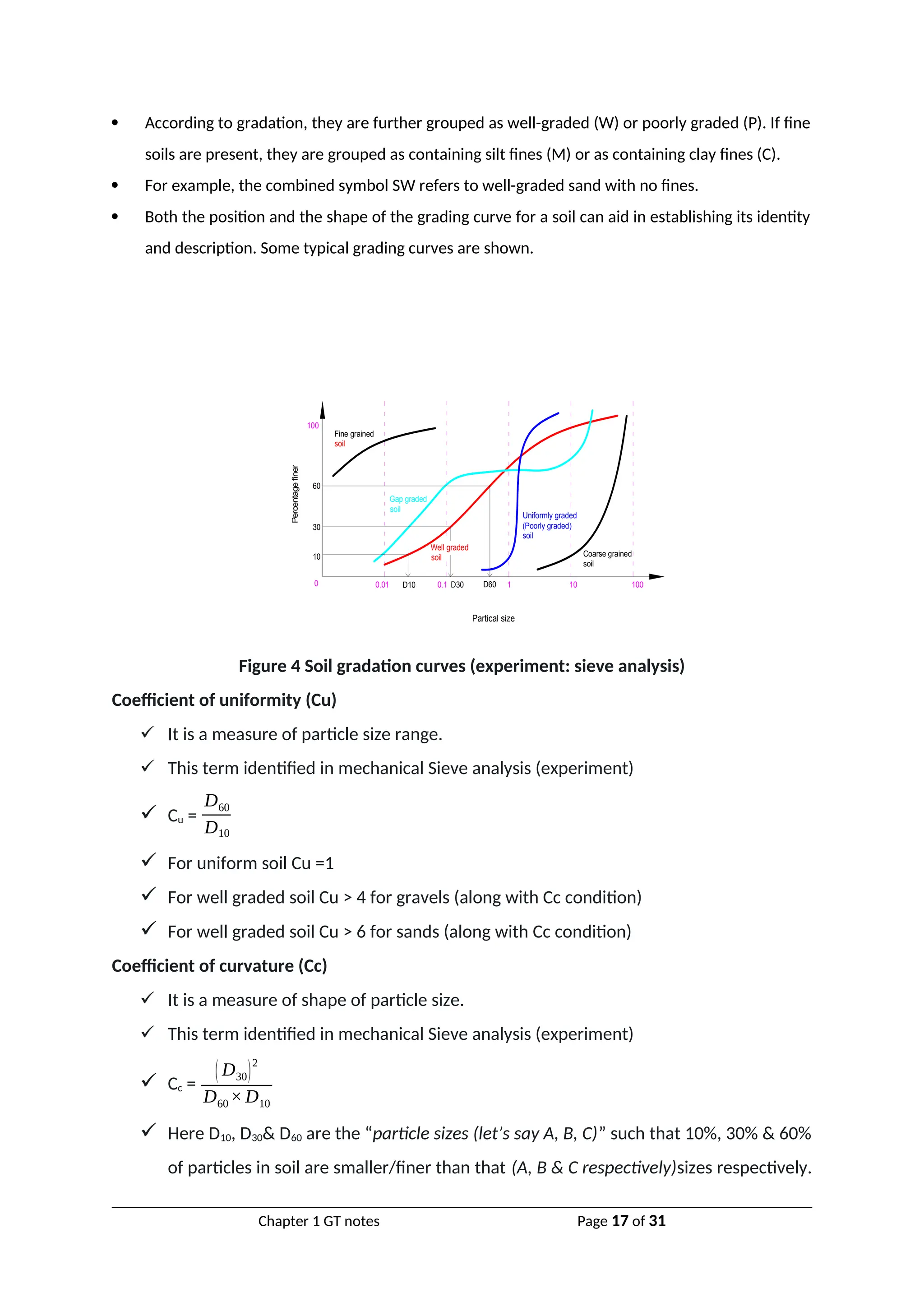
Classification Based on Grain Size:The range of particle sizes encountered in soils is very large: from
boulders with dimension of over 300 mm down to clay particles that are less than 0.002 mm. Some
clays contain particles less than 0.001 mm in size which behave as colloids, i.e. do not settle in water.
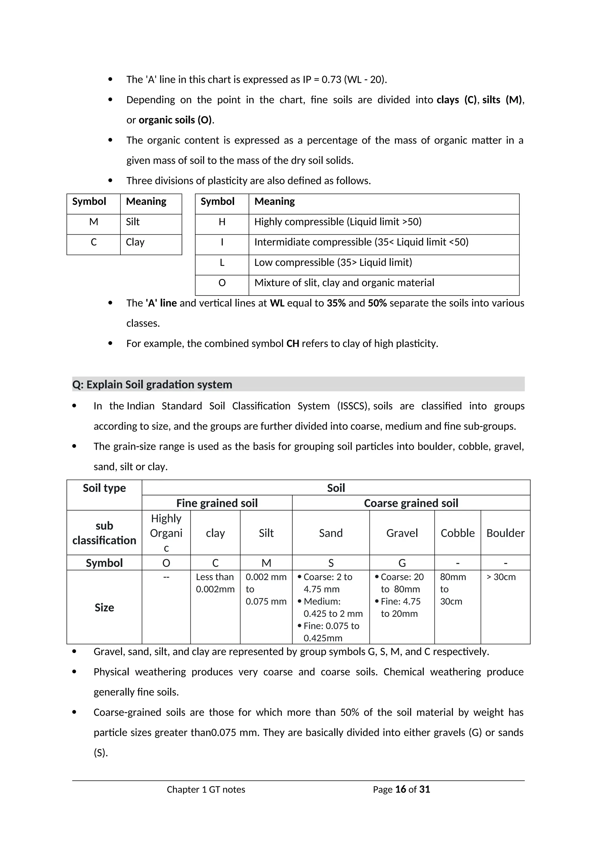
In the Indian Standard Soil Classification System (ISSCS), soils are classified into groups according to
size, and the groups are further divided into coarse, medium and fine sub-groups.
Soil type Soil
Fine grained soil Coarse grained soil
sub
classification
Highly
Organi
c
clay Silt Sand Gravel Cobble Boulder
Symbol O C M S G - -
Size
-- Less than
0.002mm
0.002 mm
to
0.075 mm
Coarse: 2 to
4.75 mm
Medium:
0.425 to 2 mm
Fine: 0.075 to
0.425mm
Coarse: 20
to 80mm
Fine: 4.75
to 20mm
80mm
to
30cm
> 30cm
Chapter 1 GT notes Page 13 of 31](https://image.slidesharecdn.com/chapter1-indexproperties-2-250118082727-920585c0/75/Chapter-1-index-properties-2-presentation-and-question-answer-13-2048.jpg)
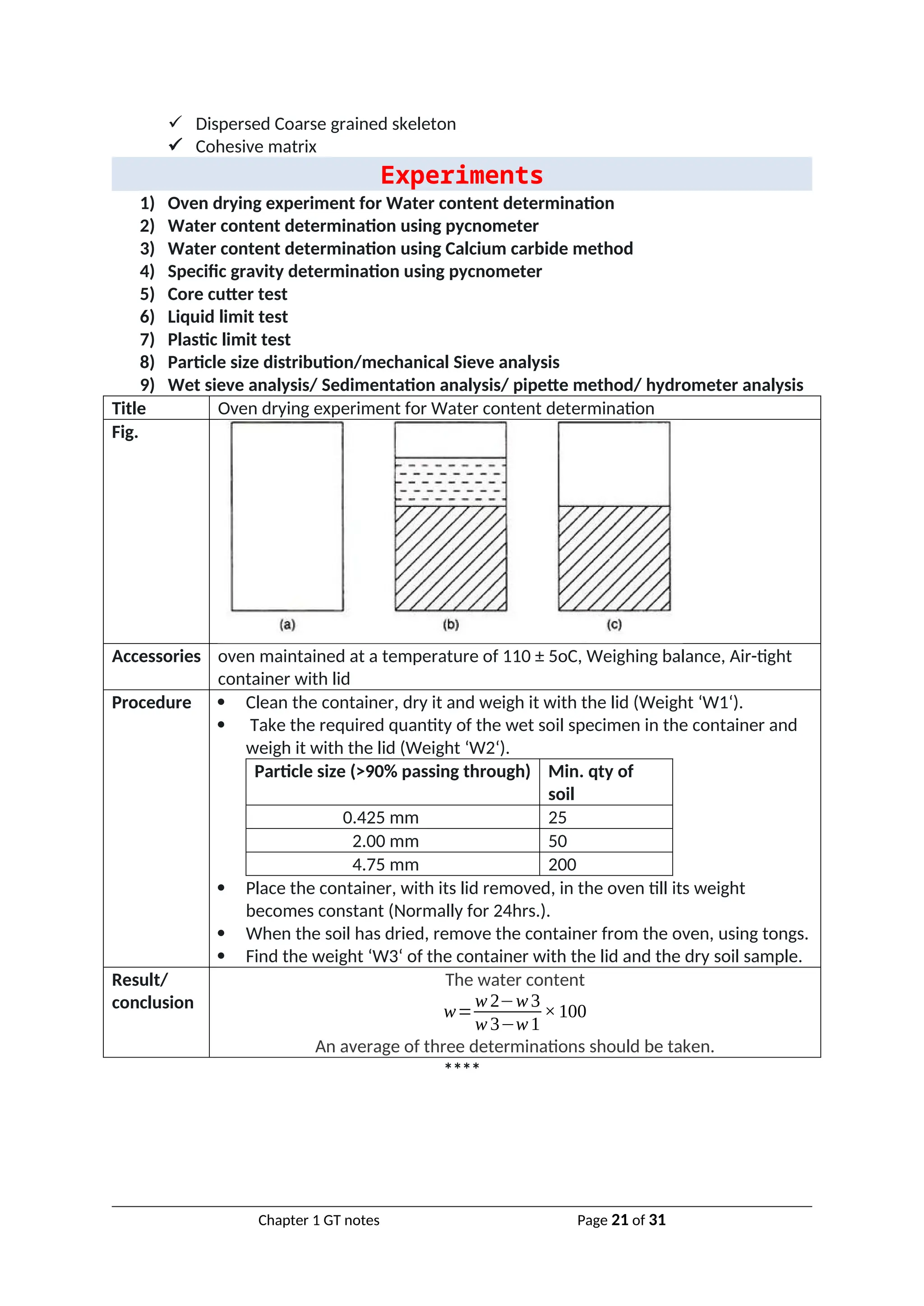
![Title Water content determination using pycnometer
Fig.
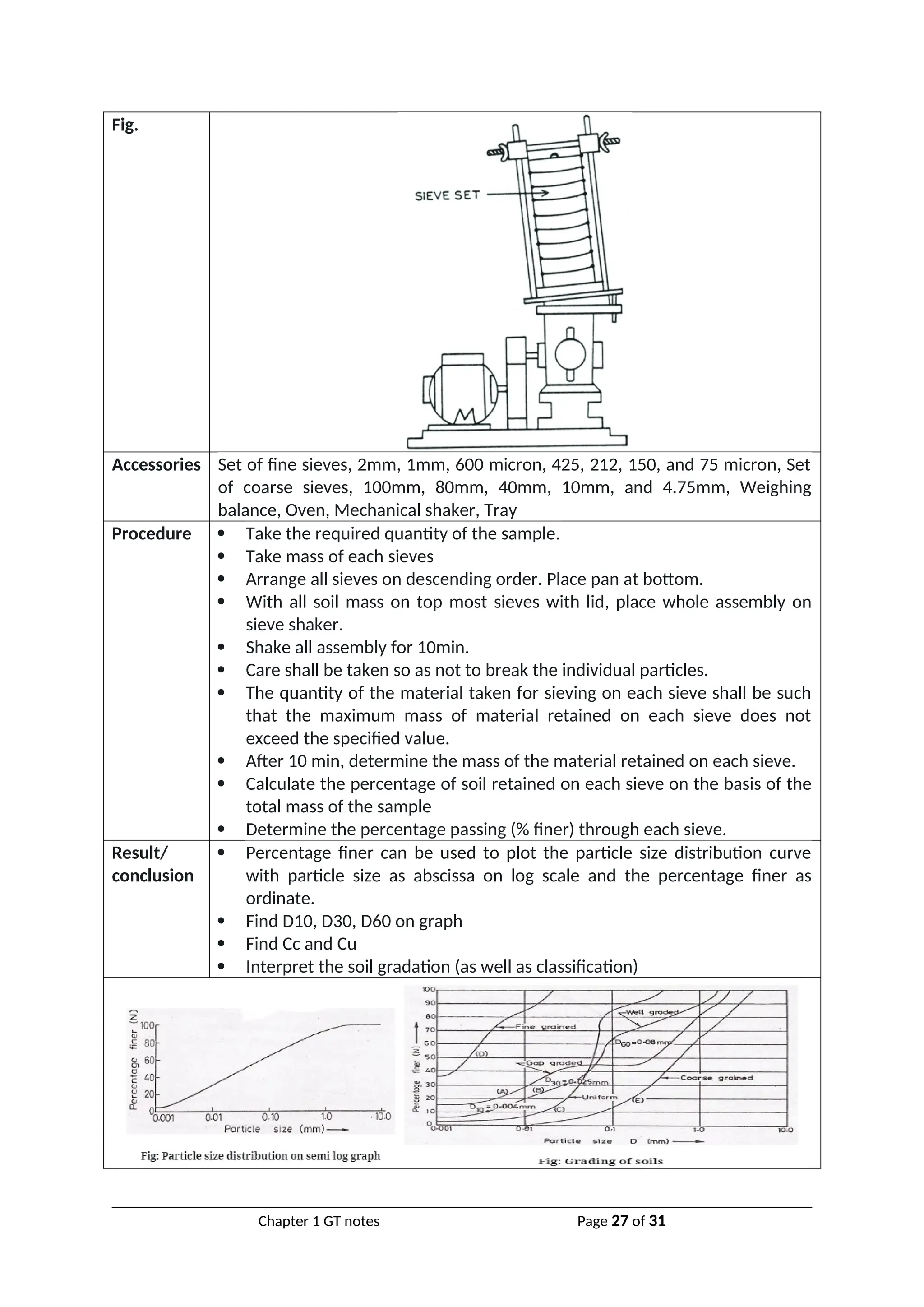
Accessories Pycnometer, Weighing balance with an accuracy of 1.0g, Glass rod
Procedure Wash, clean and dry the pycnometer and note down its mass (W1) along
with brass cap and washer using weighing balance with an accuracy of 1.0
g.
Now place a sample of wet soil about 200 to 400 g in pycnometer and
note down its mass (W2).
Then add water to the soil in the pycnometer to make it about half full.
Stir the soil using glass rod to remove air voids of the soil sample.
Add some more water and after eliminating the entrapped air stop stirring
and fix the brass cap.
More water is added through hole in brass cap until the water is flush with
the hole.
Now take the mass of pycnometer (W3).
Now empty and wash the pycnometer. Then fill it with only water and take
its mass (W4).
Result/
conclusion
The water content
w=
[(w 2– w 1
w3 – w 4 )(G−1
G )−1
]×100
An average of three determinations should be taken.
***
Title Water content determination using Calcium carbide method
Fig.
Accessories Metallic pressure vessel, with a clamp for sealing the cup, along with a gauge
calibrated in percentage water content, weighing balance, Scoop, for
measuring the absorbent, Steel balls – 3 steel balls of about 12.5mm dia. and
1 steel ball of 25mm dia., One bottle of the absorbent (Calcium Carbide)
Chapter 1 GT notes Page 22 of 31](https://image.slidesharecdn.com/chapter1-indexproperties-2-250118082727-920585c0/75/Chapter-1-index-properties-2-presentation-and-question-answer-22-2048.jpg)
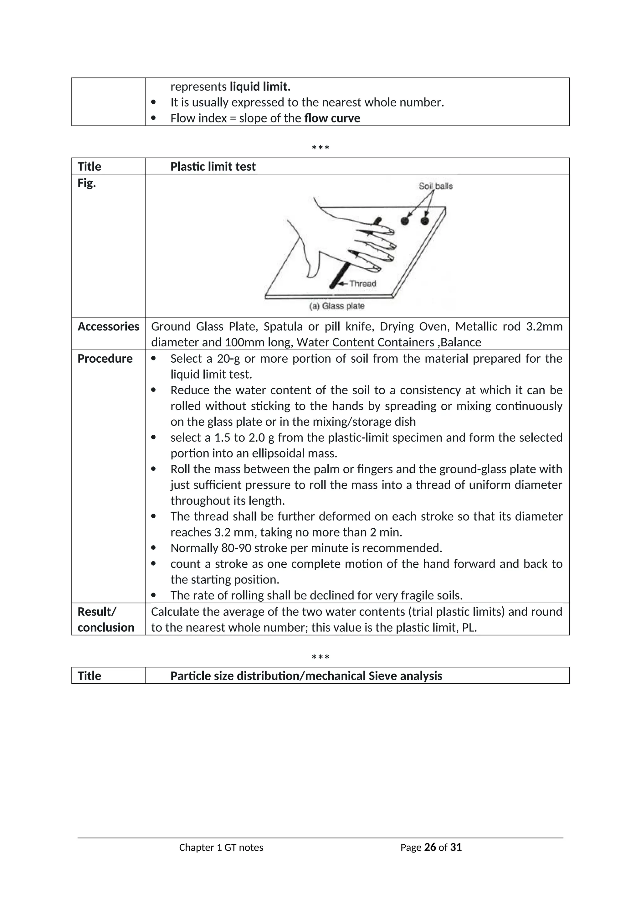
![Procedure Set up the balance, place the sample in the pan till the mark on the
balance arm matches with the index mark.
Check that the cup and the body are clean.
Hold the body horizontally and gently deposit the levelled, scoop-full of
the absorbent (Calcium Carbide) inside the chamber.
Transfer the weighed soil from the pan to the cup.
Hold cup and chamber horizontally, bringing them together without
disturbing the sample and the absorbent.
Clamp the cup tightly into place. If the sample is bulky, reverse the above
placement, that is, put the sample in the chamber and the absorbent in
the cup.
In case of clayey soils, place all the 4 steel balls (3 smaller and 1 bigger) in
the body along with the absorbent.
Shake the unit up and down vigorously in this position for about 15
seconds.
Hold the unit horizontally, rotating it for 10 seconds, so that the balls roll
around the inner circumference of the body.
Rest for 20 seconds.
Repeat the above cycle until the pressure gauge reading is constant and
note the reading. Usually it takes 4 to 8 minutes to achieve constant
reading. This is the water content (m) obtained on wet mass basis.
Finally, release the pressure slowly by opening the clamp screw and taking
the cup out, empty the contents and clean the instrument with a brush.
Result/
conclusion
The water content on dry mass basis,
w=m/[100-m] * 100%
*****
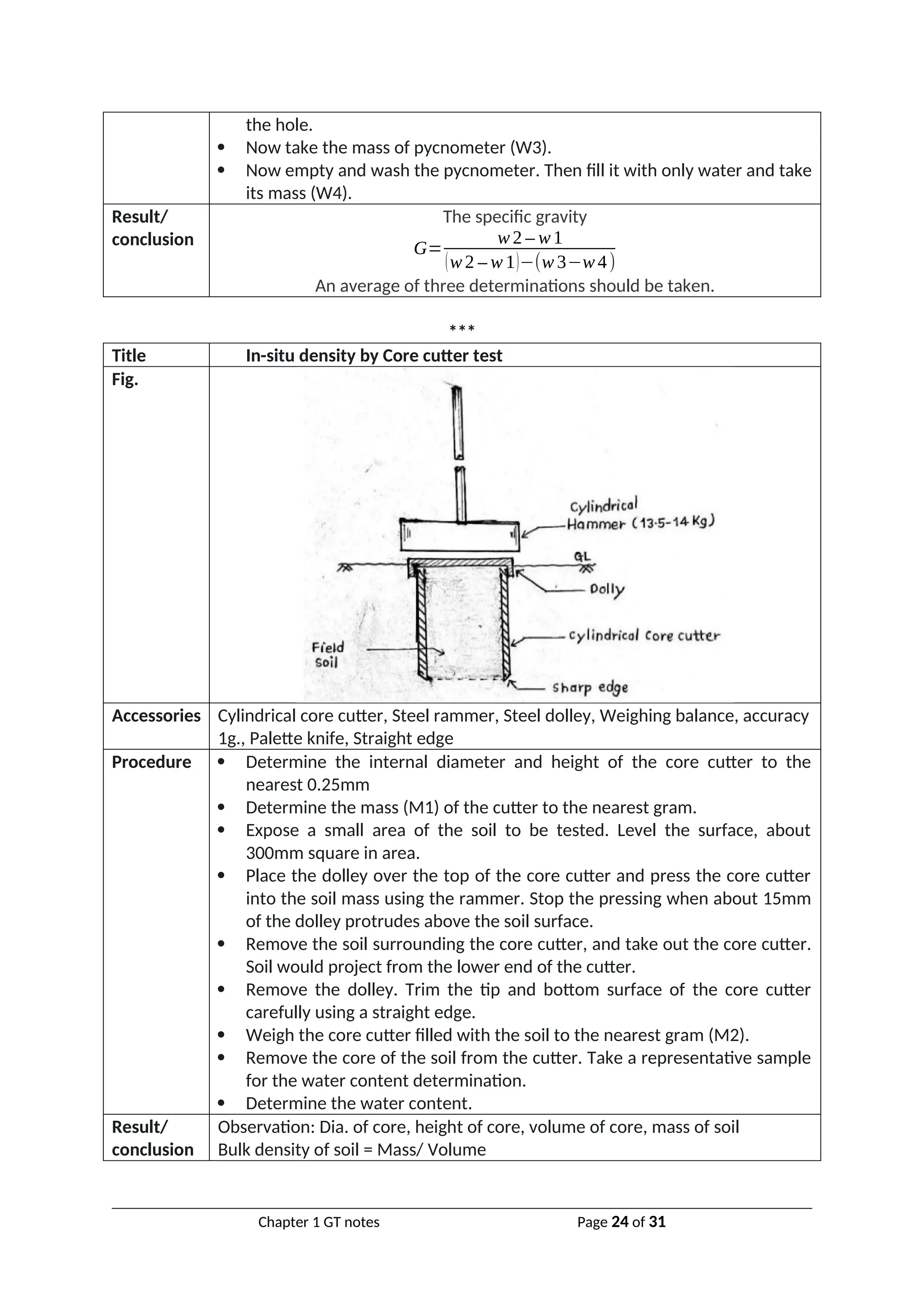
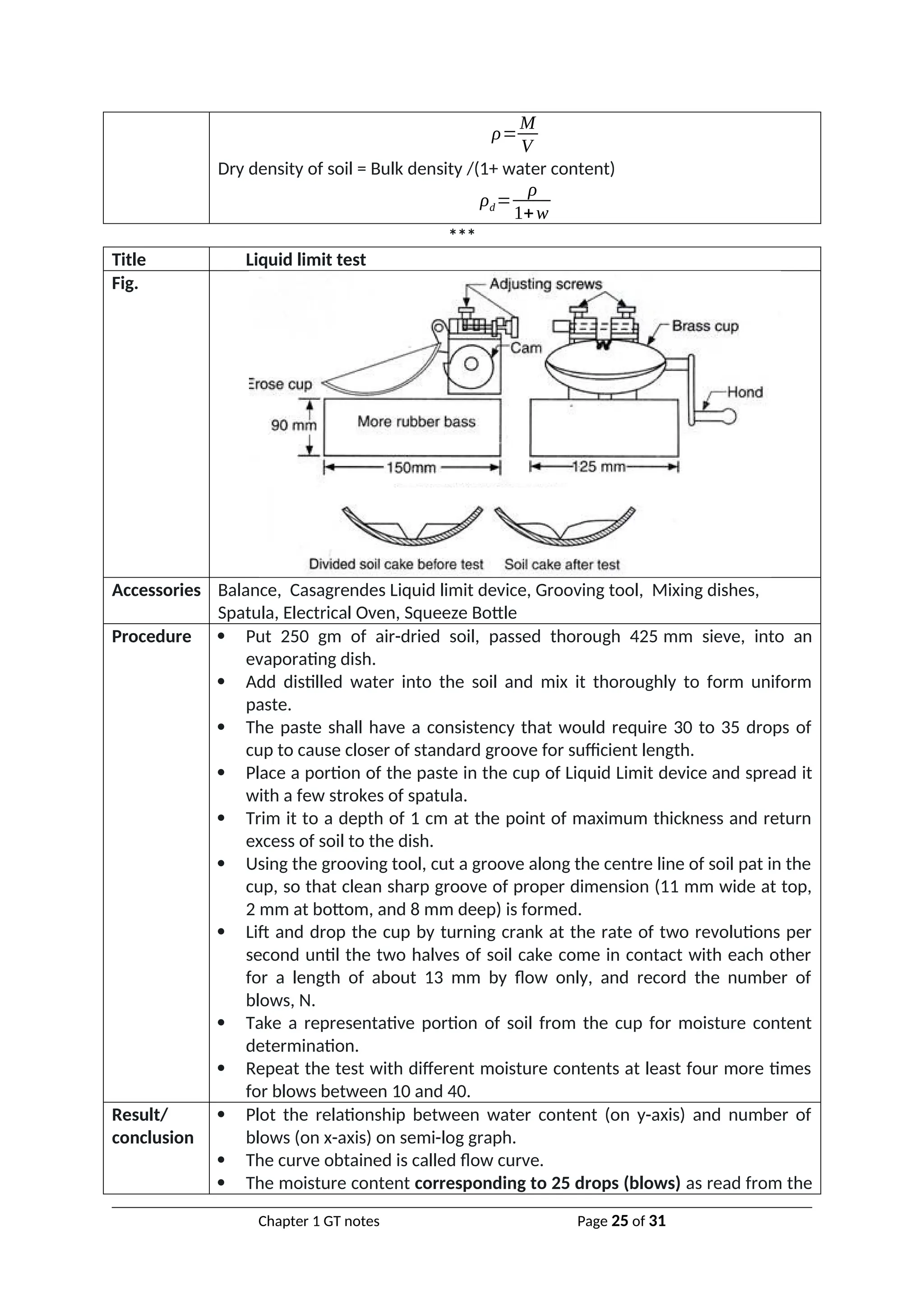
Title Specific gravity determination using pycnometer
Fig.
Accessories Pycnometer, Weighing balance with an accuracy of 1.0g, Glass rod
Procedure Wash, clean and dry the pycnometer and note down its mass (W1) along
with brass cap and washer using weighing balance with an accuracy of 1.0
g.
Now place a sample of dry soil about 200 to 400 g in pycnometer and note
down its mass (W2).
Then add water to the soil in the pycnometer to make it about half full.
Stir the soil using glass rod to remove air voids of the soil sample.
Add some more water and after eliminating the entrapped air stop stirring
and fix the brass cap.
More water is added through hole in brass cap until the water is flush with
Chapter 1 GT notes Page 23 of 31](https://image.slidesharecdn.com/chapter1-indexproperties-2-250118082727-920585c0/75/Chapter-1-index-properties-2-presentation-and-question-answer-23-2048.jpg)
![***
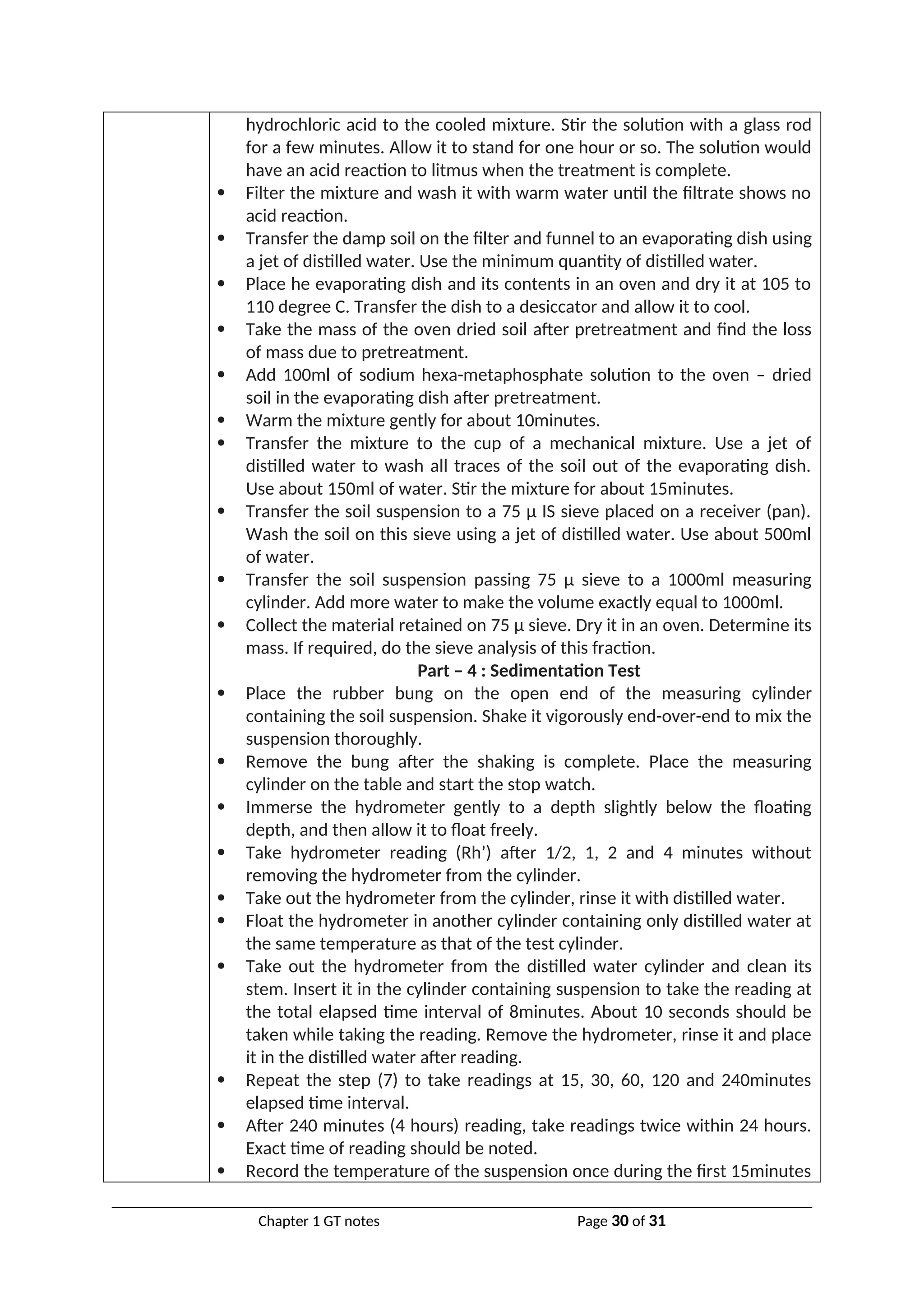
Title Hydrometer analysis
Fig.
Accessories
1. Hydrometer, Glass measuring cylinder (jar), 1000ml, Rubber bung for the
cylinder (jar), Mechanical stirrer, Weighing balance, accuracy 0.01g, Oven,
Deflocculating agent., Desiccator, Evaporating dish, Conical flask or beaker,
1000ml, Stop watch, Wash bottle, Thermometer, Water bath, 75 µ Sieve, Scale
Procedure The particle size (D) is given by:
D=M
√He
t
M=
[ 0.3η
g(G−1) ρw
]
In which,
n = viscosity of water in poise,
G = specific gravity of solids,
Pw = density of water (gm/ml); ,
He= effective depth,
t= time in minutes at which observation is taken, reckoned with respect to
the beginning of sedimentation.
The percentage finer than the size D is given by
N=
[ G
G−1]×
R
Ms
×100
Where,
R= corrected hydrometer reading, Ms= mass of dry soil in 1000ml
suspension.
Stoke’s Law,
ν=
D
2
γw (Gs−GL)
18η
Procedure of Hydrometer Test
Part – 1: Calibration of Hydrometer
Take about 800ml of water in one measuring cylinder. Place the cylinder
on a table and observe the initial reading.
Immerse the hydrometer in the cylinder. Take the reading after the
Chapter 1 GT notes Page 28 of 31](https://image.slidesharecdn.com/chapter1-indexproperties-2-250118082727-920585c0/75/Chapter-1-index-properties-2-presentation-and-question-answer-28-2048.jpg)
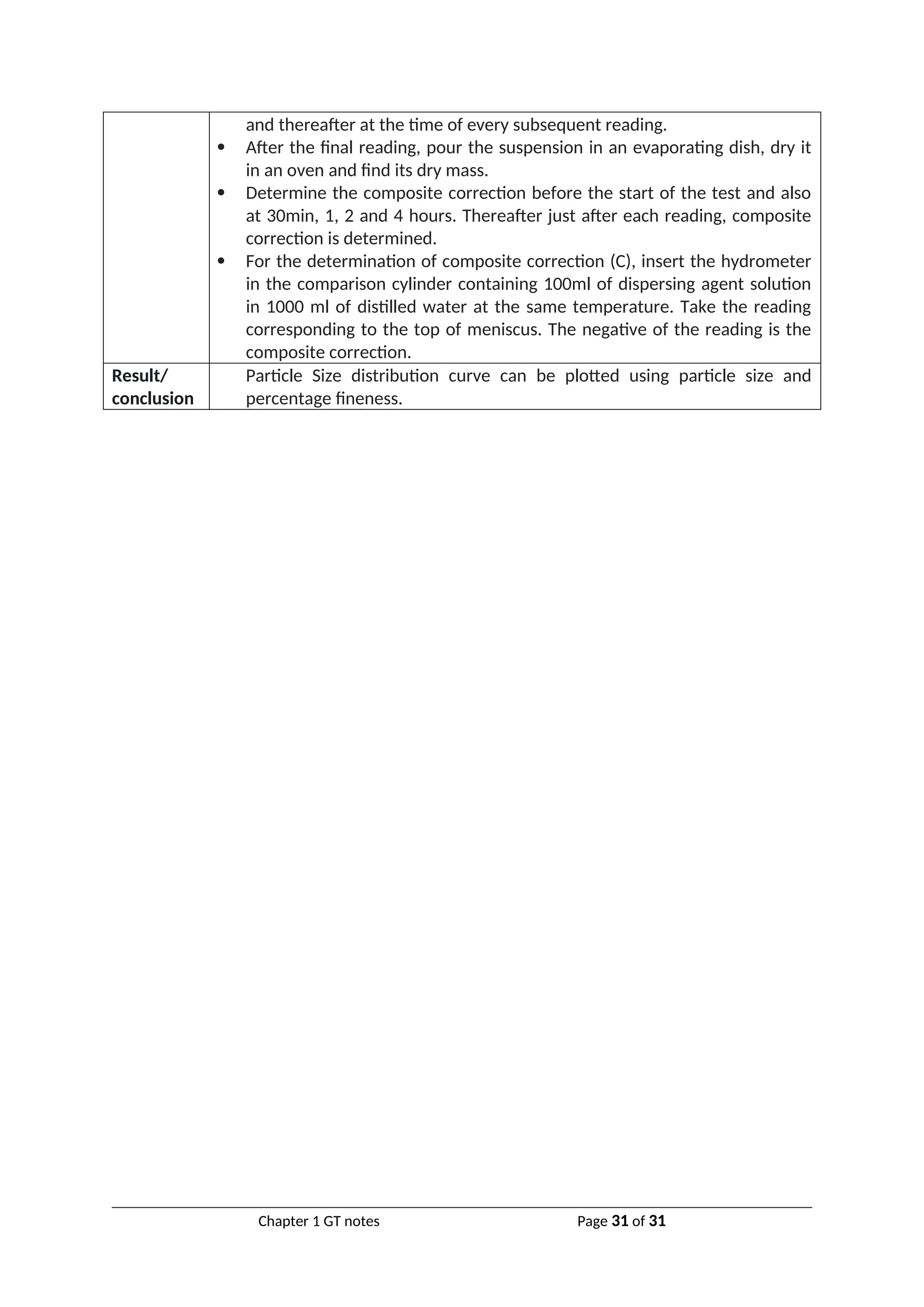
![immersion.
Determine the volume of the hydrometer (VH) which is equal to the
difference between the final and initial readings. Alternatively weigh the
hydrometer to the nearest 0.1g. The volume of the hydrometer in ml is
approximately equal to its mass in grams.
Determine the area of cross section (A) of the cylinder. It is equal to the
volume indicated between any two graduations divided by the distance
between them. The distance is measured with an accurate scale.
Measure the distance (H) between the neck and the bottom of the bulb.
Record it as the height of the bulb (h).
Measure the distance (H) between the neck to each marks on the
hydrometer (Rh).
Determine the effective depth (He), corresponding to each of the mark
(Rh) as
[Note: The factor VH/A should not be considered when the hydrometer is
not taken out when taking readings after the start of the sedimentation at
½, 1, 2, and 4 minutes.]
Draw a calibration curve between He and Rh. Alternatively, prepare a
table between He and Rh. The curve may be used for finding the effective
depth He corresponding to reading Rh.
Part – 2 : Meniscus Correction
Insert the hydrometer in the measuring cylinder containing about 700ml
of water.
Take the readings of the hydrometer at the top and at the bottom of the
meniscus.
Determine the meniscus correction, which is equal to the difference
between the two readings.
The meniscus correction Cm is positive and is constant for the
hydrometer.
The observed hydrometer reading Rh’ is corrected to obtain the corrected
hydrometer reading Rh as
Part – 3 : Pretreatment and Dispersion
Weigh accurately, to the nearest 0.01g about 50g air-dried soil sample
passing 2mm IS sieve, obtained by riffling from the air-dried sample
passing 4.75mm IS sieve. Place the sample in a wide mouthed conical
flask.
Add about 150ml of hydrogen peroxide to the soil sample in the flask. Stir
it gently with a glass rod for a few minutes.
Cover the flask with a glass plate and leave it to stand overnight.
Heat the mixture in the conical flask gently after keeping it in an
evaporating dish. Stir the contents periodically. When vigorous frothing
subsides, the reaction is complete. Reduce the volume to 50ml by boiling.
Stop heating and cool the contents.
If the soil contains insoluble calcium compounds, add about 50ml of
Chapter 1 GT notes Page 29 of 31](https://image.slidesharecdn.com/chapter1-indexproperties-2-250118082727-920585c0/75/Chapter-1-index-properties-2-presentation-and-question-answer-29-2048.jpg)


![Saturated Unit Weight
It is the ratio of saturated weight of soil to volume of soil
Symbol γsat
Submerged Unit Weight
It is the ratio of submerged weight of soil to volume of soil
Symbol γ'
γ'
=γsat −γw=γsat −9.81…….unit weight of water γw=9.81g/cc
Relation between density and unit weight
γ=ρ×g=ρ×9.81
---------
Water content
It is the ratio of mass of water in soil to mass of soil solids
Unit less quantity/ expressed as a percentage
w=
Mw
Ms
=
W w
Ws
Water content experiments formulae
Oven drying formula, w=
M−Ms
M s
Pycnometer method, w=
[M2−M1
M3−M4
×(G−1
G )−1
]×100
Where, M1 is mass of empty pycnometer, M2 is mass of pycnometer + most
soil, M3 is mass of pycnometer + most soil + water, M4 is mass of pycnometer
+water only, G is specific gravity
Specific gravity
It is the ratio of density of soil solid to density of water at standard temperature.
Unit less quantity/ expressed as a decimal
G=
ρsoilsolids
ρwater
=
ρs
ρw
Apparent/mass/ bulk Specific gravity
It is the ratio of density of soil to density of water at standard temperature.
Unit less quantity/ expressed as a decimal
Chapter 1 GT notes Page 4 of 31](https://crownmelresort.com/image.slidesharecdn.com/chapter1-indexproperties-2-250118082727-920585c0/75/Chapter-1-index-properties-2-presentation-and-question-answer-4-2048.jpg)


![γ=
W w
V
+γd
Multiply-divide by Ws as shown below,
γ=
W w
V
×
W s
W s
+γd
From basic formula,
γ=
W w
W s
×
W s
V
+γd=w×γd+γd
Taking common factors
γ=(w+1)γd
Rearranging
γd=
γ
1+w
Proved
Q: Derive relation between degree of saturation, voids ratio, bulk unit weight and specific
gravity
Q: prove that, γ=
[G+eS]γw
1+e
Q: prove that,
γ
sat=¿
[G+e]γw
1+e
¿
Q: prove that,
γ
d=¿
Gγw
1+e
¿
Step 1) three phase system
Where,
V, W- total volume & weight of soil
Va, Vw, Vs, Vv- volume of air, water,
solids and voids as shown
Ww, Ws, Wv- weight of water, solids,
voids respectively
Mw, Ms, Mv- mass of water, solids,
voids respectively
Step 2) basic formulae:
Degree of saturation = Sr=
V w
V v
Chapter 1 GT notes Page 11 of 31](https://crownmelresort.com/image.slidesharecdn.com/chapter1-indexproperties-2-250118082727-920585c0/75/Chapter-1-index-properties-2-presentation-and-question-answer-11-2048.jpg)
![Voids ratio = e=
Vv
V s
Water content = w=
ww
ws
Specific gravity = G=
γs
γw
Dry unit weight = γd=
W s
V
=
Wd
V
Bulk unit weight = γ=
W
V
Saturated unit weight = γsat =
W sat
V
Step 3) Derivation:
We have, Bulk unit weight = γ=
W
V
…………..(1)
Where, W = Wv +Ws =Wa +Ww +Ws = Ww +Ws ………………….Wa=0
γ=
W w+W s
VV +V s
Taking common from denominator (RHS)
γ=
Ww +W s
(VV
Vs
+1
)V s
=
W w+Ws
(e+1)Vs
γ=
1
(1+e) [Ww +W s
V s
]=
1
(1+e)[Ww
V s
+
W s
Vs
]
γ=
1
(1+e) [Ww
Vs
+γs
]
Multiply-divide by Vv&Vw as shown below,
γ=
1
(1+e) [Ww
Vs
×
V v
V v
×
Vw
Vw
+γs
]
γ=
1
(1+e) [Ww
Vw
×
V v
Vs
×
Vw
Vv
+γs
]
γ=
1
(1+e)
[γw ×e ×Sr+γs]
Taking common γw from bracket
Chapter 1 GT notes Page 12 of 31](https://crownmelresort.com/image.slidesharecdn.com/chapter1-indexproperties-2-250118082727-920585c0/75/Chapter-1-index-properties-2-presentation-and-question-answer-12-2048.jpg)
![γ=
1
(1+e) [e×Sr+
γs
γw
]γw
Then,
γ=
1
(1+e)
[e ×Sr+G ]γw
Rearrenging
γ=
(G+e Sr)γw
(1+e)
If Soil is dry, Sr = 0 and γ become γd
γd=
G γw
(1+e)
If Soil is saturated, Sr = 1 and γ become γsat
γd=
(G+e)γw
(1+e)
Proved
Q: Explain IS soil classification system (as per IS 1498-1970)
Classification Based on Grain Size:The range of particle sizes encountered in soils is very large: from
boulders with dimension of over 300 mm down to clay particles that are less than 0.002 mm. Some
clays contain particles less than 0.001 mm in size which behave as colloids, i.e. do not settle in water.
In the Indian Standard Soil Classification System (ISSCS), soils are classified into groups according to
size, and the groups are further divided into coarse, medium and fine sub-groups.
Soil type Soil
Fine grained soil Coarse grained soil
sub
classification
Highly
Organi
c
clay Silt Sand Gravel Cobble Boulder
Symbol O C M S G - -
Size
-- Less than
0.002mm
0.002 mm
to
0.075 mm
Coarse: 2 to
4.75 mm
Medium:
0.425 to 2 mm
Fine: 0.075 to
0.425mm
Coarse: 20
to 80mm
Fine: 4.75
to 20mm
80mm
to
30cm
> 30cm
Chapter 1 GT notes Page 13 of 31](https://crownmelresort.com/image.slidesharecdn.com/chapter1-indexproperties-2-250118082727-920585c0/75/Chapter-1-index-properties-2-presentation-and-question-answer-13-2048.jpg)


![Title Water content determination using pycnometer
Fig.
Accessories Pycnometer, Weighing balance with an accuracy of 1.0g, Glass rod
Procedure Wash, clean and dry the pycnometer and note down its mass (W1) along
with brass cap and washer using weighing balance with an accuracy of 1.0
g.
Now place a sample of wet soil about 200 to 400 g in pycnometer and
note down its mass (W2).
Then add water to the soil in the pycnometer to make it about half full.
Stir the soil using glass rod to remove air voids of the soil sample.
Add some more water and after eliminating the entrapped air stop stirring
and fix the brass cap.
More water is added through hole in brass cap until the water is flush with
the hole.
Now take the mass of pycnometer (W3).
Now empty and wash the pycnometer. Then fill it with only water and take
its mass (W4).
Result/
conclusion
The water content
w=
[(w 2– w 1
w3 – w 4 )(G−1
G )−1
]×100
An average of three determinations should be taken.
***
Title Water content determination using Calcium carbide method
Fig.
Accessories Metallic pressure vessel, with a clamp for sealing the cup, along with a gauge
calibrated in percentage water content, weighing balance, Scoop, for
measuring the absorbent, Steel balls – 3 steel balls of about 12.5mm dia. and
1 steel ball of 25mm dia., One bottle of the absorbent (Calcium Carbide)
Chapter 1 GT notes Page 22 of 31](https://crownmelresort.com/image.slidesharecdn.com/chapter1-indexproperties-2-250118082727-920585c0/75/Chapter-1-index-properties-2-presentation-and-question-answer-22-2048.jpg)
![Procedure Set up the balance, place the sample in the pan till the mark on the
balance arm matches with the index mark.
Check that the cup and the body are clean.
Hold the body horizontally and gently deposit the levelled, scoop-full of
the absorbent (Calcium Carbide) inside the chamber.
Transfer the weighed soil from the pan to the cup.
Hold cup and chamber horizontally, bringing them together without
disturbing the sample and the absorbent.
Clamp the cup tightly into place. If the sample is bulky, reverse the above
placement, that is, put the sample in the chamber and the absorbent in
the cup.
In case of clayey soils, place all the 4 steel balls (3 smaller and 1 bigger) in
the body along with the absorbent.
Shake the unit up and down vigorously in this position for about 15
seconds.
Hold the unit horizontally, rotating it for 10 seconds, so that the balls roll
around the inner circumference of the body.
Rest for 20 seconds.
Repeat the above cycle until the pressure gauge reading is constant and
note the reading. Usually it takes 4 to 8 minutes to achieve constant
reading. This is the water content (m) obtained on wet mass basis.
Finally, release the pressure slowly by opening the clamp screw and taking
the cup out, empty the contents and clean the instrument with a brush.
Result/
conclusion
The water content on dry mass basis,
w=m/[100-m] * 100%
*****
Title Specific gravity determination using pycnometer
Fig.
Accessories Pycnometer, Weighing balance with an accuracy of 1.0g, Glass rod
Procedure Wash, clean and dry the pycnometer and note down its mass (W1) along
with brass cap and washer using weighing balance with an accuracy of 1.0
g.
Now place a sample of dry soil about 200 to 400 g in pycnometer and note
down its mass (W2).
Then add water to the soil in the pycnometer to make it about half full.
Stir the soil using glass rod to remove air voids of the soil sample.
Add some more water and after eliminating the entrapped air stop stirring
and fix the brass cap.
More water is added through hole in brass cap until the water is flush with
Chapter 1 GT notes Page 23 of 31](https://crownmelresort.com/image.slidesharecdn.com/chapter1-indexproperties-2-250118082727-920585c0/75/Chapter-1-index-properties-2-presentation-and-question-answer-23-2048.jpg)


![***
Title Hydrometer analysis
Fig.
Accessories
1. Hydrometer, Glass measuring cylinder (jar), 1000ml, Rubber bung for the
cylinder (jar), Mechanical stirrer, Weighing balance, accuracy 0.01g, Oven,
Deflocculating agent., Desiccator, Evaporating dish, Conical flask or beaker,
1000ml, Stop watch, Wash bottle, Thermometer, Water bath, 75 µ Sieve, Scale
Procedure The particle size (D) is given by:
D=M
√He
t
M=
[ 0.3η
g(G−1) ρw
]
In which,
n = viscosity of water in poise,
G = specific gravity of solids,
Pw = density of water (gm/ml); ,
He= effective depth,
t= time in minutes at which observation is taken, reckoned with respect to
the beginning of sedimentation.
The percentage finer than the size D is given by
N=
[ G
G−1]×
R
Ms
×100
Where,
R= corrected hydrometer reading, Ms= mass of dry soil in 1000ml
suspension.
Stoke’s Law,
ν=
D
2
γw (Gs−GL)
18η
Procedure of Hydrometer Test
Part – 1: Calibration of Hydrometer
Take about 800ml of water in one measuring cylinder. Place the cylinder
on a table and observe the initial reading.
Immerse the hydrometer in the cylinder. Take the reading after the
Chapter 1 GT notes Page 28 of 31](https://crownmelresort.com/image.slidesharecdn.com/chapter1-indexproperties-2-250118082727-920585c0/75/Chapter-1-index-properties-2-presentation-and-question-answer-28-2048.jpg)
![immersion.
Determine the volume of the hydrometer (VH) which is equal to the
difference between the final and initial readings. Alternatively weigh the
hydrometer to the nearest 0.1g. The volume of the hydrometer in ml is
approximately equal to its mass in grams.
Determine the area of cross section (A) of the cylinder. It is equal to the
volume indicated between any two graduations divided by the distance
between them. The distance is measured with an accurate scale.
Measure the distance (H) between the neck and the bottom of the bulb.
Record it as the height of the bulb (h).
Measure the distance (H) between the neck to each marks on the
hydrometer (Rh).
Determine the effective depth (He), corresponding to each of the mark
(Rh) as
[Note: The factor VH/A should not be considered when the hydrometer is
not taken out when taking readings after the start of the sedimentation at
½, 1, 2, and 4 minutes.]
Draw a calibration curve between He and Rh. Alternatively, prepare a
table between He and Rh. The curve may be used for finding the effective
depth He corresponding to reading Rh.
Part – 2 : Meniscus Correction
Insert the hydrometer in the measuring cylinder containing about 700ml
of water.
Take the readings of the hydrometer at the top and at the bottom of the
meniscus.
Determine the meniscus correction, which is equal to the difference
between the two readings.
The meniscus correction Cm is positive and is constant for the
hydrometer.
The observed hydrometer reading Rh’ is corrected to obtain the corrected
hydrometer reading Rh as
Part – 3 : Pretreatment and Dispersion
Weigh accurately, to the nearest 0.01g about 50g air-dried soil sample
passing 2mm IS sieve, obtained by riffling from the air-dried sample
passing 4.75mm IS sieve. Place the sample in a wide mouthed conical
flask.
Add about 150ml of hydrogen peroxide to the soil sample in the flask. Stir
it gently with a glass rod for a few minutes.
Cover the flask with a glass plate and leave it to stand overnight.
Heat the mixture in the conical flask gently after keeping it in an
evaporating dish. Stir the contents periodically. When vigorous frothing
subsides, the reaction is complete. Reduce the volume to 50ml by boiling.
Stop heating and cool the contents.
If the soil contains insoluble calcium compounds, add about 50ml of
Chapter 1 GT notes Page 29 of 31](https://crownmelresort.com/image.slidesharecdn.com/chapter1-indexproperties-2-250118082727-920585c0/75/Chapter-1-index-properties-2-presentation-and-question-answer-29-2048.jpg)


The document explains the properties of soil as a three-phase system comprising solid particles, water, and air, transitioning to a two-phase system when saturated or dry. It discusses various index properties such as density, unit weight, water content, and specific gravity, providing formulas for calculations. Additionally, it outlines the Indian Standard Soil Classification System based on grain size and elaborates on the classifications of coarse and fine-grained soils.


![Geotechnical Engineering-I [Lec #3: Phase Relationships]](https://cdn.slidesharecdn.com/ss_thumbnails/3-180923175732-thumbnail.jpg?width=640&height=640&fit=bounds)

![Soil mechanics a[1].ppt](https://cdn.slidesharecdn.com/ss_thumbnails/soilmechanicsa1-ppt-100508140703-phpapp02-thumbnail.jpg?width=640&height=640&fit=bounds)


![ANPARA THERMAL POWER STATION[1] sangam.pdf](https://cdn.slidesharecdn.com/ss_thumbnails/anparathermalpowerstation1sangam-251121115219-9261cde4-thumbnail.jpg?width=640&height=640&fit=bounds)


