ACCELEROMETER BASED HAND GESTURE CONTROLLED ROBOT USING ARDUINO
The document describes a project on an accelerometer-based hand gesture controlled robot using Arduino, developed by a student group under the guidance of a faculty member. The robot responds to hand gestures through a wireless communication system, enabling user-friendly interaction and potentially aiding individuals with disabilities. The project includes a detailed implementation plan and a literature review on the technologies used in gesture recognition.
ACCELEROMETER BASED HAND GESTURE CONTROLLED ROBOT USING ARDUINO
1.
ACCELEROMETER
BASED HAND GESTURE
CONTROLLEDROBOT
USING ARDUINO
Submitted by Group 22:
Under the Guidance of Prof. Moumita Sarkar Kar
Member:
Raj krishan Ghosh (13000313066)
Rajib Dutta (13000313067)
Saity Banerjee (13000313072)
Snehasis Mondal (13000313086)
TECHNO INDIA
EM 4/1 Salt Lake City, Sector V Kolkata: 700091
Date : 24 th May 2017
2.
Chapter 1
ACKNOWLEDGEMENT
The projecttitled Accelerometer Based Hand Gesture controlled
Robot using Arduino, which we have taken as our Final year project
work, has been a great experience for all us.
We have learnt a lot of things while doing this project. We would
like to thank all the faculties of ECE department for giving us this
opportunity. We would specially like to thank Head of the Depart-
ment of ECE Mr Ashit Kumar Datta and mentor of our group Mrs
Moumita Sarkar Kar, without whose support implementing this
project would not have possible.
Also our special thanks to all class fellows and seniors, who helped
us in clarification of any issue as well as implementation and in
documentation.
1
3.
Chapter 2
ABSTRACT
Gesture ControlledRobot is a robot which can be controlled by
simple gestures. The user just needs to wear a gesture device which
includes a sensor. The sensor will record the movement of hand in
a specific direction which will result in the movement of the robot
in the respective direction. The robot and the Gesture device are
connected wirelessly via radio waves. The wireless communication
enables the user to interact with the robot in a more friendly way.
2
Chapter 3
INTRODUCTION
Recently, strongefforts have been carried out to develop intelligent
and natural interfaces between users and computer based systems
based on human gestures. Gestures provide an intuitive interface
to both human and computer. Thus, such gesture-based interfaces
can not only substitute the common interface devices, but can also
be exploited to extend their functionality.The goal of gesture recog-
nition in Computer Science field has always been the minimization
of the distance between the physical world and the digital world.
Numerous algorithms have been proposed to achieve the goal of
gesture recognition and its use in communicating with the digital
world. Gestures can be tracked using accelerometers. This pa-
per deals with the design and implementation of a wireless gesture
controlled Robot using Arduino processor and cheap hardware re-
quirements.
3.1 Robot
A robot is usually an electro-mechanical machine that can perform
tasks automatically. Some robots require some degree of guidance,
which may be done using a remote control or with a computer in-
terface. Robots can be autonomous, semi-autonomous or remotely
controlled. Robots have evolved so much and are capable of mim-
icking humans that they seem to have a mind of their own.
5
7.
3.2 Human MachineInteraction
An important aspect of a successful robotic system is the Human-
Machine interaction. In the early years the only way to commu-
nicate with a robot was to program which required extensive hard
work. With the development in science and robotics, gesture based
recognition came into life. Gestures originate from any bodily mo-
tion or state but commonly originate from the face or hand. Gesture
recognition can be considered as a way for computer to understand
human body language. This has minimized the need for text inter-
faces and GUIs (Graphical User Interface).
3.3 Gesture
A gesture is an action that has to be seen by someone else and has
to convey some piece of information. Gesture is usually considered
as a movement of part of the body, esp. a hand or the head, to
express an idea or meaning.
3.4 Motivation For the Project
Our motivation to work on this project came from a disabled person
who was driving his wheel chair by hand with quite a lot of difficulty.
So we wanted to make a device which would help such people drive
their chairs without even having the need to touch the wheels of
their chairs.
3.5 Objective of the Project
Our objective is to make this device simple as well as cheap so
that it could be mass produced and can be used for a number of
purposes.
6
8.
Chapter 4
GESTURE
CONTROLLED ROBOT
4.1Gesture Controlled Robot
Gesture recognition technologies are much younger in the world
of today. At this time there is much active research in the field
and little in the way of publicly available implementations. Several
approaches have been developed for sensing gestures and controlling
robots. Glove based technique is a well-known means of recognizing
hand gestures. It utilizes a sensor attached to a glove that directly
measures hand movements. A Gesture Controlled robot is a kind
of robot which can be controlled by hand gestures and not the
old fashioned way by using buttons. The user just needs to wear
a small transmitting device on his hand which includes a sensor
which is an accelerometer in our case. Movement of the hand in
a specific direction will transmit a command to the robot which
will then move in a specific direction. The transmitting device
includes a Comparator IC for assigning proper levels to the input
voltages from the accelerometer and an Encoder IC which is used to
encode the four bit data and then it will be transmitted by an RF
Transmitter module. At the receiving end an RF Receiver module
will receive the encoded data and decode it by using a decoder IC.
This data is then processed by a microcontroller and passed onto
a motor driver to rotate the motors in a special configuration to
make the robot move in the same direction as that of the hand.
7
9.
4.2 Application
• Throughthe use of gesture recognition, remote control with
the wave of a hand of various devices is possible.
• Gesture controlling is very helpful for handicapped and phys-
ically disabled people to achieve certain tasks, such as driving
a vehicle.
• Gestures can be used to control interactions for entertainment
purposes such as gaming to make the game player’s experience
more interactive or immersive.
8
10.
Chapter 5
LITERATURE REVIEW
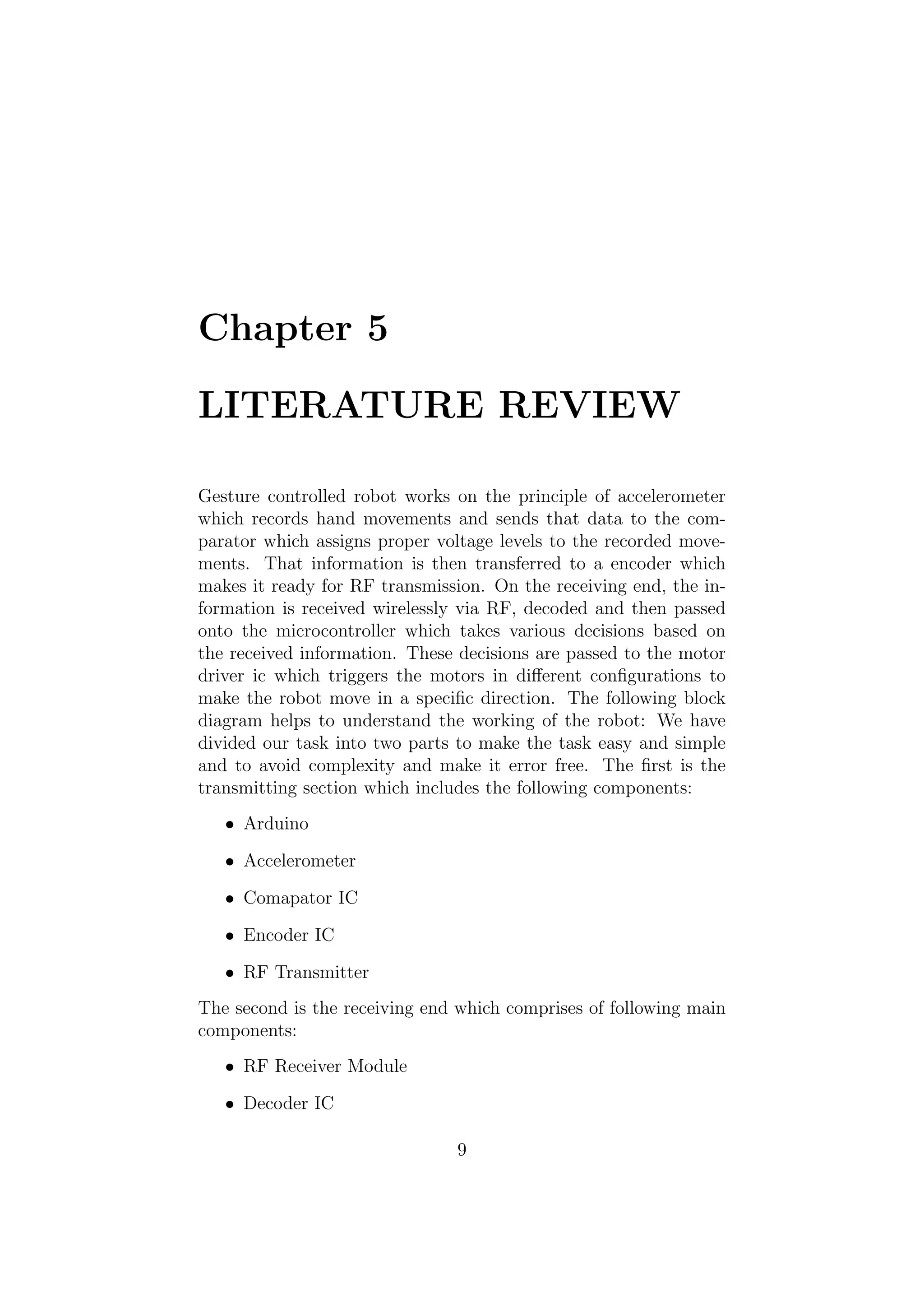
Gesturecontrolled robot works on the principle of accelerometer
which records hand movements and sends that data to the com-
parator which assigns proper voltage levels to the recorded move-
ments. That information is then transferred to a encoder which
makes it ready for RF transmission. On the receiving end, the in-
formation is received wirelessly via RF, decoded and then passed
onto the microcontroller which takes various decisions based on
the received information. These decisions are passed to the motor
driver ic which triggers the motors in different configurations to
make the robot move in a specific direction. The following block
diagram helps to understand the working of the robot: We have
divided our task into two parts to make the task easy and simple
and to avoid complexity and make it error free. The first is the
transmitting section which includes the following components:
• Arduino
• Accelerometer
• Comapator IC
• Encoder IC
• RF Transmitter
The second is the receiving end which comprises of following main
components:
• RF Receiver Module
• Decoder IC
9
11.
Figure 5.1: BlockDiagram of Robot
• Motor Driver IC
• DC Motors
• Wheels
5.1 Transmitter
5.1.1 Arduino
Arduino is an open source, computer hardware and software com-
pany, project, and user community that designs and manufactures
Single-board microcontrollers and microcontroller kits for building
digital devices and interactive objects that can sense and control
objects in the physical world. Arduino board designs use a variety
of microprocessors and controllers. The boards are equipped with
sets of digital and analog input/output (I/O) pins that may be
interfaced to various expansion boards (shields) and other circuits.
The boards feature serial communications interfaces, including Uni-
versal Serial Bus (USB) on some models, which are also used for
loading programs from personal computers. The microcontrollers
are typically programmed using a dialect of features from the pro-
gramming languages C and C++. In addition to using traditional
compiler toolchains, the Arduino project provides an integrated
development environment (IDE) based on the Processing language
project.Most Arduino boards consist of an Atmel 8-bit AVR mi-
crocontroller (ATmega8, ATmega168, ATmega328, ATmega1280,
10
12.
ATmega2560) with varyingamounts of flash memory, pins, and
features. The boards use single or double-row pins or female head-
ers that facilitate connections for programming and incorporation
into other circuits. These may connect with add-on modules termed
shields. Multiple, and possibly stacked shields may be individually
addressable via an IC serial bus. Most boards include a 5 V lin-
ear regulator and a 16 MHz crystal oscillator or ceramic resonator.
Some designs, such as the LilyPad, run at 8 MHz and dispense
with the onboard voltage regulator due to specific form-factor re-
strictions.
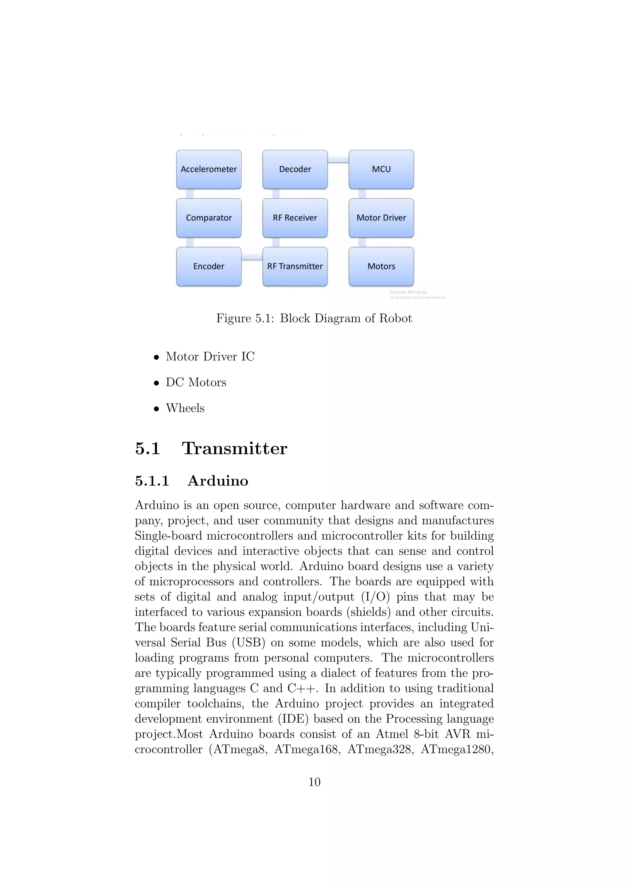
Here is the Pin Diagram of Arduino Atmega328:
Figure 5.2: Pin diagram of Atmega328
Pin Descriptions:
VCC : Digital supply voltage
GND : Ground
Port B (PB7) :Port B is an 8-bit bi-directional I/O port with in-
ternal pull-up resistors (selected for each bit). The Port B output
buffers have symmetrical drive characteristics with both high sink
and source capability. As inputs, Port B pins that are externally
pulled low will source current if the pull-up resistors are activated.
The Port B pins are tri-stated when a reset condition becomes
active, even if the clock is not running. Depending on the clock se-
lection fuse settings, PB7 can be used as output from the inverting
Oscillator amplifier.
11
13.
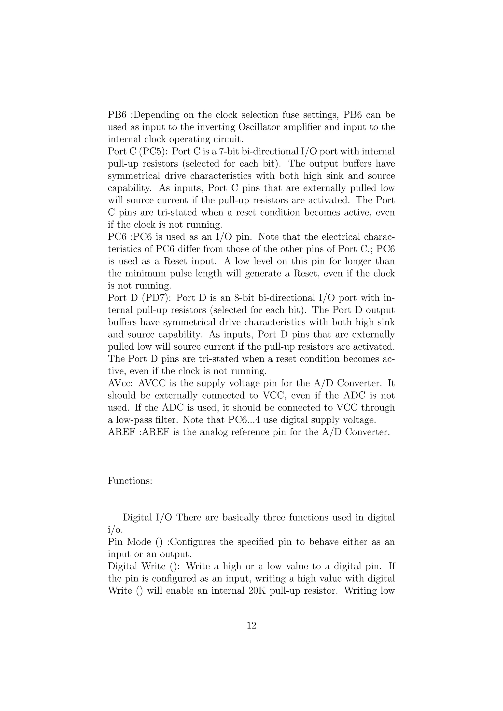
PB6 :Depending onthe clock selection fuse settings, PB6 can be
used as input to the inverting Oscillator amplifier and input to the
internal clock operating circuit.
Port C (PC5): Port C is a 7-bit bi-directional I/O port with internal
pull-up resistors (selected for each bit). The output buffers have
symmetrical drive characteristics with both high sink and source
capability. As inputs, Port C pins that are externally pulled low
will source current if the pull-up resistors are activated. The Port
C pins are tri-stated when a reset condition becomes active, even
if the clock is not running.
PC6 :PC6 is used as an I/O pin. Note that the electrical charac-
teristics of PC6 differ from those of the other pins of Port C.; PC6
is used as a Reset input. A low level on this pin for longer than
the minimum pulse length will generate a Reset, even if the clock
is not running.
Port D (PD7): Port D is an 8-bit bi-directional I/O port with in-
ternal pull-up resistors (selected for each bit). The Port D output
buffers have symmetrical drive characteristics with both high sink
and source capability. As inputs, Port D pins that are externally
pulled low will source current if the pull-up resistors are activated.
The Port D pins are tri-stated when a reset condition becomes ac-
tive, even if the clock is not running.
AVcc: AVCC is the supply voltage pin for the A/D Converter. It
should be externally connected to VCC, even if the ADC is not
used. If the ADC is used, it should be connected to VCC through
a low-pass filter. Note that PC6...4 use digital supply voltage.
AREF :AREF is the analog reference pin for the A/D Converter.
Functions:
Digital I/O There are basically three functions used in digital
i/o.
Pin Mode () :Configures the specified pin to behave either as an
input or an output.
Digital Write (): Write a high or a low value to a digital pin. If
the pin is configured as an input, writing a high value with digital
Write () will enable an internal 20K pull-up resistor. Writing low
12
14.
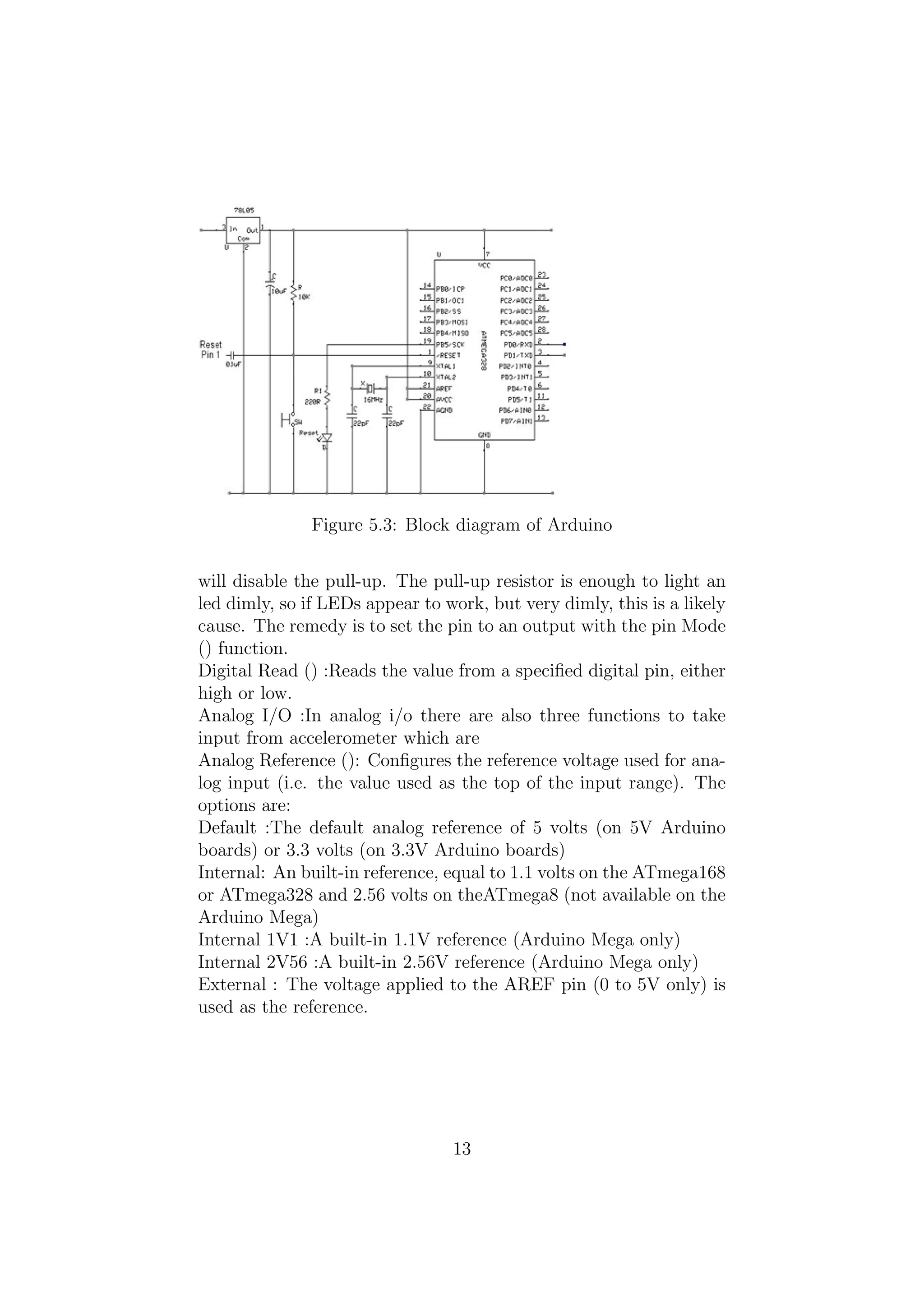
Figure 5.3: Blockdiagram of Arduino
will disable the pull-up. The pull-up resistor is enough to light an
led dimly, so if LEDs appear to work, but very dimly, this is a likely
cause. The remedy is to set the pin to an output with the pin Mode
() function.
Digital Read () :Reads the value from a specified digital pin, either
high or low.
Analog I/O :In analog i/o there are also three functions to take
input from accelerometer which are
Analog Reference (): Configures the reference voltage used for ana-
log input (i.e. the value used as the top of the input range). The
options are:
Default :The default analog reference of 5 volts (on 5V Arduino
boards) or 3.3 volts (on 3.3V Arduino boards)
Internal: An built-in reference, equal to 1.1 volts on the ATmega168
or ATmega328 and 2.56 volts on theATmega8 (not available on the
Arduino Mega)
Internal 1V1 :A built-in 1.1V reference (Arduino Mega only)
Internal 2V56 :A built-in 2.56V reference (Arduino Mega only)
External : The voltage applied to the AREF pin (0 to 5V only) is
used as the reference.
13
15.
5.1.2 Accelerometer (ADXL335)
Anaccelerometer is a device that measures proper acceleration,
also called the four-acceleration. However, the proper acceleration
measured by an accelerometer is not necessarily the coordinate ac-
celeration (rate of change of velocity). Instead, it is the accelera-
tion associated with the phenomenon of weight experienced by any
test mass at rest in the frame of reference of the accelerometer de-
vice. Single- and multi-axis models of accelerometer are available
to detect magnitude and direction of the proper acceleration as a
vector quantity, and can be used to sense orientation (because di-
rection of weight changes), coordinate vibration, shock, and falling
(a case where the proper acceleration changes, since it tends toward
zero). Pairs of accelerometers extended over a region of space can
be used to detect differences (gradients) in the proper accelerations
of frames associated with those points.
ADXL335 Accelerometer:
The ADXL335 is a small, thin, low power, complete 3-axis ac-
celerometer with signal conditioned voltage outputs. The product
measures acceleration with a minimum full-scale range of 3 g. It
can measure the static acceleration of gravity in tilt-sensing applica-
tions, as well as dynamic acceleration resulting from motion, shock,
or vibration. The user selects the bandwidth of the accelerometer
using the CX, CY, and CZ capacitors at the XOUT, YOUT, and
ZOUT pins. Bandwidths can be selected to suit the application,
with a range of 0.5 Hz to 1600 Hz for the X and Y axes, and a
range of 0.5 Hz to 550 Hz for the Z axis. It contains a poly silicon
surface-micro machined sensor and signal conditioning circuitry to
implement open-loop acceleration measurement architecture. The
output signals are analog voltages that are proportional to accel-
eration. The accelerometer can measure the static acceleration of
gravity in tilt-sensing applications as well as dynamic acceleration
resulting from motion, shock, or vibration. The sensor is a polysili-
con surface-micro machined structure built on top of a silicon wafer.
Polysilicon springs suspend the structure over the surface of the
wafer and provide a resistance against acceleration forces. Deflec-
tion of the structure is measured using a differential capacitor that
consists of independent fixed plates and plates attached to the mov-
ing mass. The fixed plates are driven by 180 out-of-phase square
14
16.
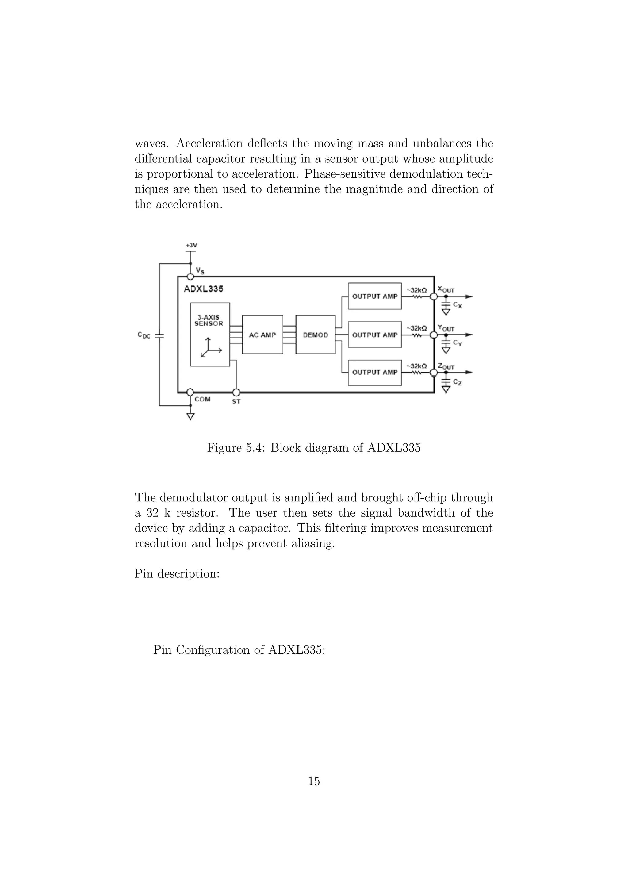
waves. Acceleration deflectsthe moving mass and unbalances the
differential capacitor resulting in a sensor output whose amplitude
is proportional to acceleration. Phase-sensitive demodulation tech-
niques are then used to determine the magnitude and direction of
the acceleration.
Figure 5.4: Block diagram of ADXL335
The demodulator output is amplified and brought off-chip through
a 32 k resistor. The user then sets the signal bandwidth of the
device by adding a capacitor. This filtering improves measurement
resolution and helps prevent aliasing.
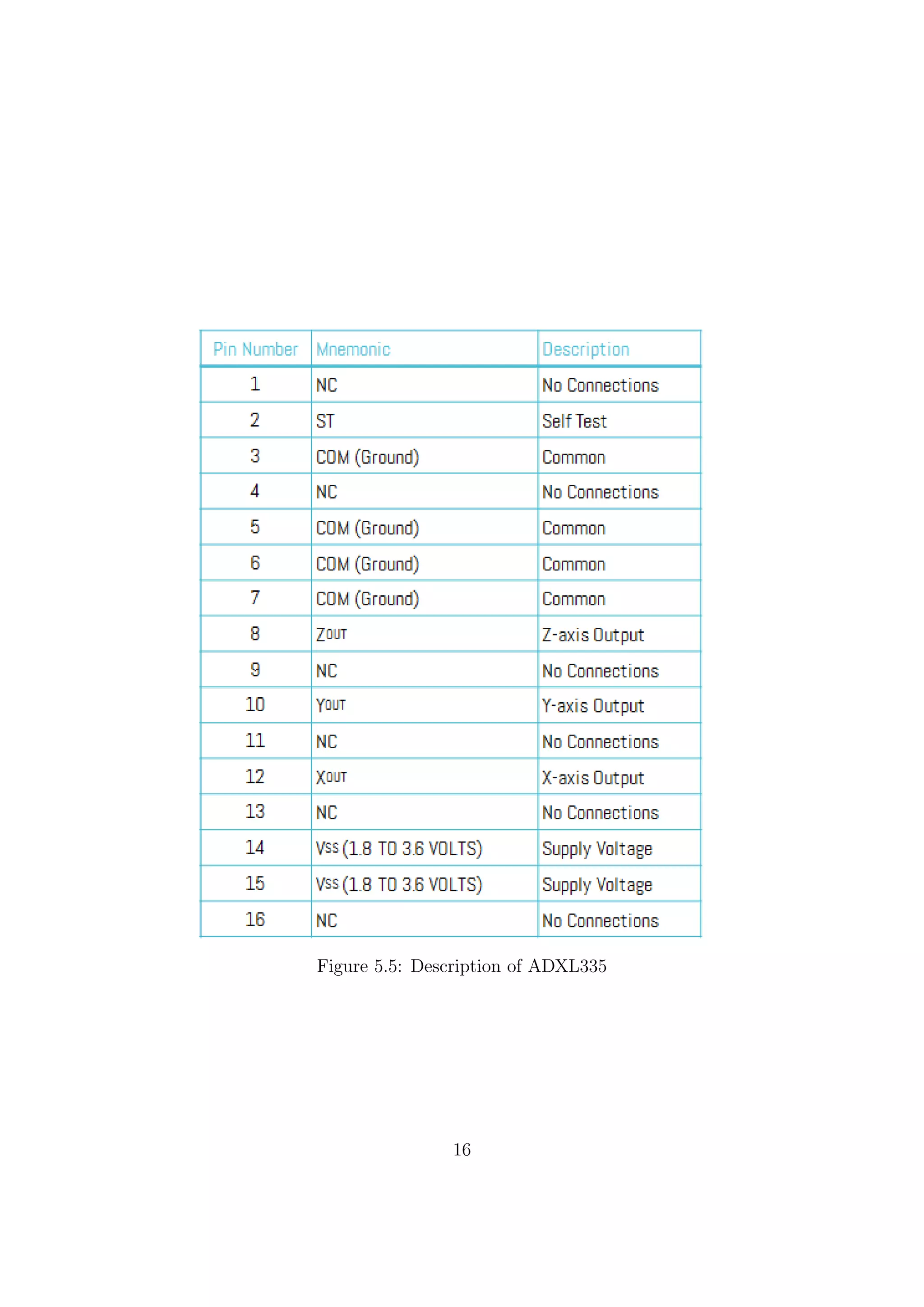
Pin description:
Pin Configuration of ADXL335:
15
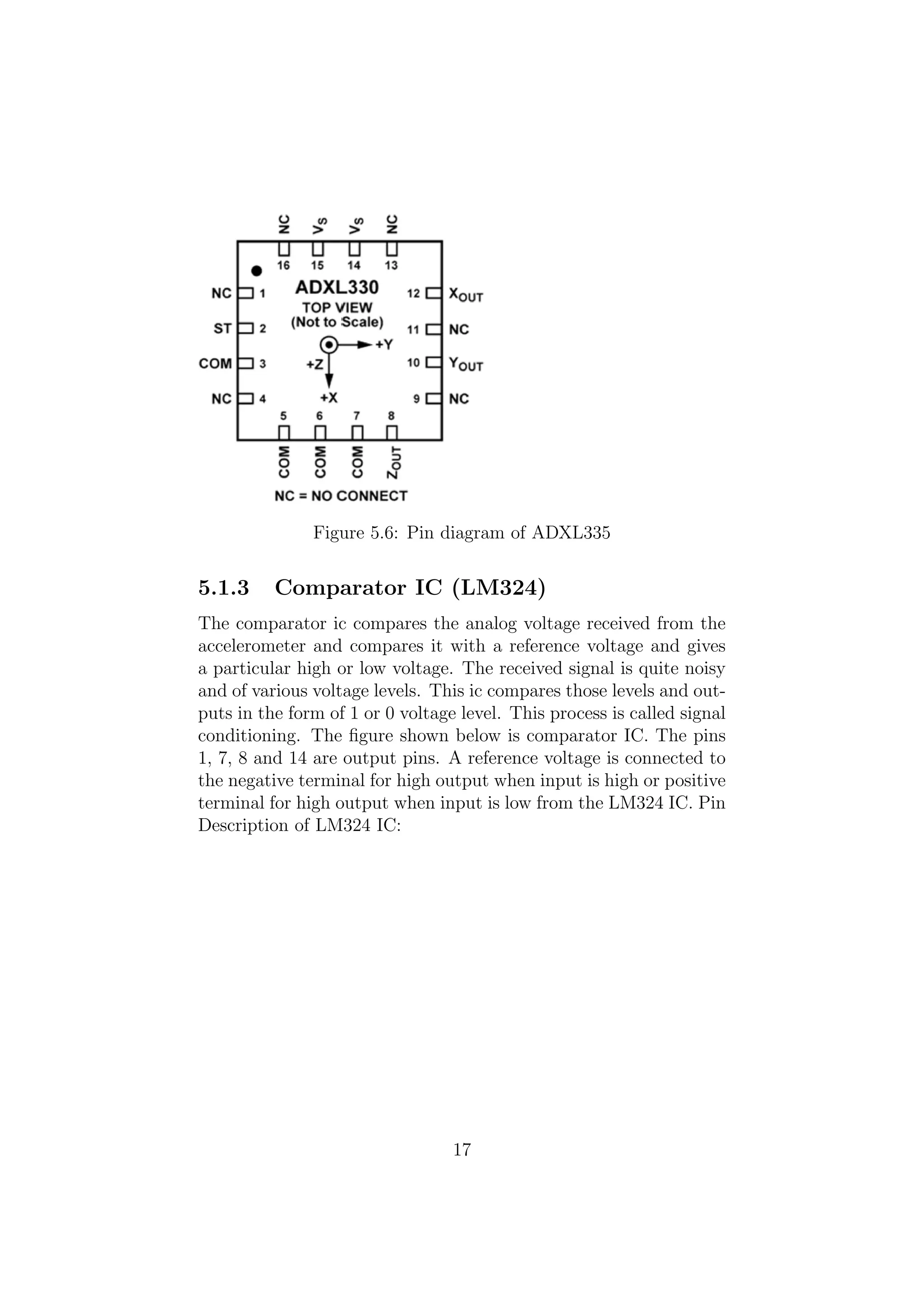
Figure 5.6: Pindiagram of ADXL335
5.1.3 Comparator IC (LM324)
The comparator ic compares the analog voltage received from the
accelerometer and compares it with a reference voltage and gives
a particular high or low voltage. The received signal is quite noisy
and of various voltage levels. This ic compares those levels and out-
puts in the form of 1 or 0 voltage level. This process is called signal
conditioning. The figure shown below is comparator IC. The pins
1, 7, 8 and 14 are output pins. A reference voltage is connected to
the negative terminal for high output when input is high or positive
terminal for high output when input is low from the LM324 IC. Pin
Description of LM324 IC:
17
19.
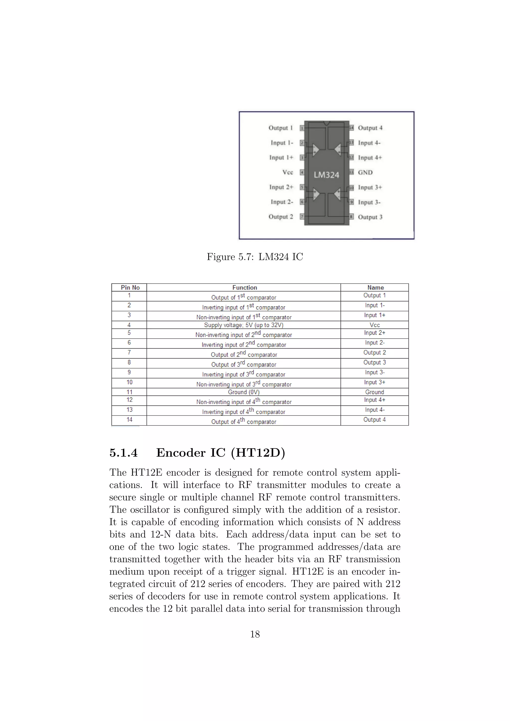
Figure 5.7: LM324IC
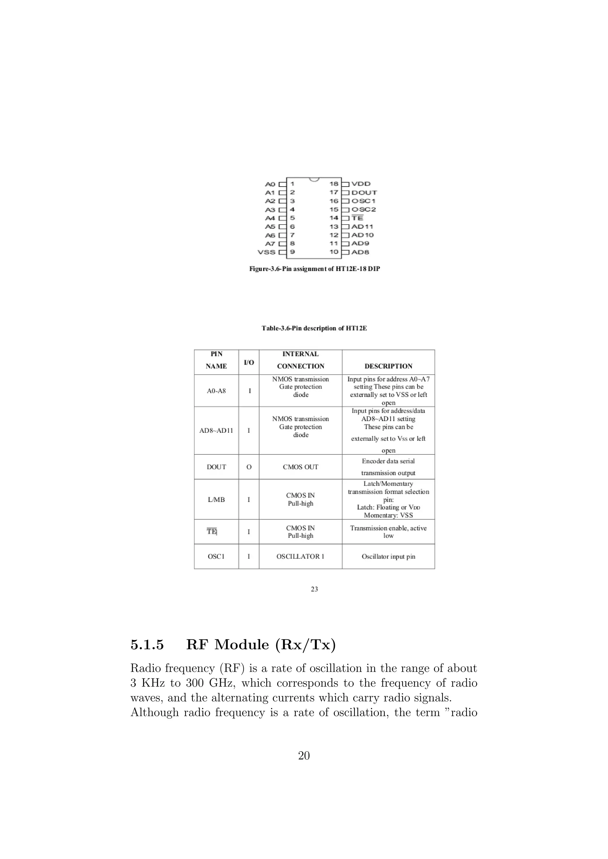
5.1.4 Encoder IC (HT12D)
The HT12E encoder is designed for remote control system appli-
cations. It will interface to RF transmitter modules to create a
secure single or multiple channel RF remote control transmitters.
The oscillator is configured simply with the addition of a resistor.
It is capable of encoding information which consists of N address
bits and 12-N data bits. Each address/data input can be set to
one of the two logic states. The programmed addresses/data are
transmitted together with the header bits via an RF transmission
medium upon receipt of a trigger signal. HT12E is an encoder in-
tegrated circuit of 212 series of encoders. They are paired with 212
series of decoders for use in remote control system applications. It
encodes the 12 bit parallel data into serial for transmission through
18
20.
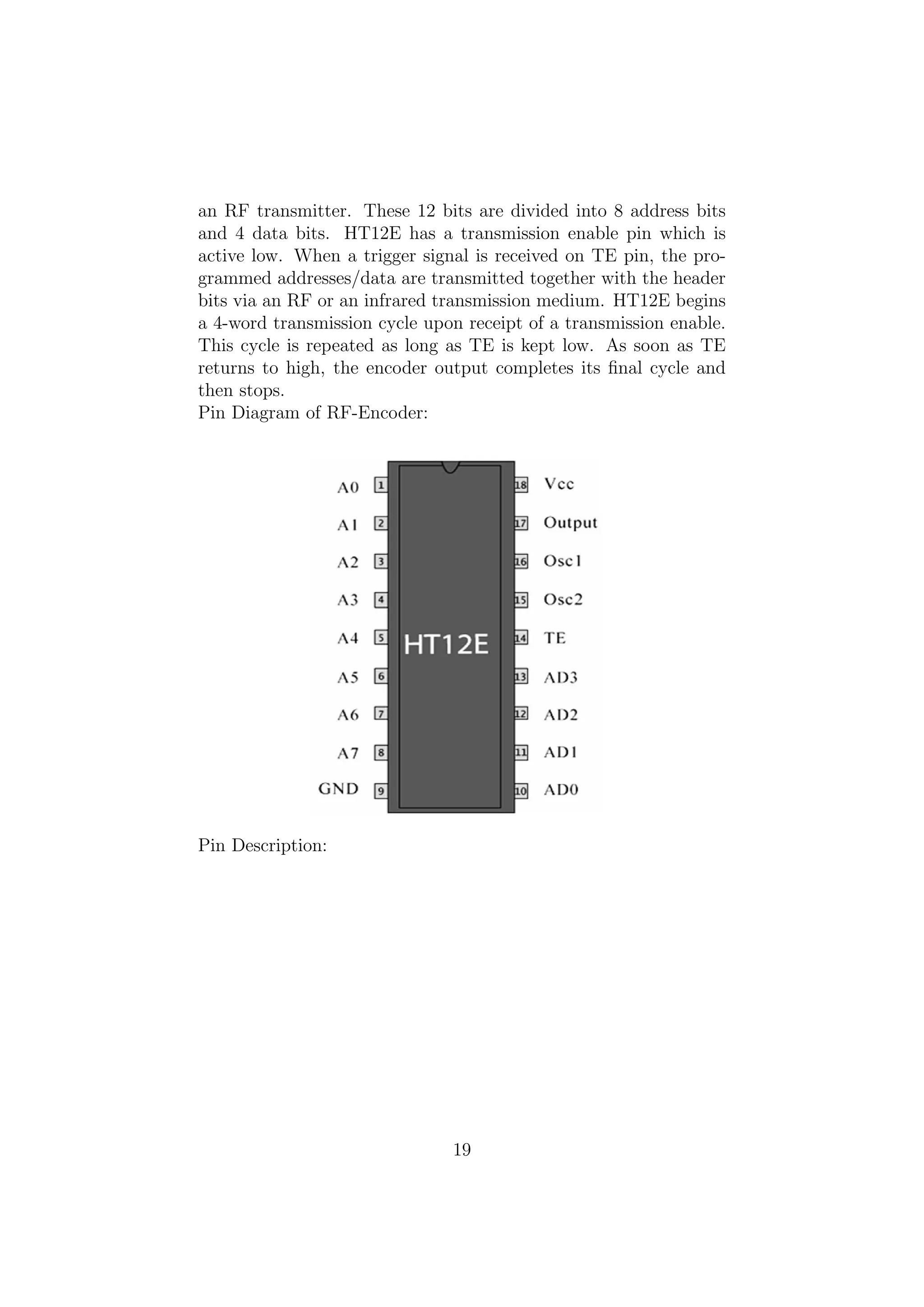
an RF transmitter.These 12 bits are divided into 8 address bits
and 4 data bits. HT12E has a transmission enable pin which is
active low. When a trigger signal is received on TE pin, the pro-
grammed addresses/data are transmitted together with the header
bits via an RF or an infrared transmission medium. HT12E begins
a 4-word transmission cycle upon receipt of a transmission enable.
This cycle is repeated as long as TE is kept low. As soon as TE
returns to high, the encoder output completes its final cycle and
then stops.
Pin Diagram of RF-Encoder:
Pin Description:
19
21.
5.1.5 RF Module(Rx/Tx)
Radio frequency (RF) is a rate of oscillation in the range of about
3 KHz to 300 GHz, which corresponds to the frequency of radio
waves, and the alternating currents which carry radio signals.
Although radio frequency is a rate of oscillation, the term ”radio
20
22.
frequency” or itsabbreviation ”RF” are also used as a synonym
for radio i.e. to describe the use of wireless communication, as
opposed to communication via electric wires/
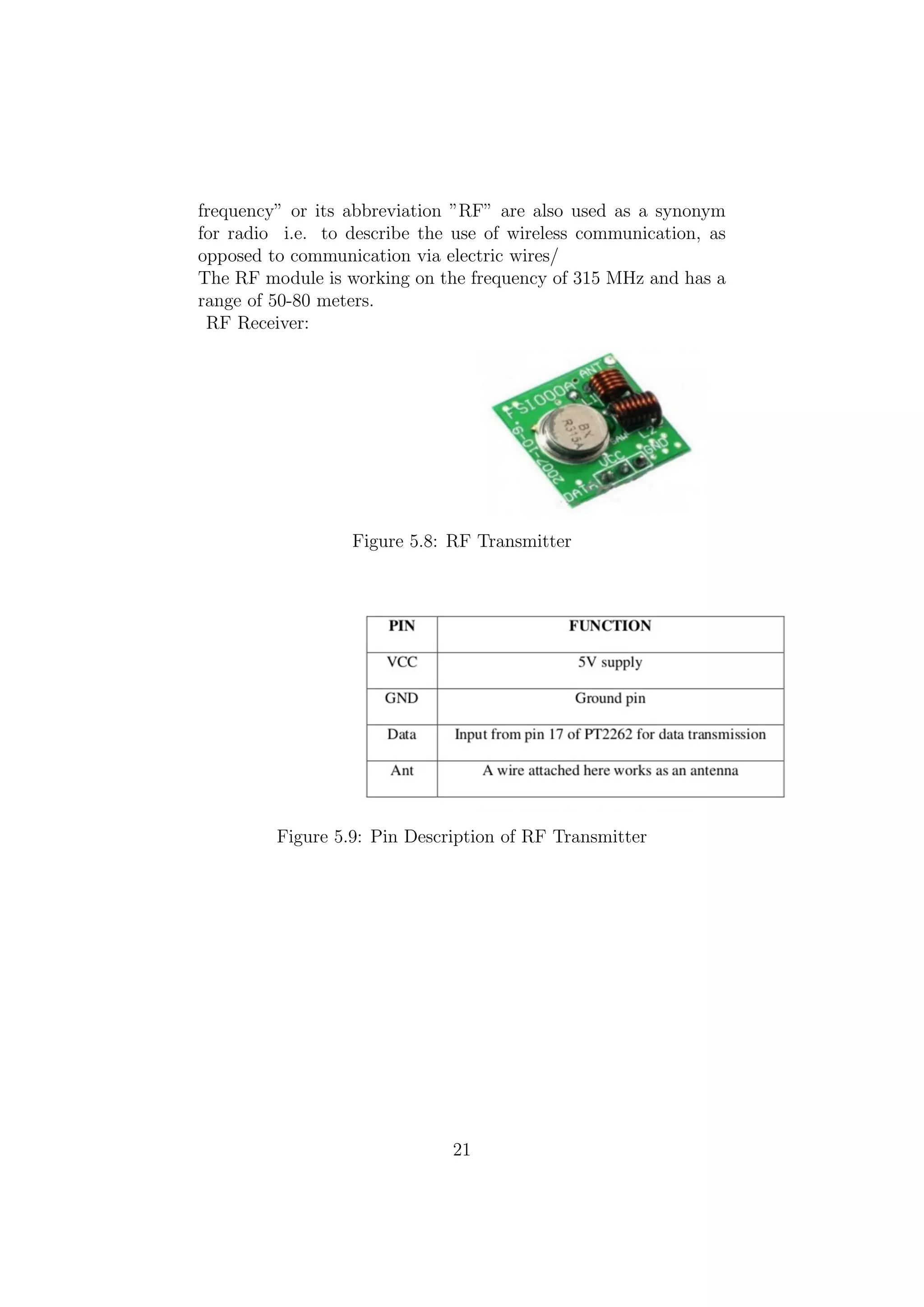
The RF module is working on the frequency of 315 MHz and has a
range of 50-80 meters.
RF Receiver:
Figure 5.8: RF Transmitter
Figure 5.9: Pin Description of RF Transmitter
21
23.
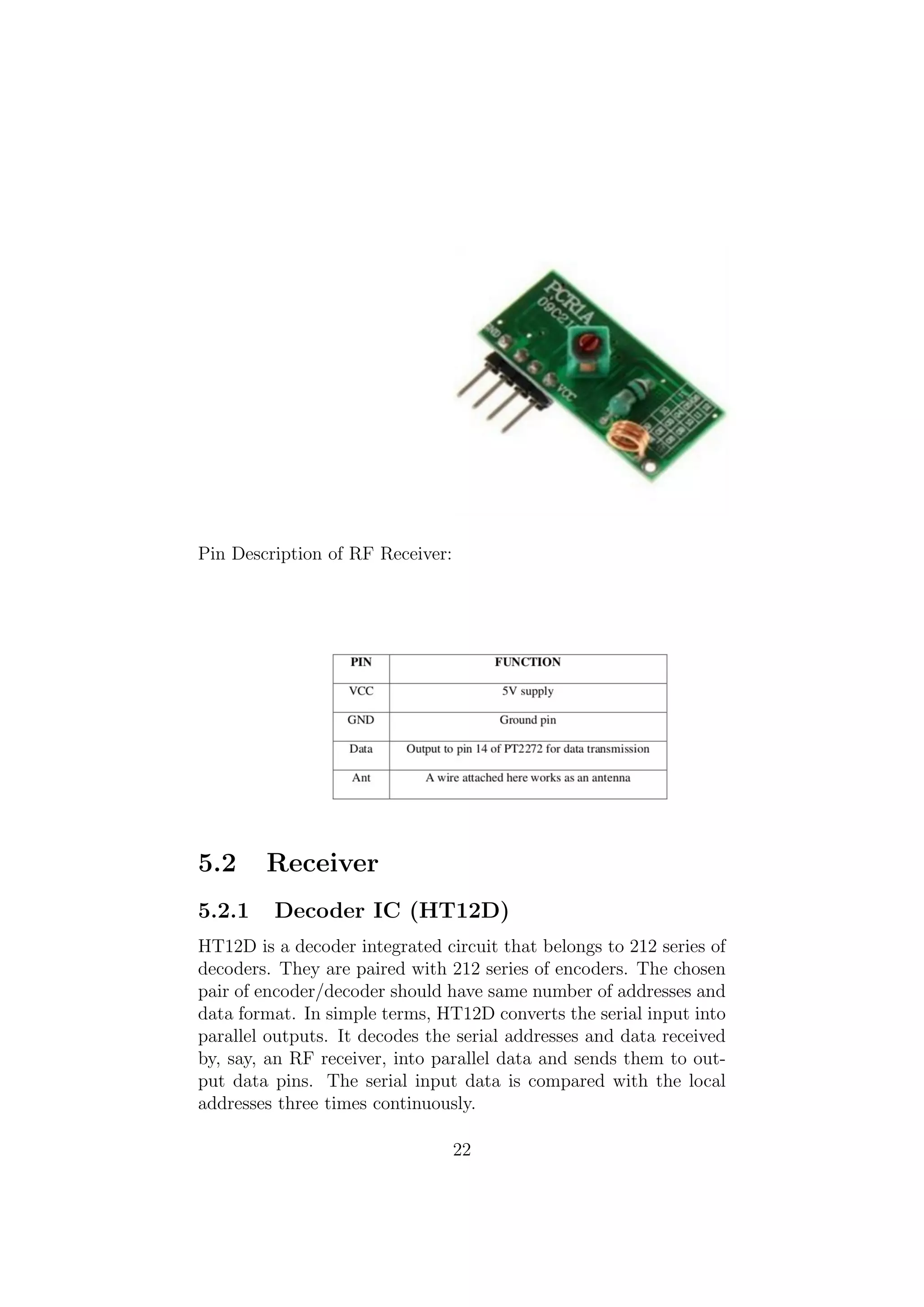
Pin Description ofRF Receiver:
5.2 Receiver
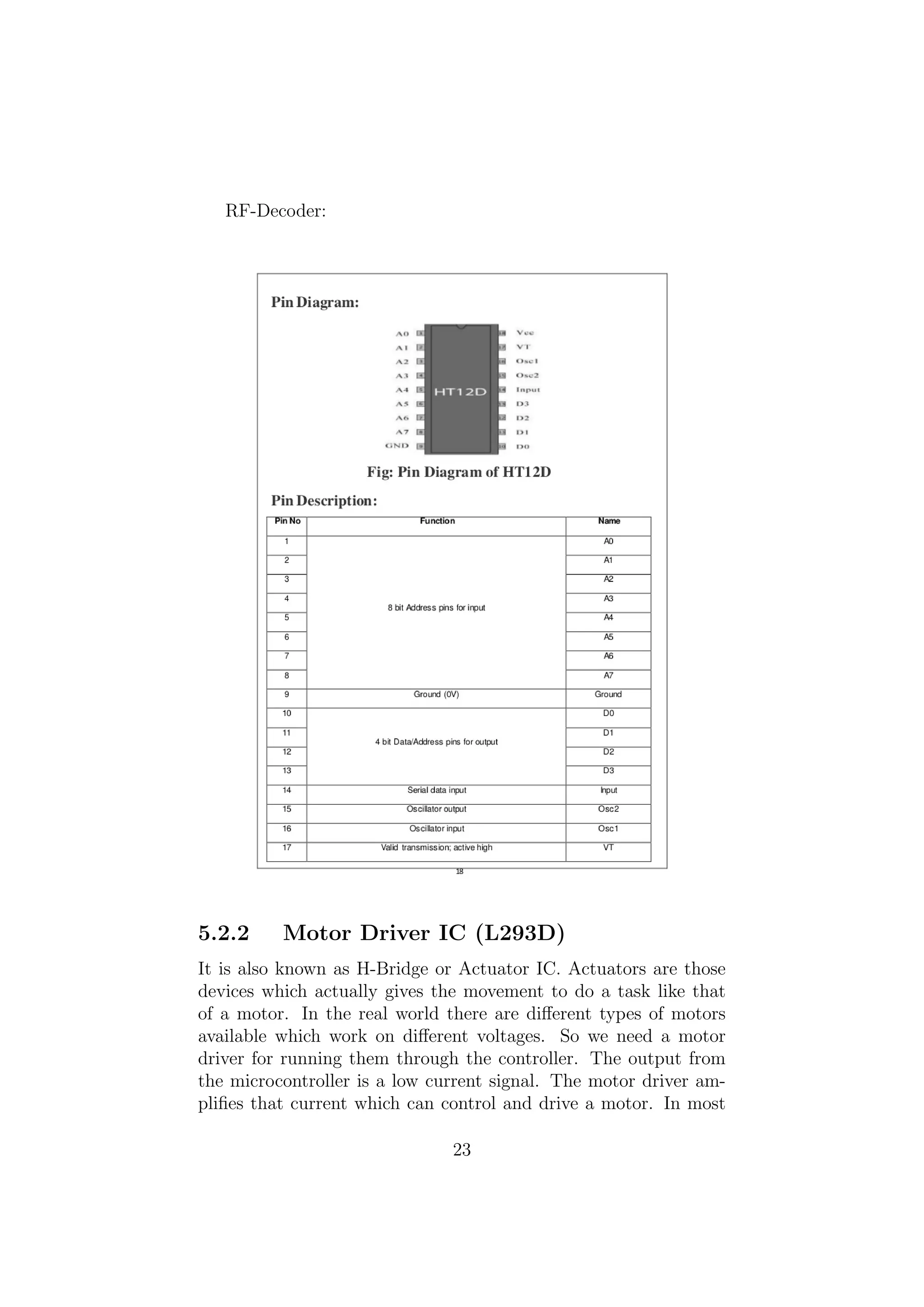
5.2.1 Decoder IC (HT12D)
HT12D is a decoder integrated circuit that belongs to 212 series of
decoders. They are paired with 212 series of encoders. The chosen
pair of encoder/decoder should have same number of addresses and
data format. In simple terms, HT12D converts the serial input into
parallel outputs. It decodes the serial addresses and data received
by, say, an RF receiver, into parallel data and sends them to out-
put data pins. The serial input data is compared with the local
addresses three times continuously.
22
24.
RF-Decoder:
5.2.2 Motor DriverIC (L293D)
It is also known as H-Bridge or Actuator IC. Actuators are those
devices which actually gives the movement to do a task like that
of a motor. In the real world there are different types of motors
available which work on different voltages. So we need a motor
driver for running them through the controller. The output from
the microcontroller is a low current signal. The motor driver am-
plifies that current which can control and drive a motor. In most
23
25.
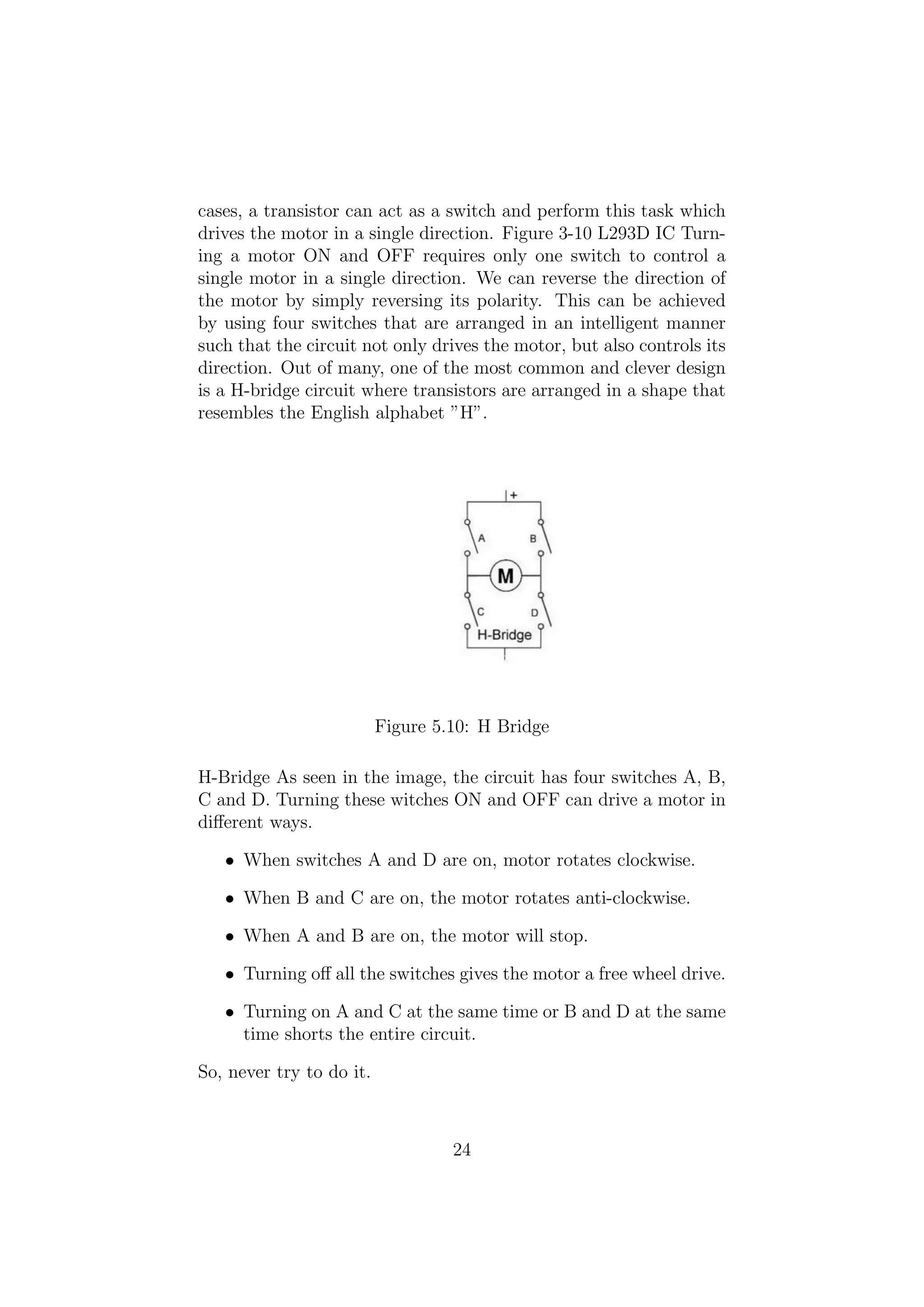
cases, a transistorcan act as a switch and perform this task which
drives the motor in a single direction. Figure 3-10 L293D IC Turn-
ing a motor ON and OFF requires only one switch to control a
single motor in a single direction. We can reverse the direction of
the motor by simply reversing its polarity. This can be achieved
by using four switches that are arranged in an intelligent manner
such that the circuit not only drives the motor, but also controls its
direction. Out of many, one of the most common and clever design
is a H-bridge circuit where transistors are arranged in a shape that
resembles the English alphabet ”H”.
Figure 5.10: H Bridge
H-Bridge As seen in the image, the circuit has four switches A, B,
C and D. Turning these witches ON and OFF can drive a motor in
different ways.
• When switches A and D are on, motor rotates clockwise.
• When B and C are on, the motor rotates anti-clockwise.
• When A and B are on, the motor will stop.
• Turning off all the switches gives the motor a free wheel drive.
• Turning on A and C at the same time or B and D at the same
time shorts the entire circuit.
So, never try to do it.
24
26.
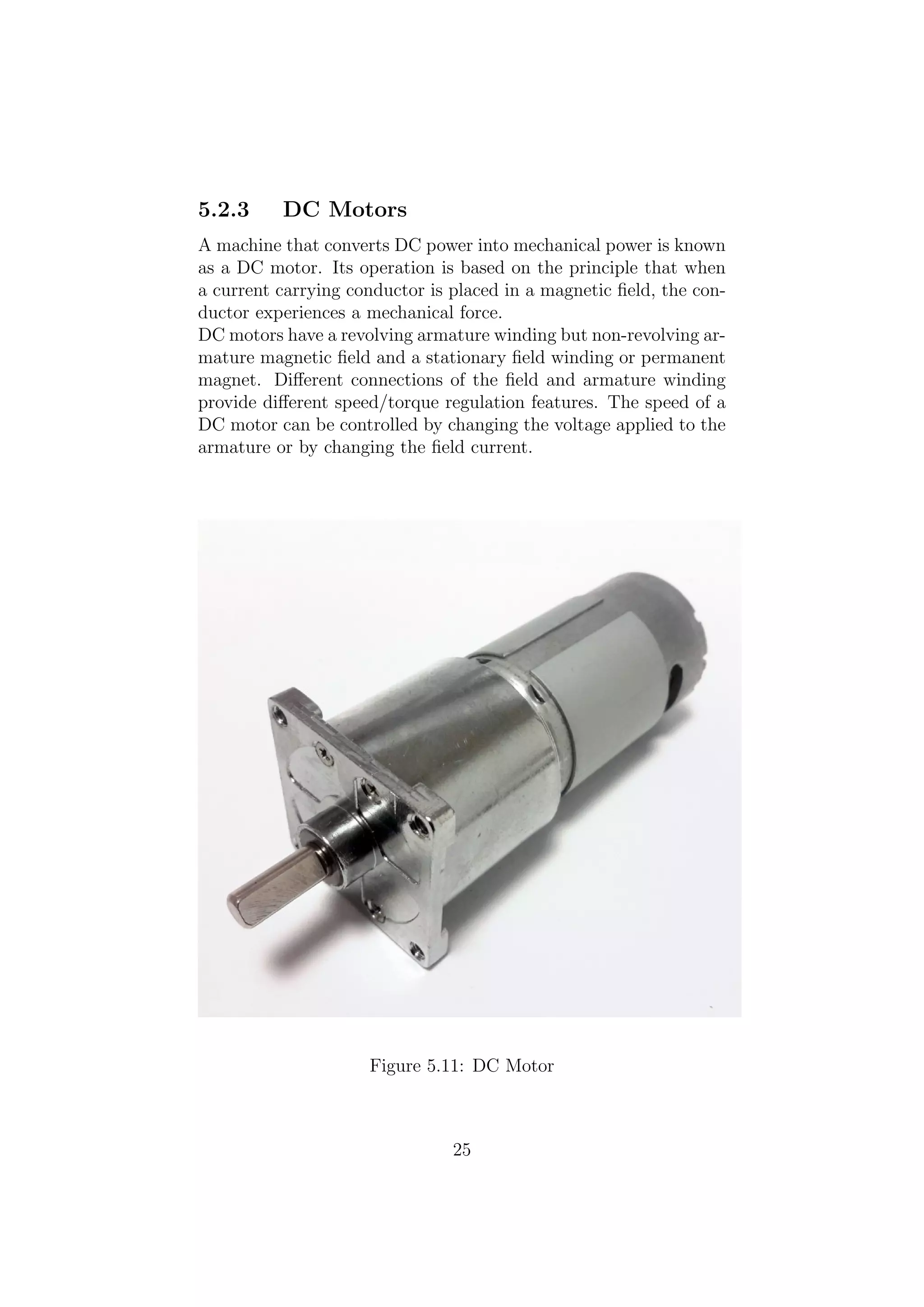
5.2.3 DC Motors
Amachine that converts DC power into mechanical power is known
as a DC motor. Its operation is based on the principle that when
a current carrying conductor is placed in a magnetic field, the con-
ductor experiences a mechanical force.
DC motors have a revolving armature winding but non-revolving ar-
mature magnetic field and a stationary field winding or permanent
magnet. Different connections of the field and armature winding
provide different speed/torque regulation features. The speed of a
DC motor can be controlled by changing the voltage applied to the
armature or by changing the field current.
Figure 5.11: DC Motor
25
27.
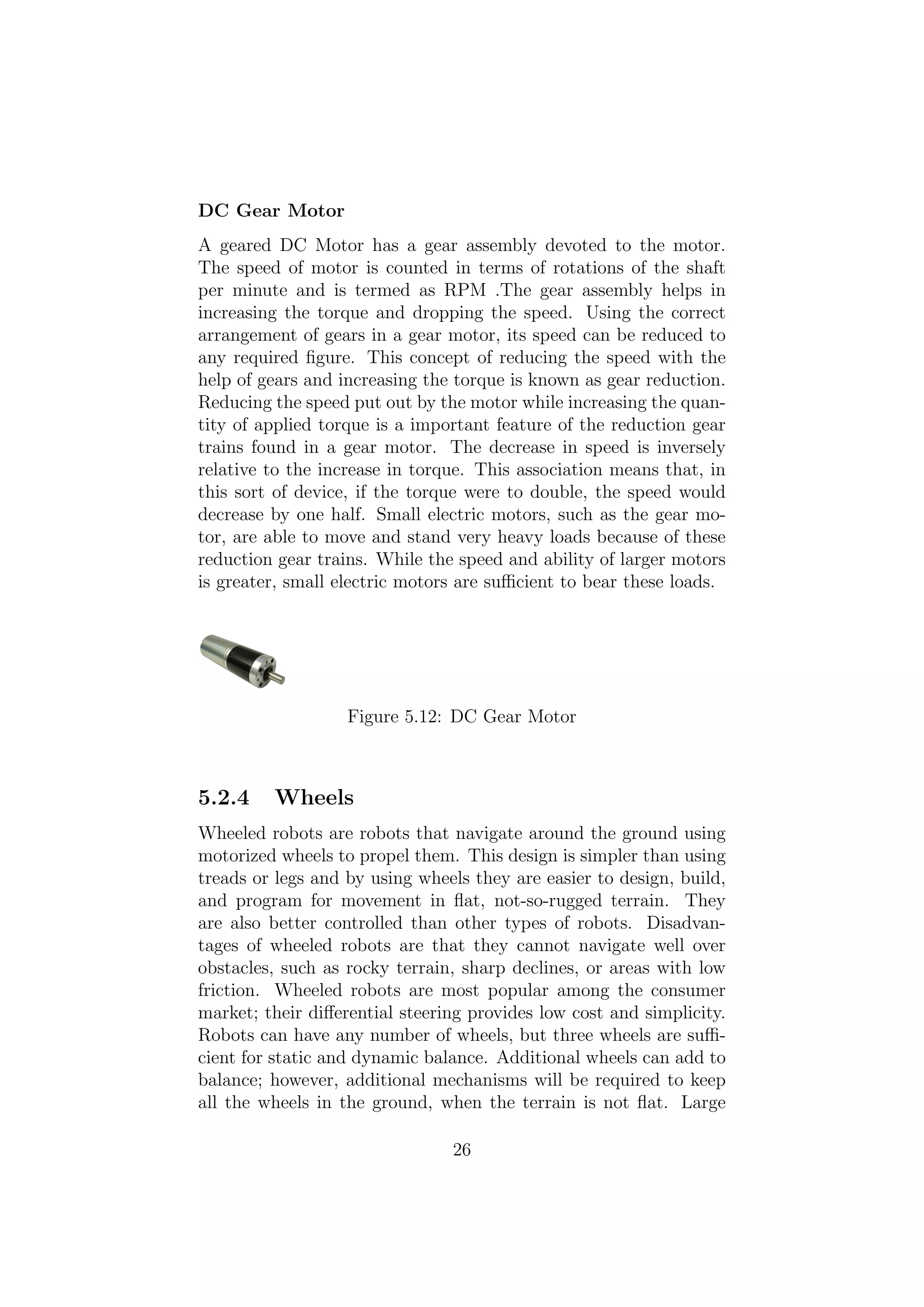
DC Gear Motor
Ageared DC Motor has a gear assembly devoted to the motor.
The speed of motor is counted in terms of rotations of the shaft
per minute and is termed as RPM .The gear assembly helps in
increasing the torque and dropping the speed. Using the correct
arrangement of gears in a gear motor, its speed can be reduced to
any required figure. This concept of reducing the speed with the
help of gears and increasing the torque is known as gear reduction.
Reducing the speed put out by the motor while increasing the quan-
tity of applied torque is a important feature of the reduction gear
trains found in a gear motor. The decrease in speed is inversely
relative to the increase in torque. This association means that, in
this sort of device, if the torque were to double, the speed would
decrease by one half. Small electric motors, such as the gear mo-
tor, are able to move and stand very heavy loads because of these
reduction gear trains. While the speed and ability of larger motors
is greater, small electric motors are sufficient to bear these loads.
Figure 5.12: DC Gear Motor
5.2.4 Wheels
Wheeled robots are robots that navigate around the ground using
motorized wheels to propel them. This design is simpler than using
treads or legs and by using wheels they are easier to design, build,
and program for movement in flat, not-so-rugged terrain. They
are also better controlled than other types of robots. Disadvan-
tages of wheeled robots are that they cannot navigate well over
obstacles, such as rocky terrain, sharp declines, or areas with low
friction. Wheeled robots are most popular among the consumer
market; their differential steering provides low cost and simplicity.
Robots can have any number of wheels, but three wheels are suffi-
cient for static and dynamic balance. Additional wheels can add to
balance; however, additional mechanisms will be required to keep
all the wheels in the ground, when the terrain is not flat. Large
26
28.
diameter wheels givethe robot low torque but high velocity.
Types of wheels:
• 2 wheeled robot
• 3 wheeled robot
• 4 wheeled robot
• 5 or more wheeled robot
Here in the project,we use 3-Wheeled robot.
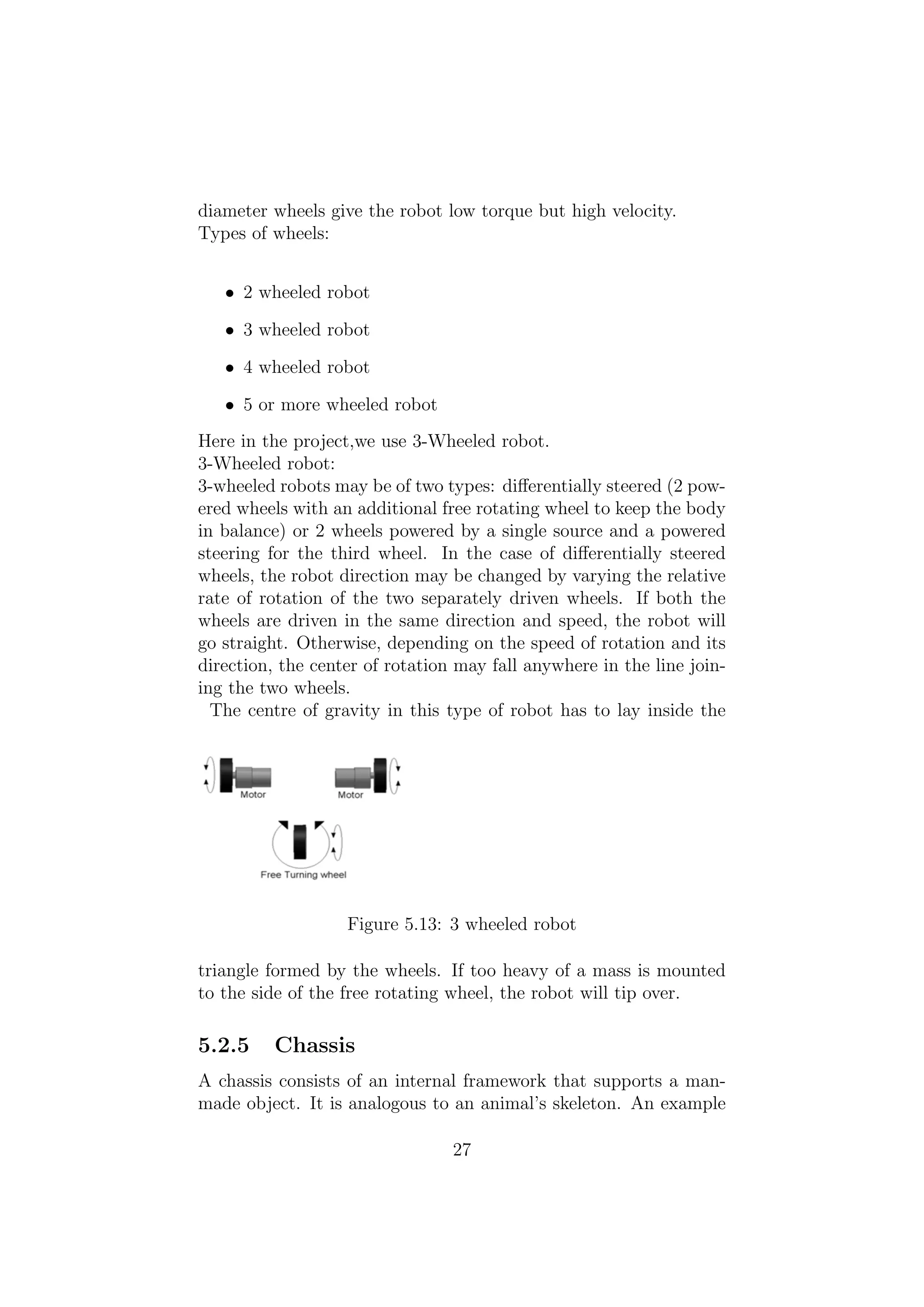
3-Wheeled robot:
3-wheeled robots may be of two types: differentially steered (2 pow-
ered wheels with an additional free rotating wheel to keep the body
in balance) or 2 wheels powered by a single source and a powered
steering for the third wheel. In the case of differentially steered
wheels, the robot direction may be changed by varying the relative
rate of rotation of the two separately driven wheels. If both the
wheels are driven in the same direction and speed, the robot will
go straight. Otherwise, depending on the speed of rotation and its
direction, the center of rotation may fall anywhere in the line join-
ing the two wheels.
The centre of gravity in this type of robot has to lay inside the
Figure 5.13: 3 wheeled robot
triangle formed by the wheels. If too heavy of a mass is mounted
to the side of the free rotating wheel, the robot will tip over.
5.2.5 Chassis
A chassis consists of an internal framework that supports a man-
made object. It is analogous to an animal’s skeleton. An example
27
29.
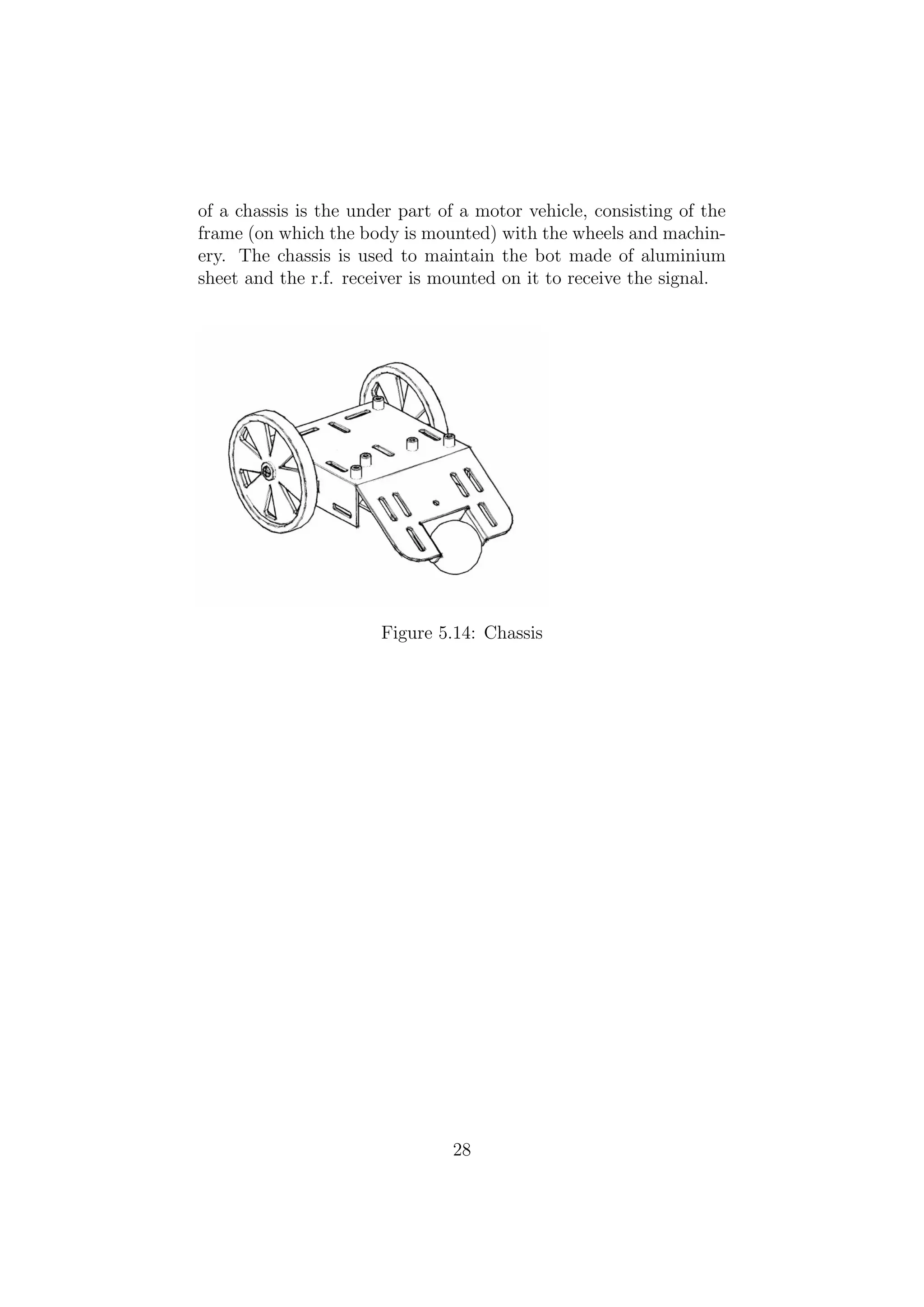
of a chassisis the under part of a motor vehicle, consisting of the
frame (on which the body is mounted) with the wheels and machin-
ery. The chassis is used to maintain the bot made of aluminium
sheet and the r.f. receiver is mounted on it to receive the signal.
Figure 5.14: Chassis
28
30.
Chapter 6
IMPLEMENTATION
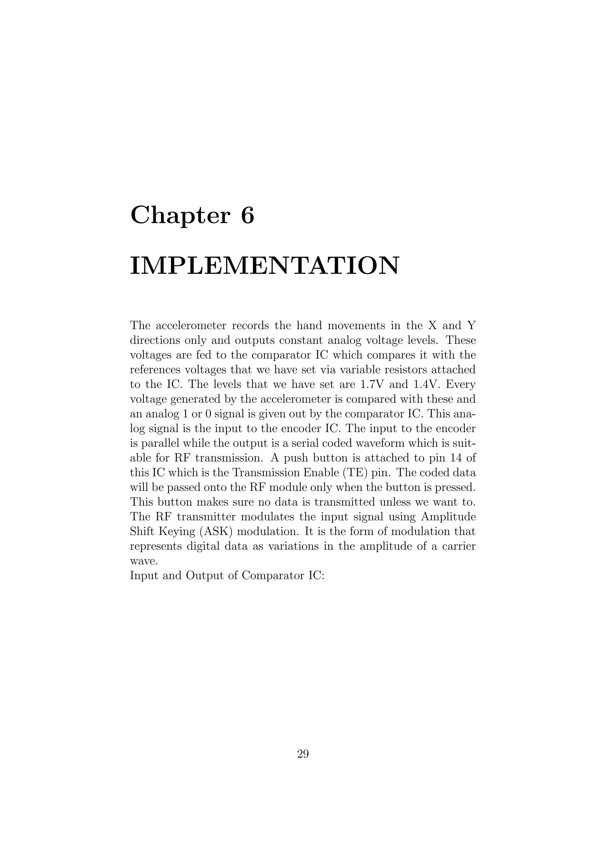
The accelerometerrecords the hand movements in the X and Y
directions only and outputs constant analog voltage levels. These
voltages are fed to the comparator IC which compares it with the
references voltages that we have set via variable resistors attached
to the IC. The levels that we have set are 1.7V and 1.4V. Every
voltage generated by the accelerometer is compared with these and
an analog 1 or 0 signal is given out by the comparator IC. This ana-
log signal is the input to the encoder IC. The input to the encoder
is parallel while the output is a serial coded waveform which is suit-
able for RF transmission. A push button is attached to pin 14 of
this IC which is the Transmission Enable (TE) pin. The coded data
will be passed onto the RF module only when the button is pressed.
This button makes sure no data is transmitted unless we want to.
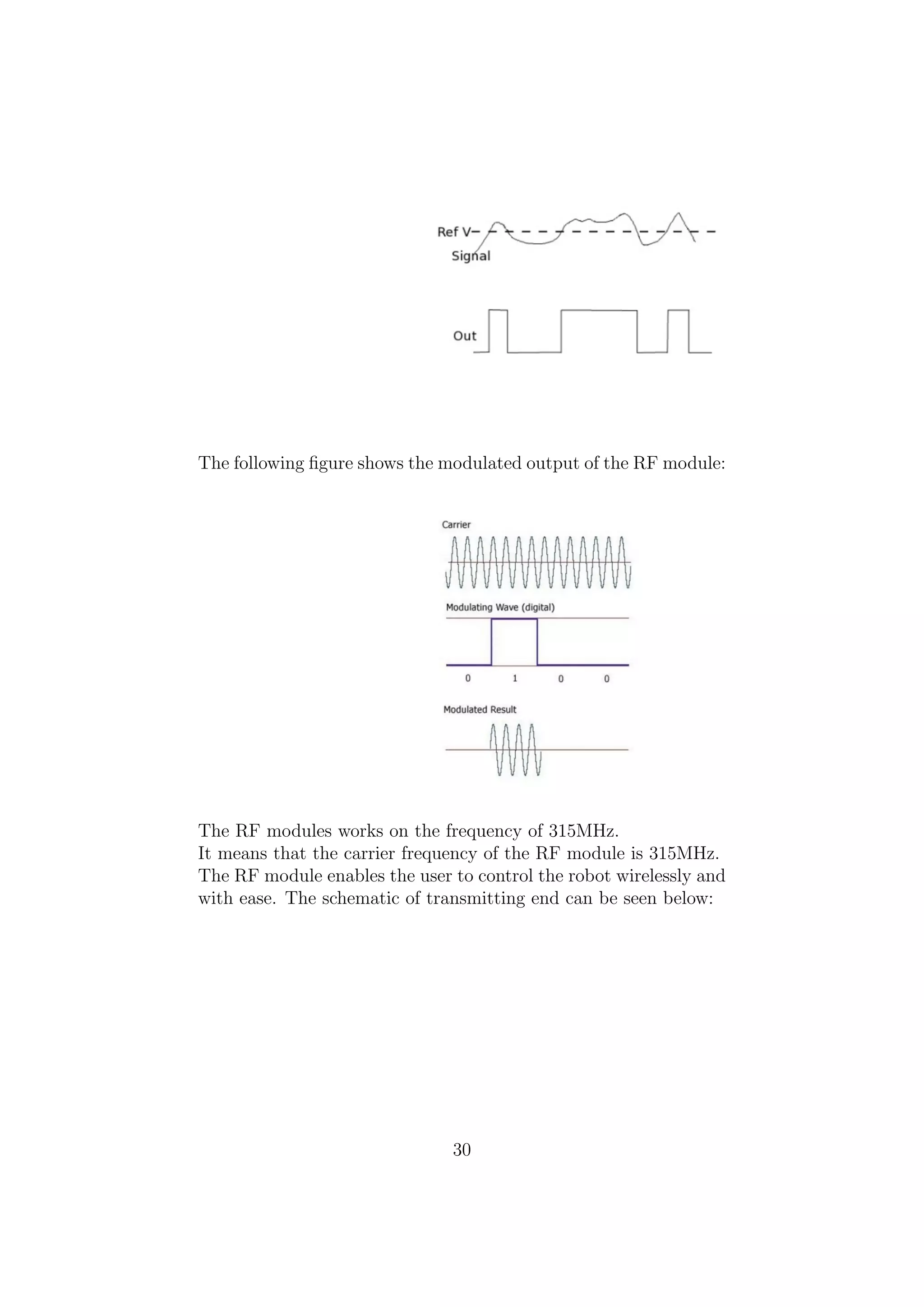
The RF transmitter modulates the input signal using Amplitude
Shift Keying (ASK) modulation. It is the form of modulation that
represents digital data as variations in the amplitude of a carrier
wave.
Input and Output of Comparator IC:
29
31.
The following figureshows the modulated output of the RF module:
The RF modules works on the frequency of 315MHz.
It means that the carrier frequency of the RF module is 315MHz.
The RF module enables the user to control the robot wirelessly and
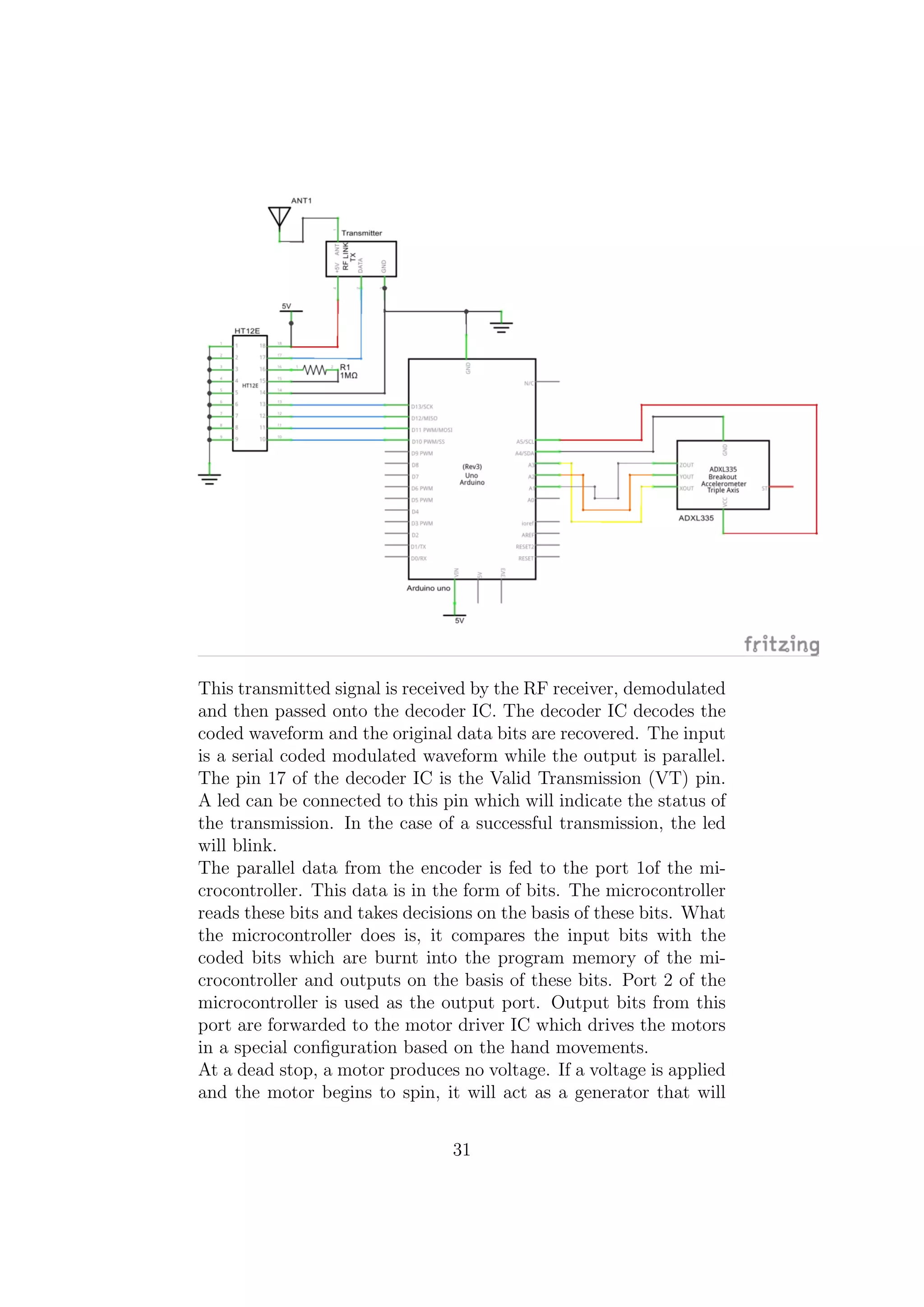
with ease. The schematic of transmitting end can be seen below:
30
32.
This transmitted signalis received by the RF receiver, demodulated
and then passed onto the decoder IC. The decoder IC decodes the
coded waveform and the original data bits are recovered. The input
is a serial coded modulated waveform while the output is parallel.
The pin 17 of the decoder IC is the Valid Transmission (VT) pin.
A led can be connected to this pin which will indicate the status of
the transmission. In the case of a successful transmission, the led
will blink.
The parallel data from the encoder is fed to the port 1of the mi-
crocontroller. This data is in the form of bits. The microcontroller
reads these bits and takes decisions on the basis of these bits. What
the microcontroller does is, it compares the input bits with the
coded bits which are burnt into the program memory of the mi-
crocontroller and outputs on the basis of these bits. Port 2 of the
microcontroller is used as the output port. Output bits from this
port are forwarded to the motor driver IC which drives the motors
in a special configuration based on the hand movements.
At a dead stop, a motor produces no voltage. If a voltage is applied
and the motor begins to spin, it will act as a generator that will
31
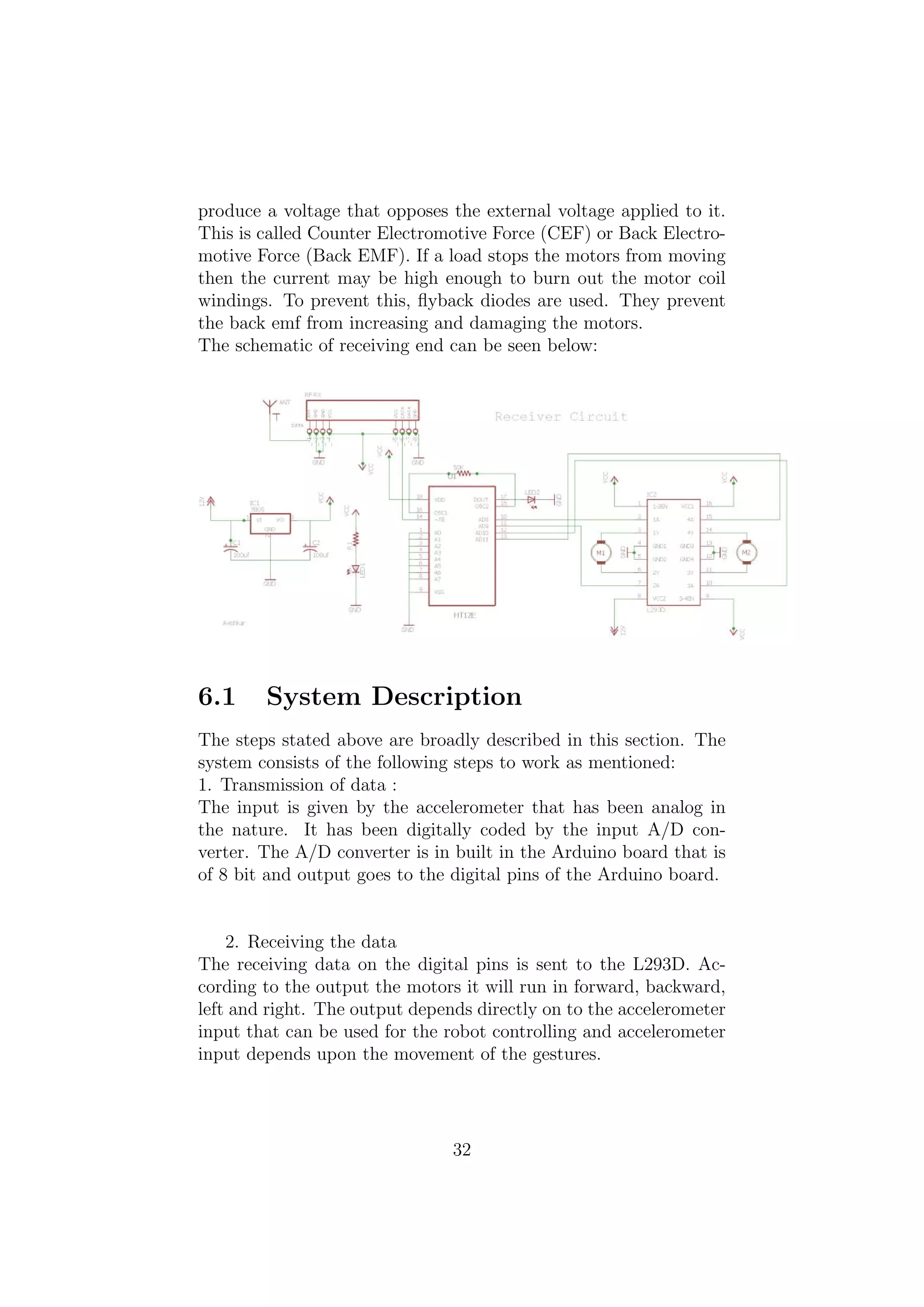
33.
produce a voltagethat opposes the external voltage applied to it.
This is called Counter Electromotive Force (CEF) or Back Electro-
motive Force (Back EMF). If a load stops the motors from moving
then the current may be high enough to burn out the motor coil
windings. To prevent this, flyback diodes are used. They prevent
the back emf from increasing and damaging the motors.
The schematic of receiving end can be seen below:
6.1 System Description
The steps stated above are broadly described in this section. The
system consists of the following steps to work as mentioned:
1. Transmission of data :
The input is given by the accelerometer that has been analog in
the nature. It has been digitally coded by the input A/D con-
verter. The A/D converter is in built in the Arduino board that is
of 8 bit and output goes to the digital pins of the Arduino board.
2. Receiving the data
The receiving data on the digital pins is sent to the L293D. Ac-
cording to the output the motors it will run in forward, backward,
left and right. The output depends directly on to the accelerometer
input that can be used for the robot controlling and accelerometer
input depends upon the movement of the gestures.
32
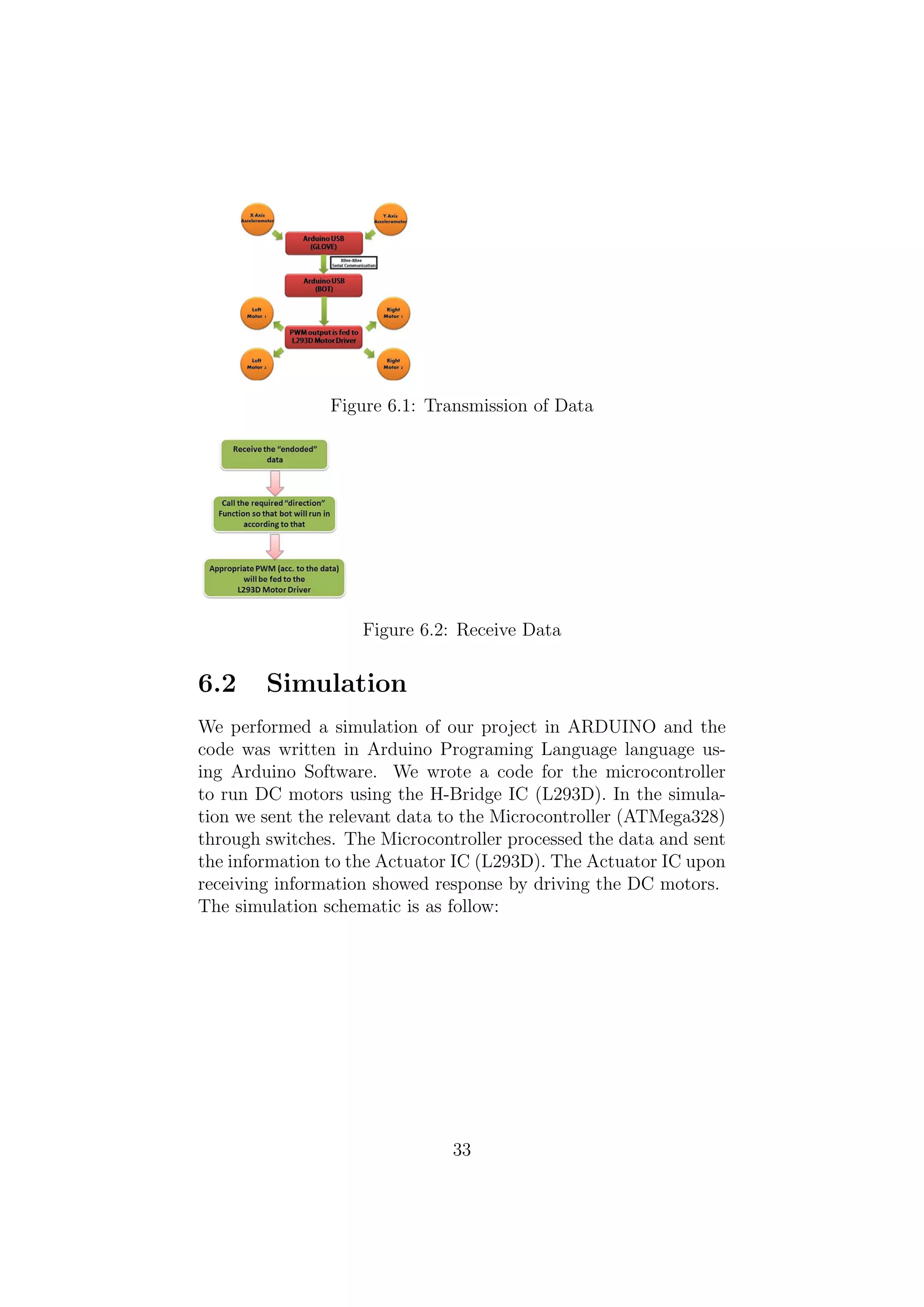
34.
Figure 6.1: Transmissionof Data
Figure 6.2: Receive Data
6.2 Simulation
We performed a simulation of our project in ARDUINO and the
code was written in Arduino Programing Language language us-
ing Arduino Software. We wrote a code for the microcontroller
to run DC motors using the H-Bridge IC (L293D). In the simula-
tion we sent the relevant data to the Microcontroller (ATMega328)
through switches. The Microcontroller processed the data and sent
the information to the Actuator IC (L293D). The Actuator IC upon
receiving information showed response by driving the DC motors.
The simulation schematic is as follow:
33
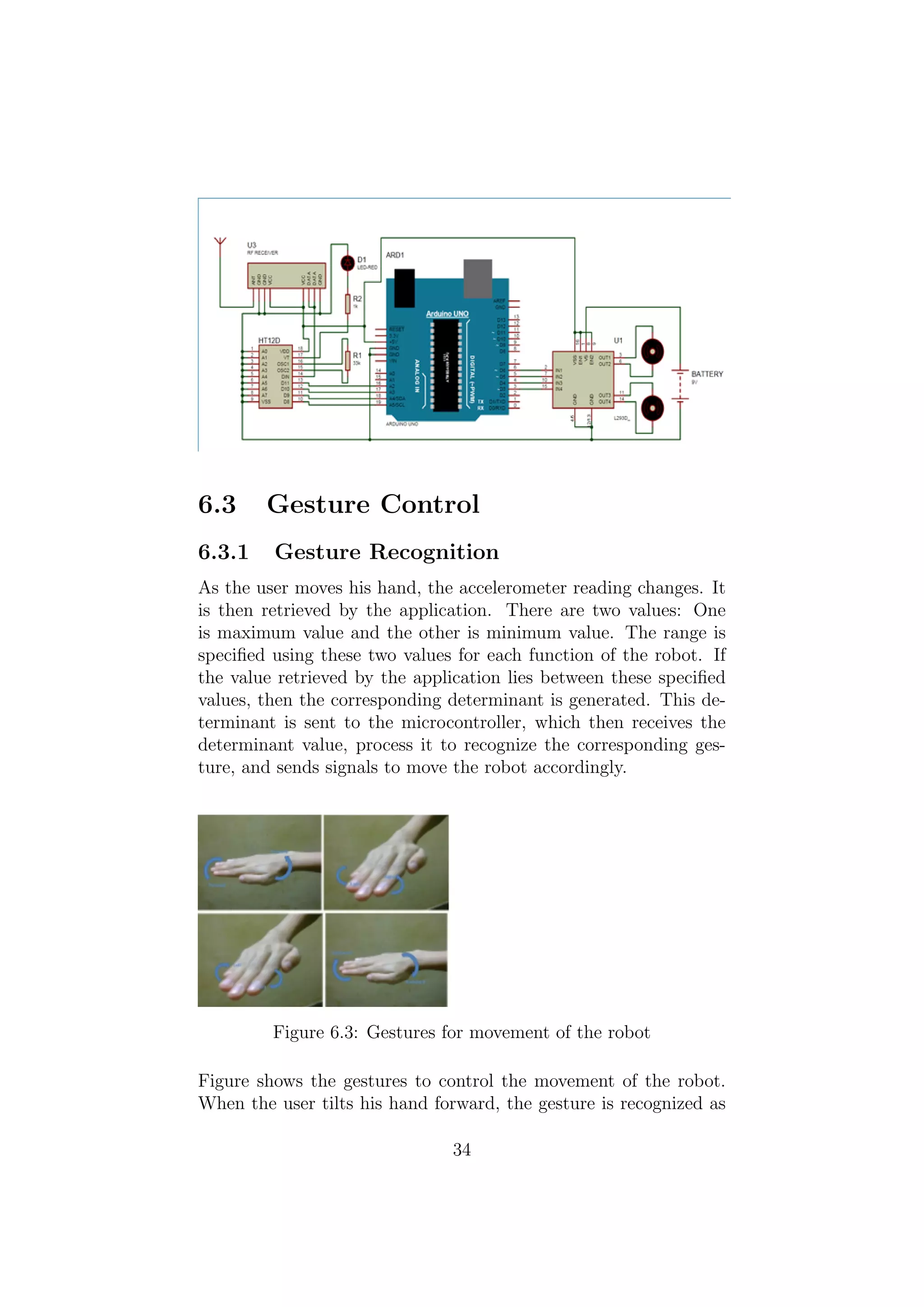
35.
6.3 Gesture Control
6.3.1Gesture Recognition
As the user moves his hand, the accelerometer reading changes. It
is then retrieved by the application. There are two values: One
is maximum value and the other is minimum value. The range is
specified using these two values for each function of the robot. If
the value retrieved by the application lies between these specified
values, then the corresponding determinant is generated. This de-
terminant is sent to the microcontroller, which then receives the
determinant value, process it to recognize the corresponding ges-
ture, and sends signals to move the robot accordingly.
Figure 6.3: Gestures for movement of the robot
Figure shows the gestures to control the movement of the robot.
When the user tilts his hand forward, the gesture is recognized as
34
36.
the forward movement,and the robot moves in the forward direc-
tion. The angle of the tilt or the difference between the angle of
tilt of users hand and the threshold value of forward movement
gesture determines the speed of the robot. When the user tilts his
hand on the right direction, the gesture is recognized as the right
turn, and the robot moves in the right direction. When the user
tilts his hand in the left direction, the gesture is recognized as the
left turn, and the robot moves in the right direction. The angle of
the tilt of users hand determines whether the left or right turn is
a normal turn or a sharp turn. A sharp turn is one in which a car
changes direction without slowing down before turning. When the
user tilts his hand backwards, the gesture is recognized as the move
backward gesture, and the robot moves in the backward direction.
If the users hand is somewhere between the two gestures, i.e., the
accelerometer value is somewhere between the threshold of two di-
rections(forward and left turn, left turn and backwards, backwards
and right turn, forward and right turn), then the robot moves in
that diagonal direction.
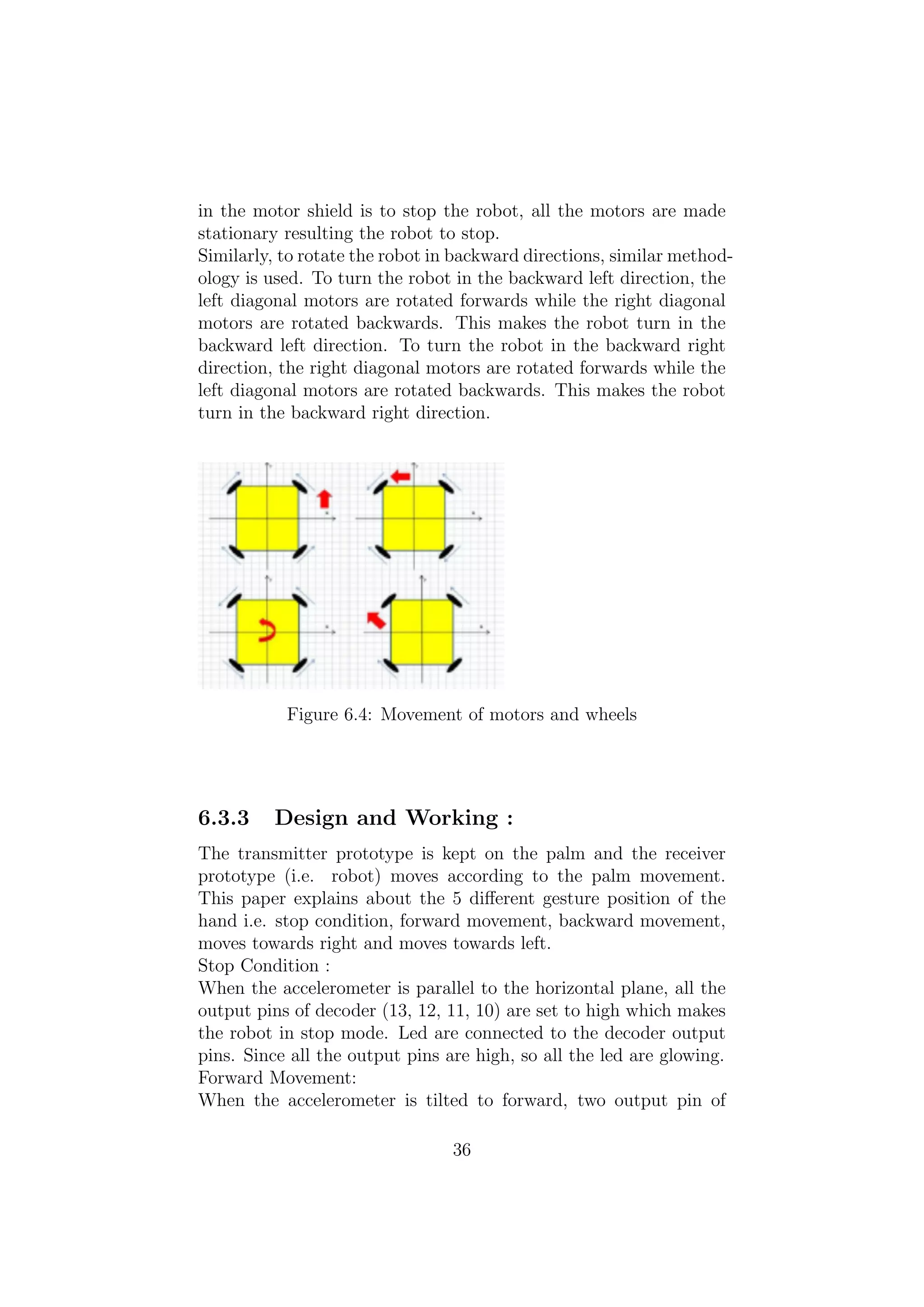
6.3.2 Movement of Motors and Wheels
There are three DC motors used in the design of this robot: one
motor for each wheel. The functions are called from the program
burnt in the Arduino microcontroller. The signal is sent to the mo-
tor shield that runs the motors.
The wheels are connected to the motors. 3 DC motors are used Two
for left wheels, and two for right wheels. When the signal received
in the motor shield is to move forward, all the four wheels of motors
rotate forward, this turns all the four wheels in the forward direc-
tion. The robot moves in the forward direction. When the signal
received in the motor shield is to turn the robot in the forward left
direction, the left diagonal motors are rotated backwards while the
right diagonal motors are made rotated forwards. This makes the
robot turn in the forward left direction. When the signal received
in the motor shield is to turn the robot in the forward right di-
rection, the right diagonal motors are rotated backward while the
left diagonal motors are rotated forwards. This makes the robot
turn in the forward right direction. When the signal in the motor
shield is to move backward, both the pairs of the motors are rotated
backwards resulting the robot to move backwards. When the signal
35
37.
in the motorshield is to stop the robot, all the motors are made
stationary resulting the robot to stop.
Similarly, to rotate the robot in backward directions, similar method-
ology is used. To turn the robot in the backward left direction, the
left diagonal motors are rotated forwards while the right diagonal
motors are rotated backwards. This makes the robot turn in the
backward left direction. To turn the robot in the backward right
direction, the right diagonal motors are rotated forwards while the
left diagonal motors are rotated backwards. This makes the robot
turn in the backward right direction.
Figure 6.4: Movement of motors and wheels
6.3.3 Design and Working :
The transmitter prototype is kept on the palm and the receiver
prototype (i.e. robot) moves according to the palm movement.
This paper explains about the 5 different gesture position of the
hand i.e. stop condition, forward movement, backward movement,
moves towards right and moves towards left.
Stop Condition :
When the accelerometer is parallel to the horizontal plane, all the
output pins of decoder (13, 12, 11, 10) are set to high which makes
the robot in stop mode. Led are connected to the decoder output
pins. Since all the output pins are high, so all the led are glowing.
Forward Movement:
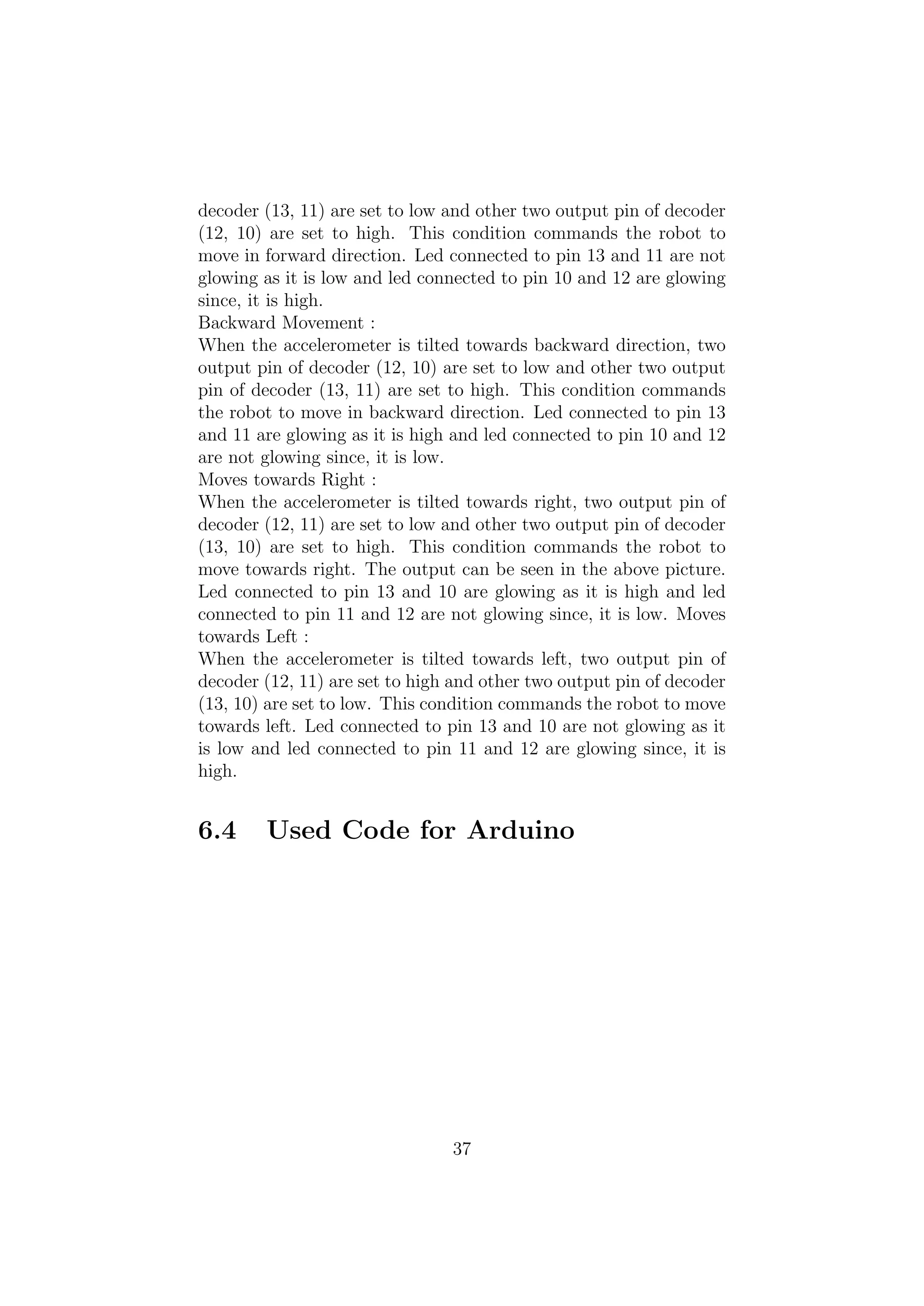
When the accelerometer is tilted to forward, two output pin of
36
38.
decoder (13, 11)are set to low and other two output pin of decoder
(12, 10) are set to high. This condition commands the robot to
move in forward direction. Led connected to pin 13 and 11 are not
glowing as it is low and led connected to pin 10 and 12 are glowing
since, it is high.
Backward Movement :
When the accelerometer is tilted towards backward direction, two
output pin of decoder (12, 10) are set to low and other two output
pin of decoder (13, 11) are set to high. This condition commands
the robot to move in backward direction. Led connected to pin 13
and 11 are glowing as it is high and led connected to pin 10 and 12
are not glowing since, it is low.
Moves towards Right :
When the accelerometer is tilted towards right, two output pin of
decoder (12, 11) are set to low and other two output pin of decoder
(13, 10) are set to high. This condition commands the robot to
move towards right. The output can be seen in the above picture.
Led connected to pin 13 and 10 are glowing as it is high and led
connected to pin 11 and 12 are not glowing since, it is low. Moves
towards Left :
When the accelerometer is tilted towards left, two output pin of
decoder (12, 11) are set to high and other two output pin of decoder
(13, 10) are set to low. This condition commands the robot to move
towards left. Led connected to pin 13 and 10 are not glowing as it
is low and led connected to pin 11 and 12 are glowing since, it is
high.
6.4 Used Code for Arduino
37
39.
Chapter 7
CONCLUSION,
LIMITATIONS AND
FUTUREWORK
7.1 Conclusion
We have gone through several hurdles and at the end we are able to
complete the project work.The project finally ran as our expectetion
was.It showed all the proper movements.
7.2 Limitations and Future Work
• The on-board batteries occupy a lot of space and are also
quite heavy. We can either use some alternate power source
for the batteries or replace the current DC Motors with ones
which require less power.
• Secondly, as we are using RF for wireless transmission, the
range is quite limited; nearly 50-80m. This problem can be
solved by utilizing a GSM module for wireless transmission.
The GSM infrastructure is installed almost all over the world.
GSM will not only provide wireless connectivity but also quite
a large range.
• Thirdly, an on-board camera can be installed for monitoring
the robot from faraway places.
38
40.
Chapter 8
FEASIBILITY OFTHE
PROJECT
During the development of the project we researched the feasibility
in different fields, especially software and hardware. The feasibility
study is shown below.
8.1 Software
We targeted to choose a language that is easy to understand and
program. So we chose assembly language for our project. Assembly
language is the basic language of microcontrollers. Although its
not user friendly in terms of programming but still one can learn it
quickly.
8.2 Hardware
We chose accelerometer as the sensing device because it records
even the minute movements. We could also have completed our
project using Arduino but chose microcontroller instead because its
cost is low and is easily available everywhere. There are a number
of dc geared motors available but the ones we chose are capable of
supporting loads up to 6kgs.
39
41.
8.3 Economic
This projectis quite cost effective. The components used are easily
available in the market apart from accelerometer, RF modules and
the motors. These components are quite cheap as compared to the
motors which are the only expensive part in our whole project. But
these particular motors are capable of providing support to loads
up to 6kgs which is what we wanted.
40


![ANPARA THERMAL POWER STATION[1] sangam.pdf](https://cdn.slidesharecdn.com/ss_thumbnails/anparathermalpowerstation1sangam-251121115219-9261cde4-thumbnail.jpg?width=640&height=640&fit=bounds)


