What is Microprocessor
2
�A microprocessor,sometimes called a logic chip,
is a computer processor on a microchip.
� It is also called as “Heart of Computer.”
� The microprocessor contains all,or most of, the
central processing unit (CPU) functions.
� A microprocessor is designed to perform
arithmetic and logic operations that make use of
small number-holding areas called registers.
3.
� Typical microprocessoroperations include
adding, subtracting, comparing two
numbers, and fetching numbers from
one area to another.
� These operations are the result of a set of
instructions that are part of the
microprocessor design.
3
4.
Three basic characteristicsdifferentiate
microprocessors:
4
� Instruction set: The set of instructions that the
microprocessor can execute.
� Bandwidth : The number of bits processed in a single
instruction.
� Clock speed : Given in megahertz (MHz), the clock
speed determines how many instructions per second the
processor can execute.
In both cases, the higher the value, the more powerful the
CPU.
For example, a 32-bit microprocessor that runs at
50MHz is more powerful than a 16-bit microprocessor
that runs at 25MHz.
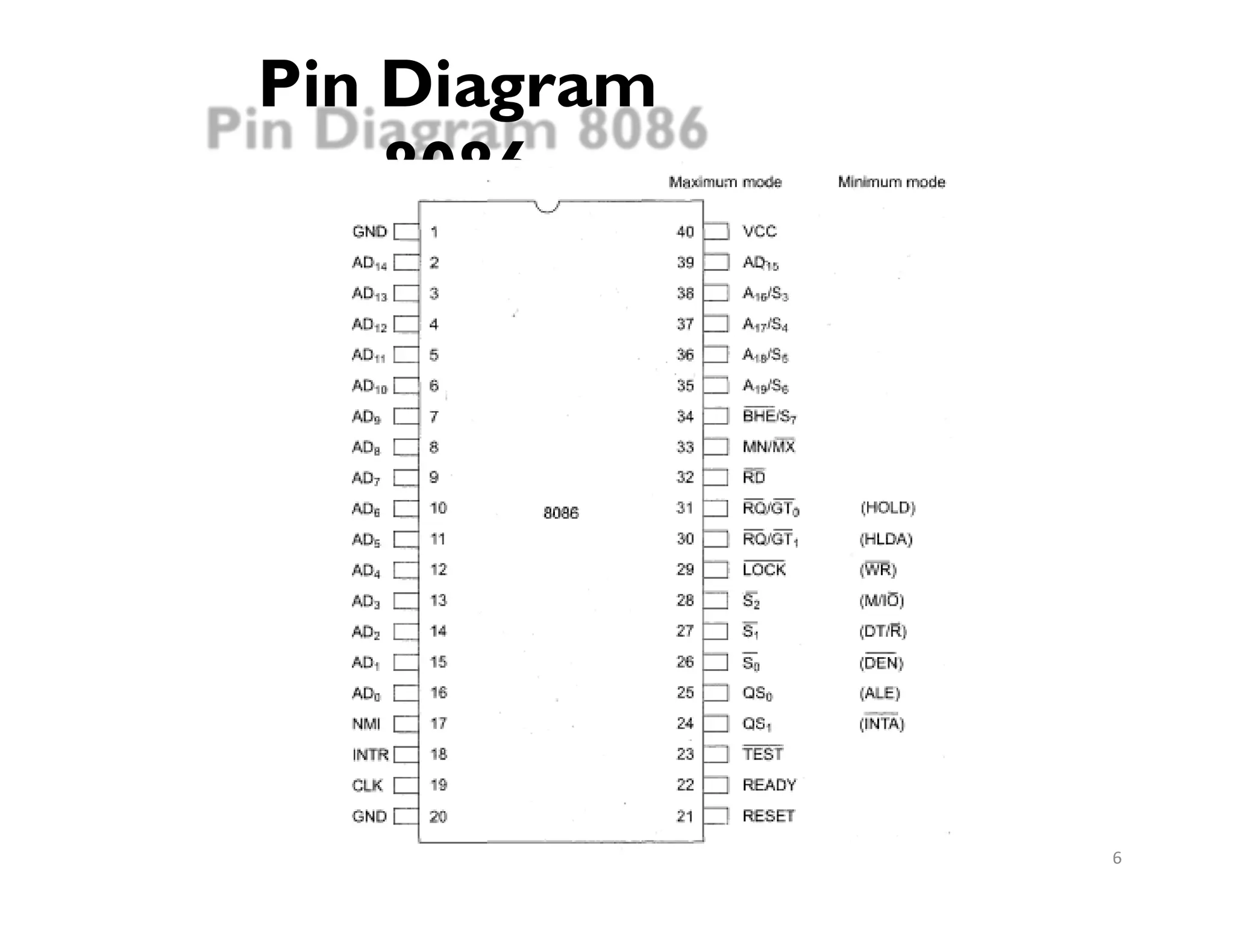
�8086 can bework in two modes
� Minimum Mode: For single processor
systems.
� Maximum Mode: For system with two or more
processors.
�Depending upon modes signals can be
divided into
� Signals having common functions in both modes
� Signals for Minimum Mode
� Signals for Maximum Mode
7
8.
Logical to physicaladdress
Translation in 8086
8
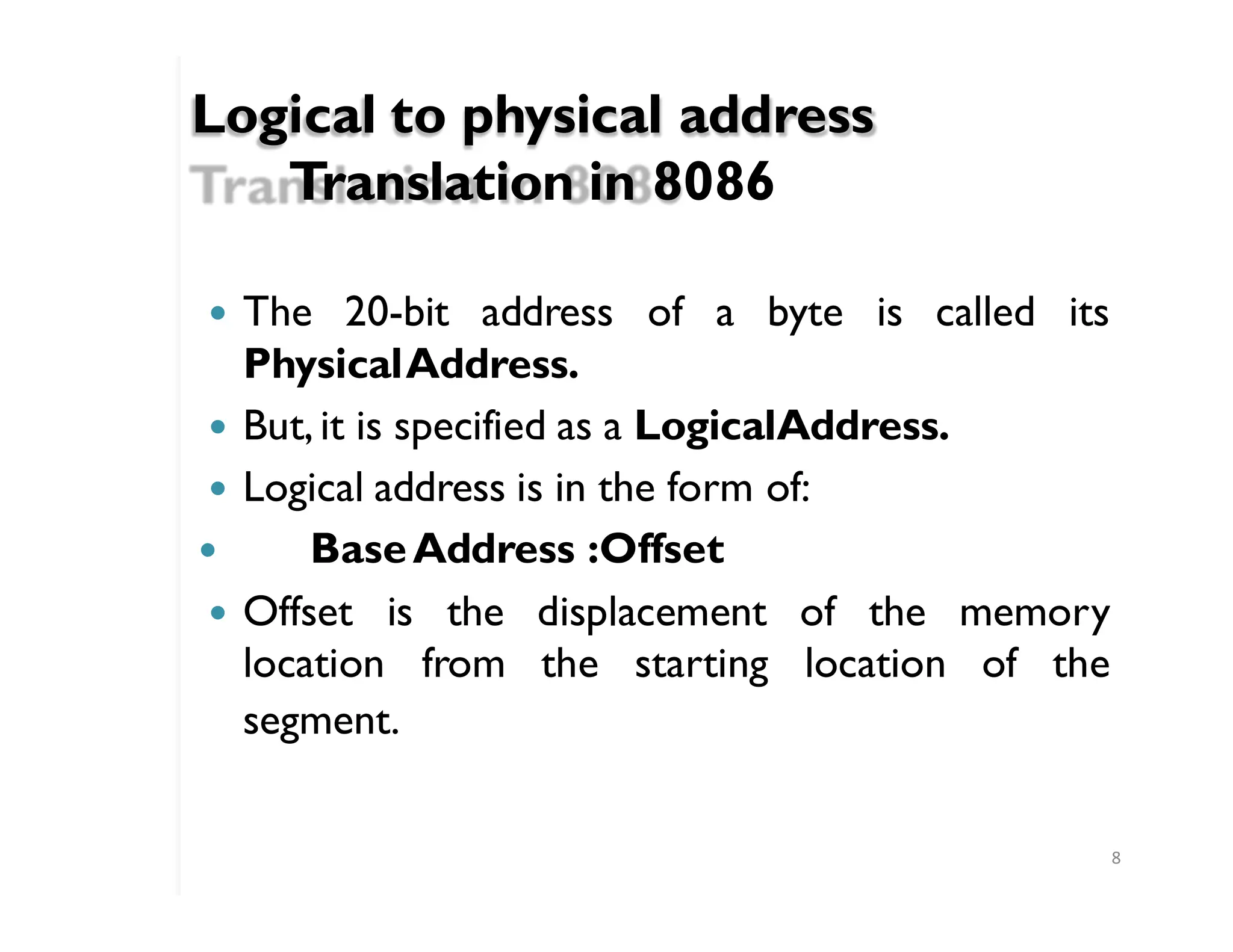
� Offset is the displacement of the memory
location from the starting location of the
� The 20-bit address of a byte is called its
PhysicalAddress.
� But,it is specified as a LogicalAddress.
� Logical address is in the form of:
� BaseAddress :Offset
segment.
9.
Example
9
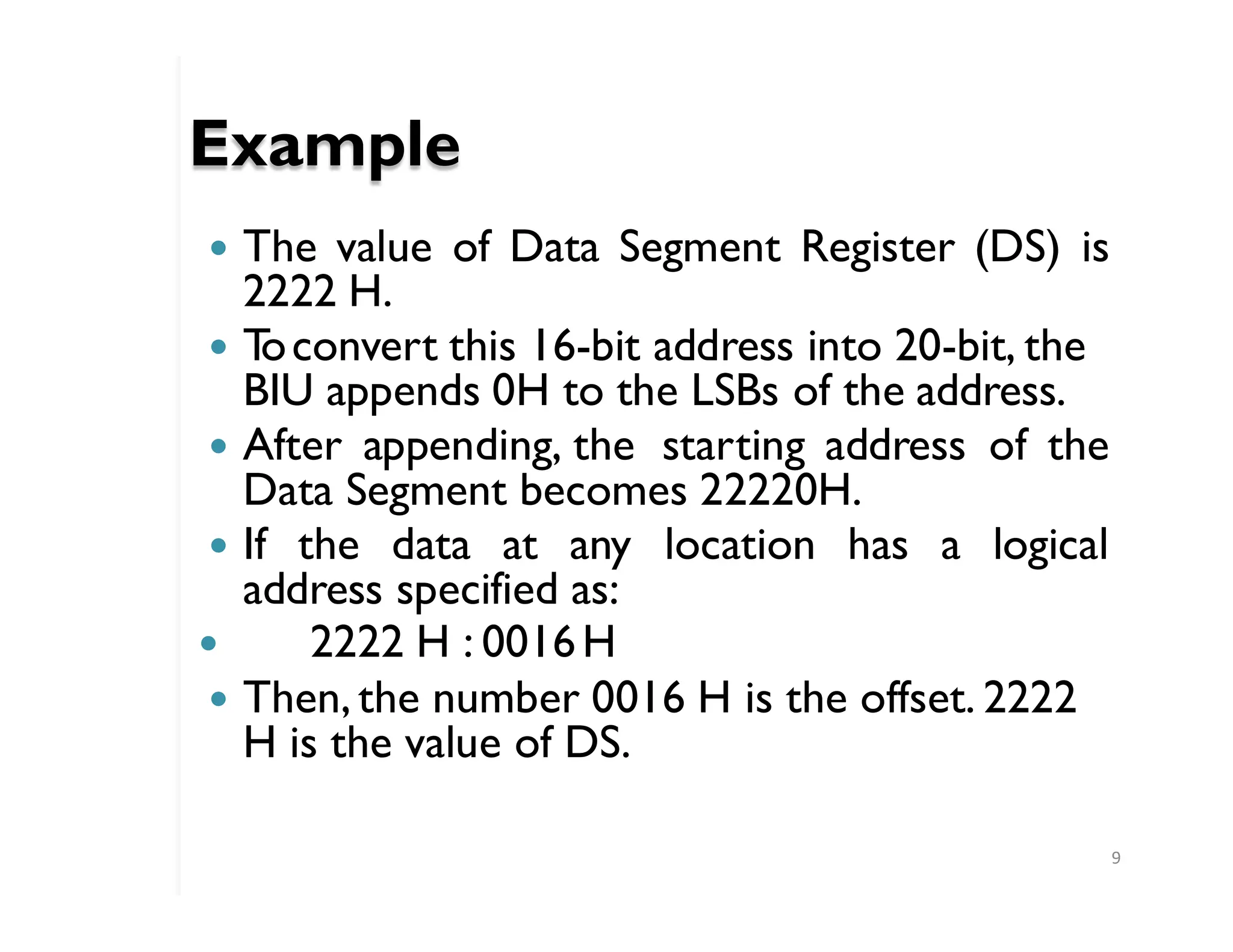
� The valueof Data Segment Register (DS) is
2222 H.
� T
oconvert this 16-bit address into 20-bit, the
BIU appends 0H to the LSBs of the address.
� After appending, the starting address of the
Data Segment becomes 22220H.
� If the data at any location has a logical
address specified as:
� 2222 H : 0016H
� Then,the number 0016 H is the offset. 2222
H is the value of DS.
10.
T
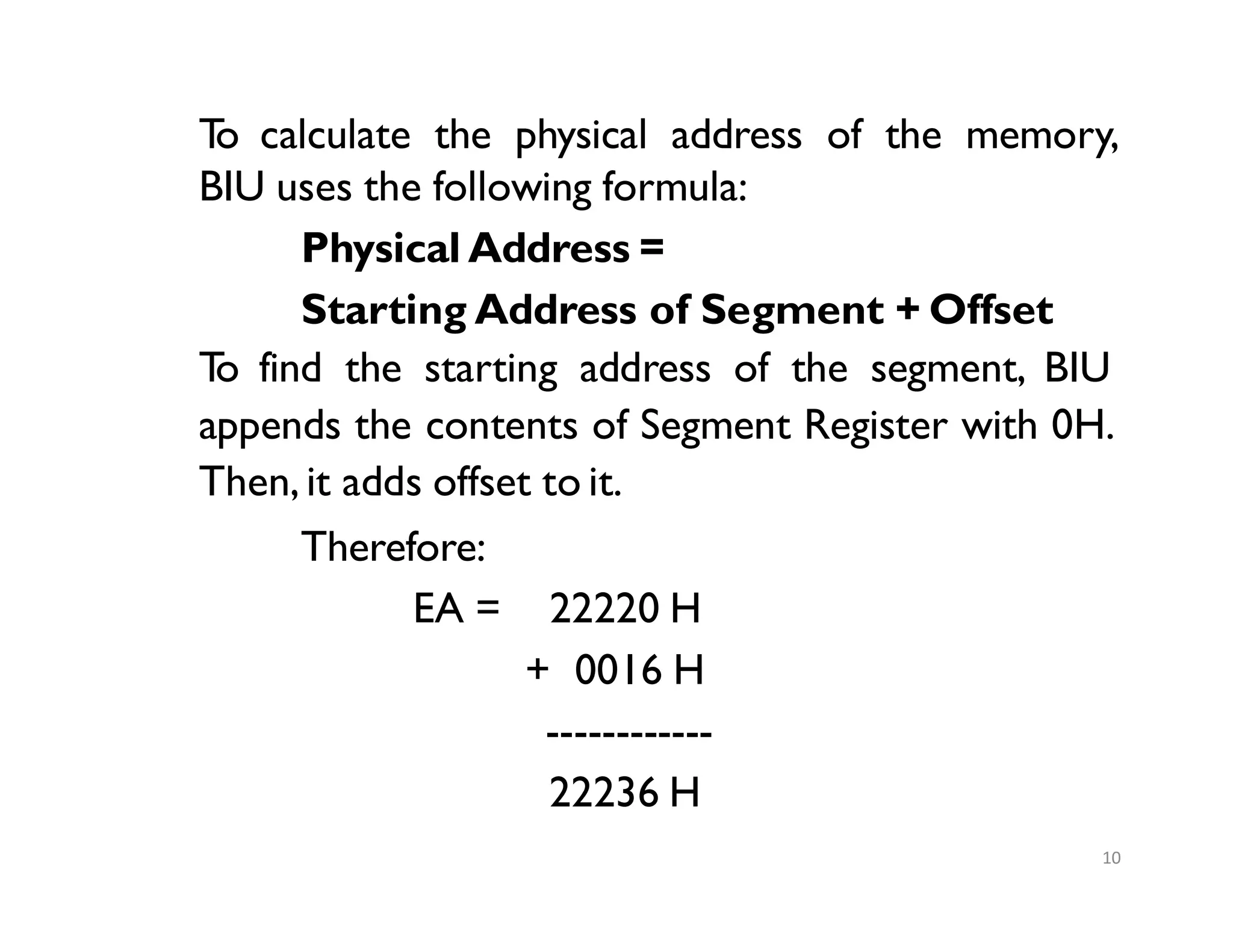
o calculate thephysical address of the memory,
BIU uses the following formula:
Physical Address =
Starting Address of Segment + Offset
T
o find the starting address of the segment, BIU
appends the contents of Segment Register with 0H.
Then, it adds offset to it.
Therefore:
EA = 22220 H
+ 0016 H
------------
22236 H
10
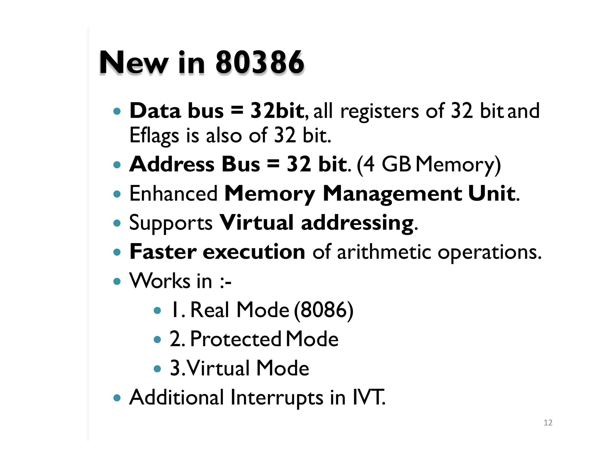
New in 80386
12
�Data bus = 32bit, all registers of 32 bitand
Eflags is also of 32 bit.
� Address Bus = 32 bit. (4 GB Memory)
� Enhanced Memory Management Unit.
� Supports Virtual addressing.
� Faster execution of arithmetic operations.
� Works in :-
� 1. Real Mode (8086)
� 2. ProtectedMode
� 3.Virtual Mode
� Additional Interrupts in IVT.
13.
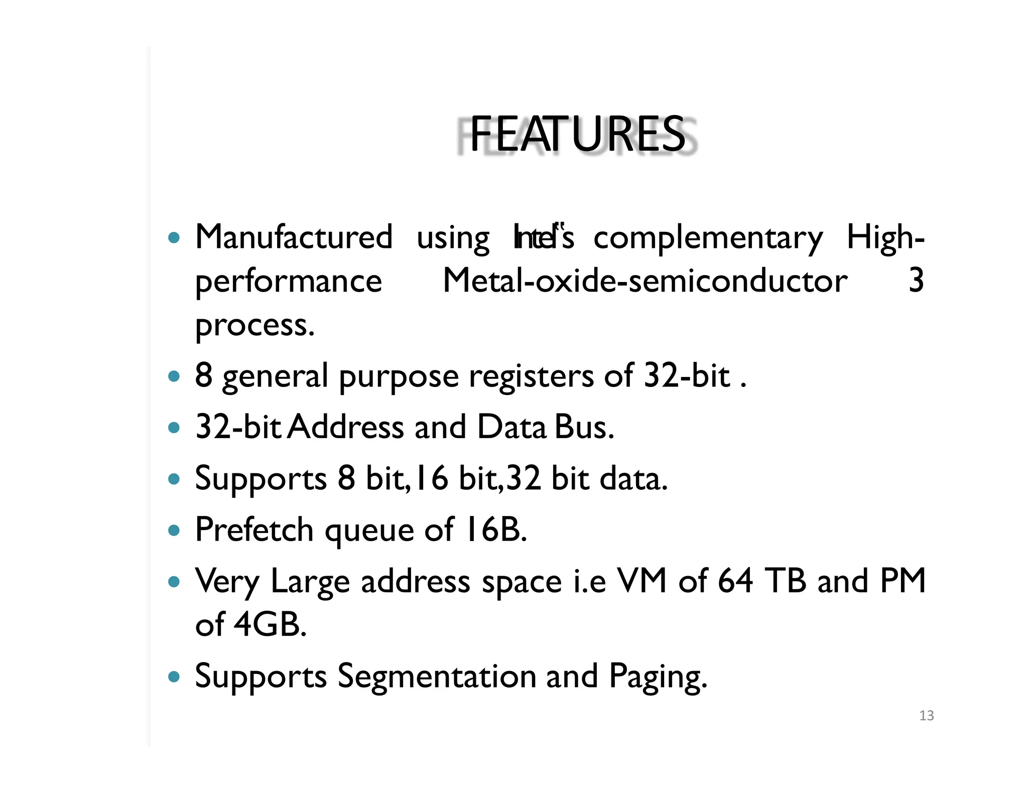
FEATURES
13
� Manufactured usingIntel‟s complementary High-
performance Metal-oxide-semiconductor 3
process.
� 8 general purpose registers of 32-bit .
� 32-bitAddress and Data Bus.
� Supports 8 bit,16 bit,32 bit data.
� Prefetch queue of 16B.
� Very Large address space i.e VM of 64 TB and PM
of 4GB.
� Supports Segmentation and Paging.
14.
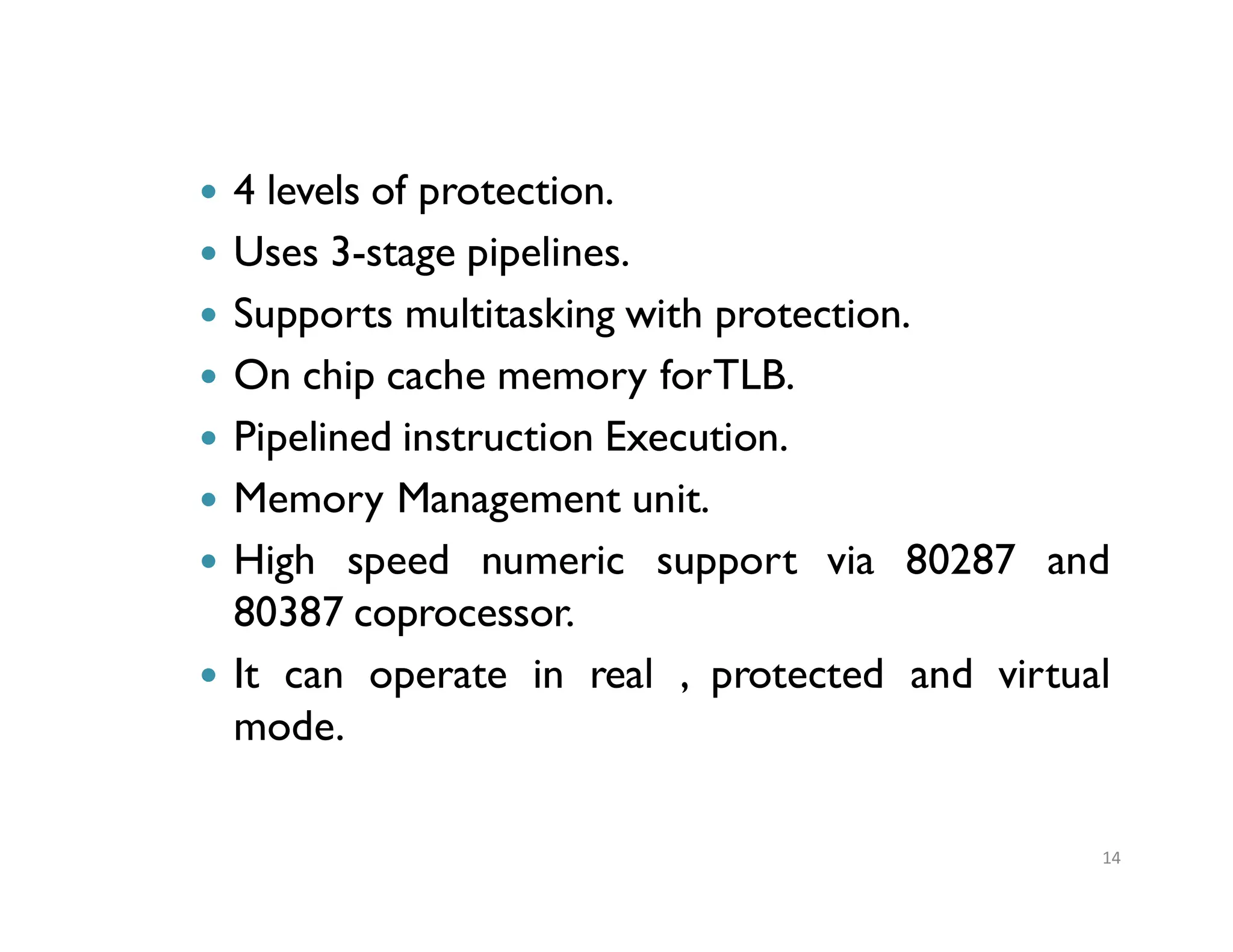
� 4 levelsof protection.
� Uses 3-stage pipelines.
� Supports multitasking with protection.
� On chip cache memory forTLB.
� Pipelined instruction Execution.
� Memory Management unit.
� High speed numeric support via 80287 and
80387 coprocessor.
� It can operate in real , protected and virtual
mode.
14
15.
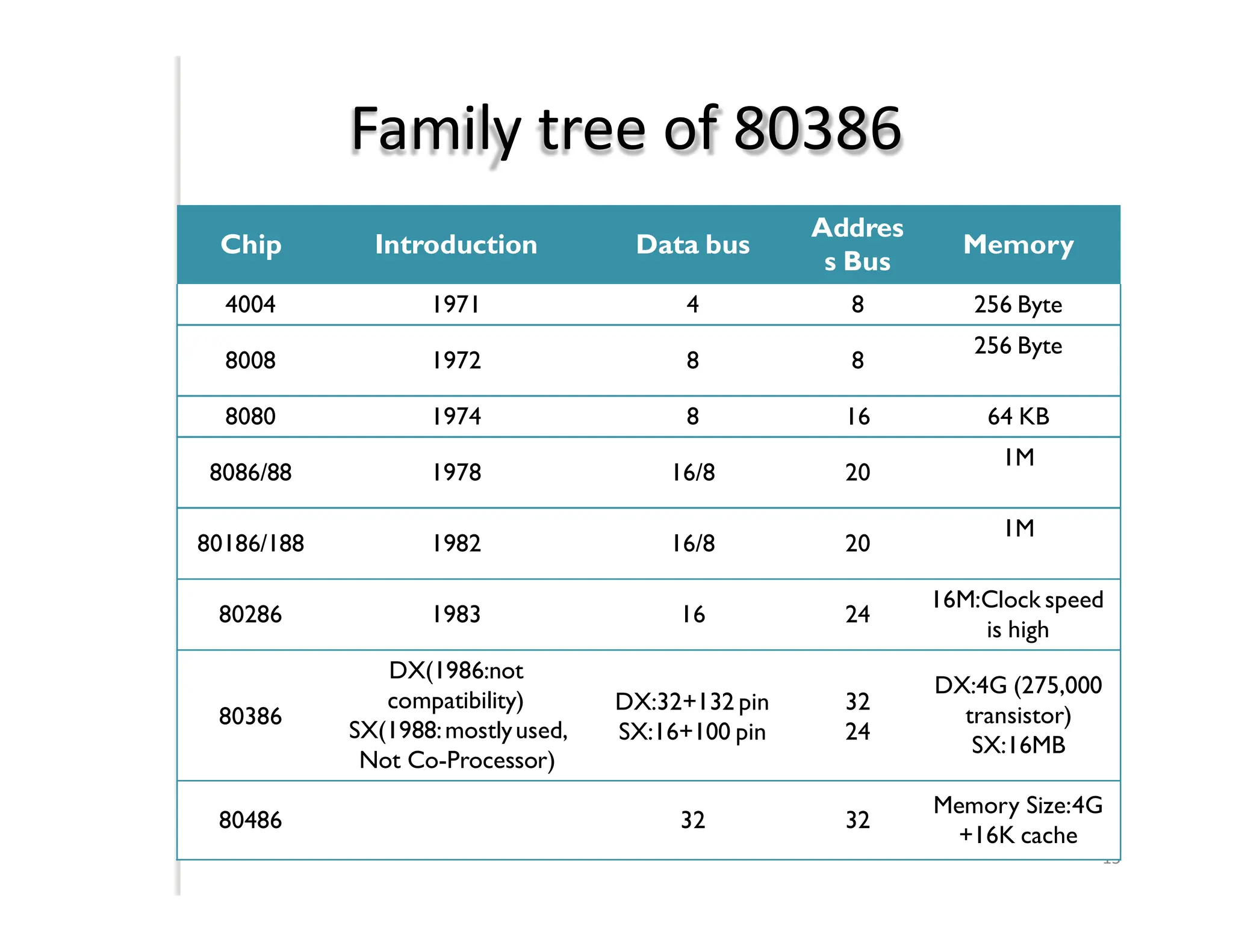
Family tree of80386
15
Chip Introduction Data bus
Addres
s Bus
Memory
4004 1971 4 8 256 Byte
8008 1972 8 8
256 Byte
8080 1974 8 16 64 KB
8086/88 1978 16/8 20
1M
80186/188 1982 16/8 20
1M
80286 1983 16 24
16M:Clock speed
is high
80386
DX(1986:not
compatibility)
SX(1988:mostlyused,
Not Co-Processor)
DX:32+132 pin
SX:16+100 pin
32
24
DX:4G (275,000
transistor)
SX:16MB
80486 32 32
Memory Size:4G
+16K cache
16.
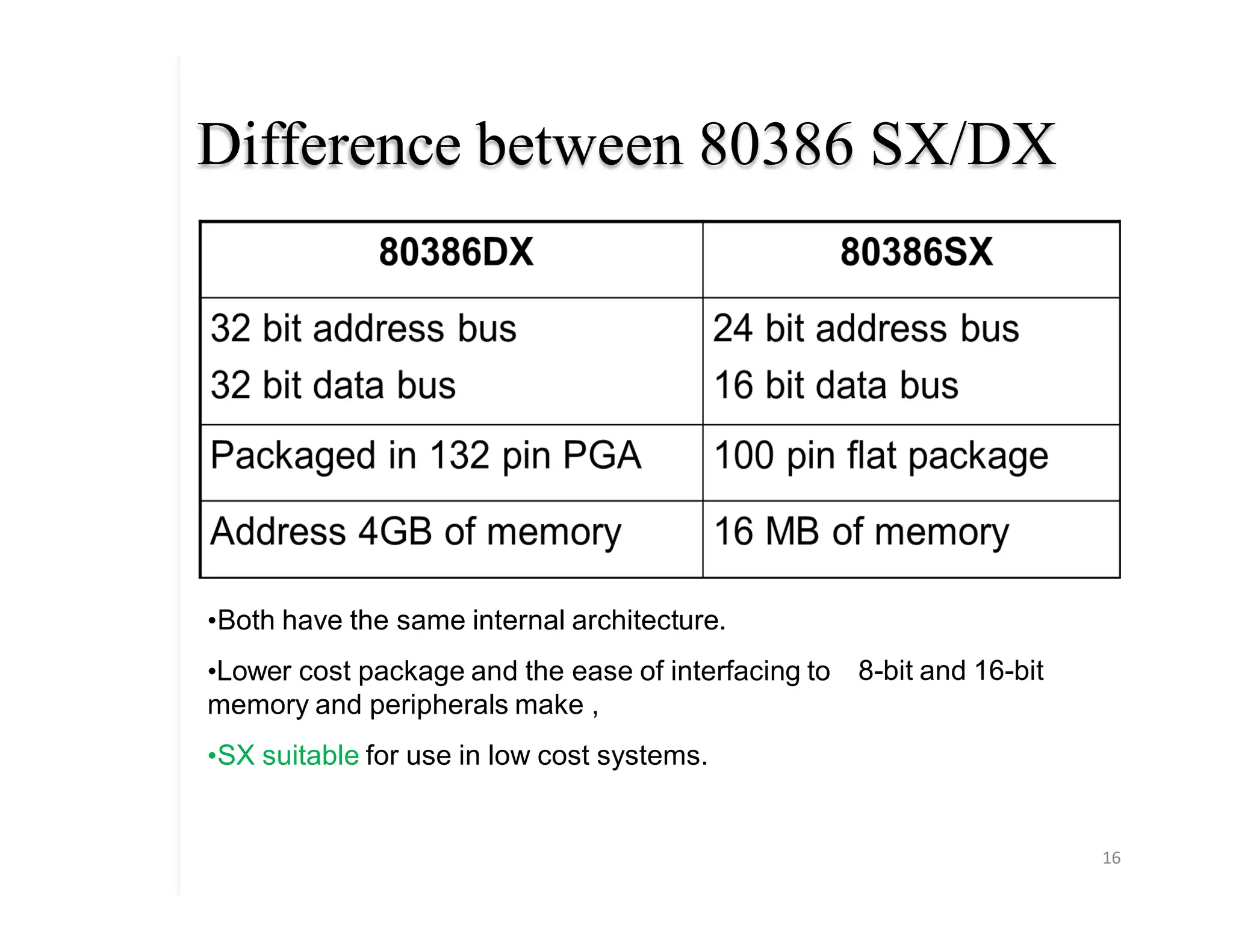
Difference between 80386SX/DX
16
8-bit and 16-bit
•Both have the same internal architecture.
•Lower cost package and the ease of interfacing to
memory and peripherals make ,
•SX suitable for use in low cost systems.
17.
Introduction to 80386
17
oThe 80386 is an advanced 32-bit microprocessor optimized
for multitasking operating systems and designed for
applications needing very high performance.
o The 32-bit registers and data paths support 32-bit addresses
and data types.
o The processor can address up to 4 gigabytes of physical
memory and 64 terabytes (246 bytes) of virtual memory.
o The on-chip memory management facilities include address
translation registers, advanced multitasking hardware, a
protection mechanism, and paged virtual memory.
o Special debugging registers provide data and code
breakpoints even in ROM-based software.
18.
Features of 80386
18
�The 80386 has three processing modes:
� 1. ProtectedMode:
o Protected mode is the natural 32-bit environment of the 80386
processor.
o In this mode all instructions and features are available.
� 2.Real-Address Mode.
o Real-address mode is the mode of the processor immediate after
RESET.
o In real mode the 80386 appears to programmers as a fast 8086 with
some new instructions.
o Most applications of the 80386 will use real mode.
� 3.Virtual 8086 Mode:
o Virtual 8086 mode is a dynamic mode which can switch repeatedly and
rapidly betweenV86 mode and protected mode.
o The CPU entersV86 mode from protected then leavesV86 mode and
enters protected.
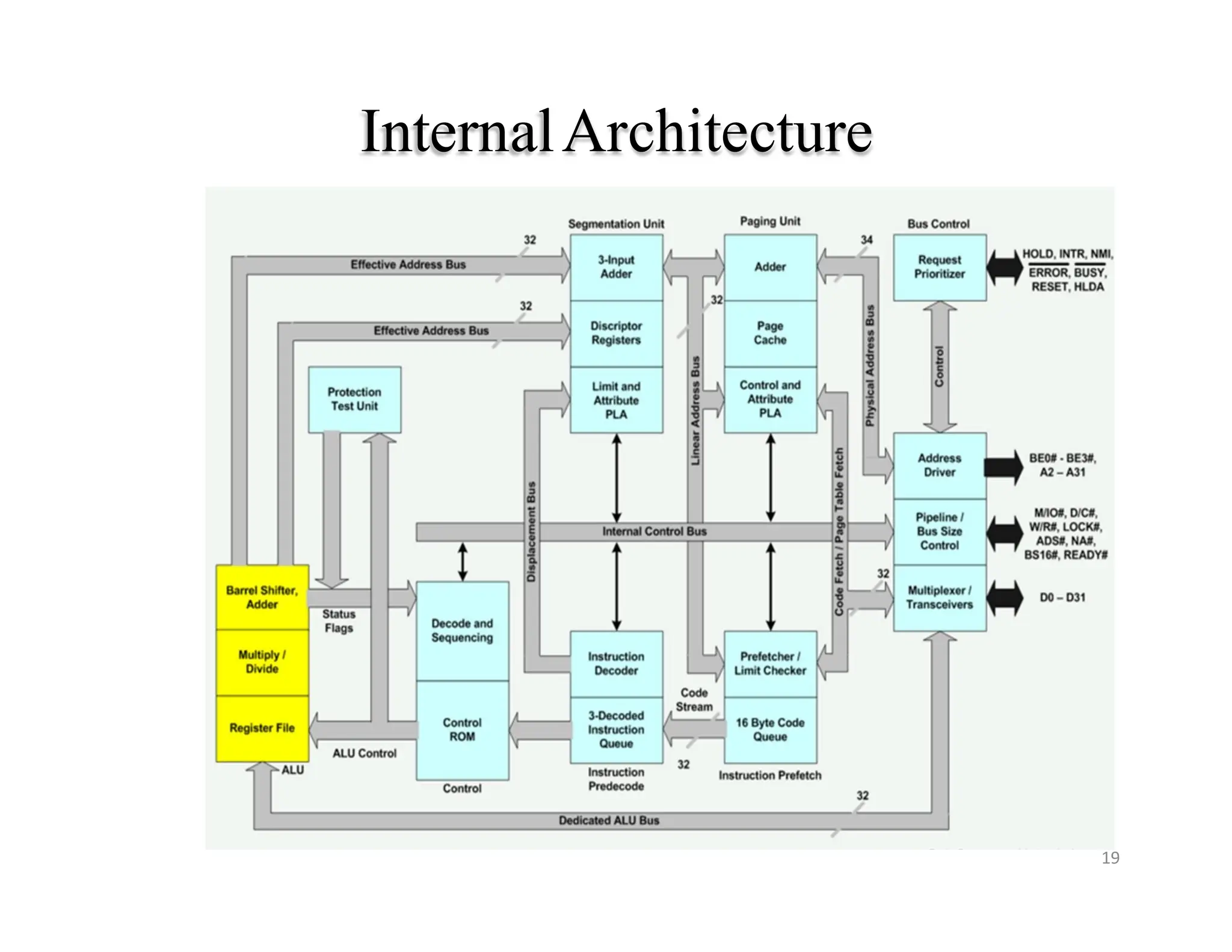
Architecture of 80386
20
�The Internal Architecture of 80386 is divided into 3
sections:
◦ i) Central processing unit (CPU)
� Execution unit (EU) and
� Instruction unit (IU)
◦ ii) Memory management unit (MMU)
� Segmentation unit
� Paging unit.
◦ iii) Bus interface unit( BIU)
21.
Central Processing Unit
21
�Central processing unit is further divided into
Execution unit and Instruction unit.
• Execution unit has 8 General purpose and 8 Special
purpose registers which are either used for handling
data or calculating offset addresses.
� The Instruction unit decodes the opcode bytes
received from the 16-byte instruction code queue
and arranges them in a 3- instruction decoded
instruction queue.
22.
� After decodingthem pass it to the control
section for deriving the necessary control
signals. The barrel shifter increases the
speed of all shift and rotate operations.
• The multiply / divide logic implements the
bit-shift-rotate algorithms to complete the
operations in minimum time.
• Even 32- bit multiplications can be executed
within one microsecond by the multiply /
divide logic.
22
23.
Memory Management Unit
23
�The Memory management unit consists of a
Segmentation unit and a Paging unit.
� Segmentation unit allows the use of two
address components, viz. segment and offset
for relocability and sharing of code and data.
� Segmentation unit allows segments of size
4Gbytes at max.
24.
� The Pagingunit organizes the physical
memory in terms of pages of 4 kbytes size
each.
� Paging unit works under the control of the
segmentation unit, i.e. each segment is further
divided into pages.
� The virtual memory is also organizes in terms
of segments and pages by the memory
management unit.
24
25.
� The Segmentationunit provides a 4 level protection
mechanism for protecting and isolating the system
code and data from those of the application program.
� Paging unit converts linear addresses into physical
addresses.
� The control and attribute PLA checks the privileges
at the page level. Each of the pages maintains the
paging information of the task.
� The limit and attribute PLA checks segment limits
and attributes at segment level to avoid invalid
accesses to code and data in the memory segments.
25
26.
Bus Interface Unit
26
�The Bus control unit has a prioritizer to resolve
the priority of the various bus requests.
� This controls the access of the bus. The address
driver drives the bus enable and address signal A0–
A31.
� The pipeline and dynamic bus sizing unit handle
the related control signals.
� The data buffers interface the internal data bus
with the system bus.
27.
MEMORY ORGANIZATIONAND
SEGMENTATION
27
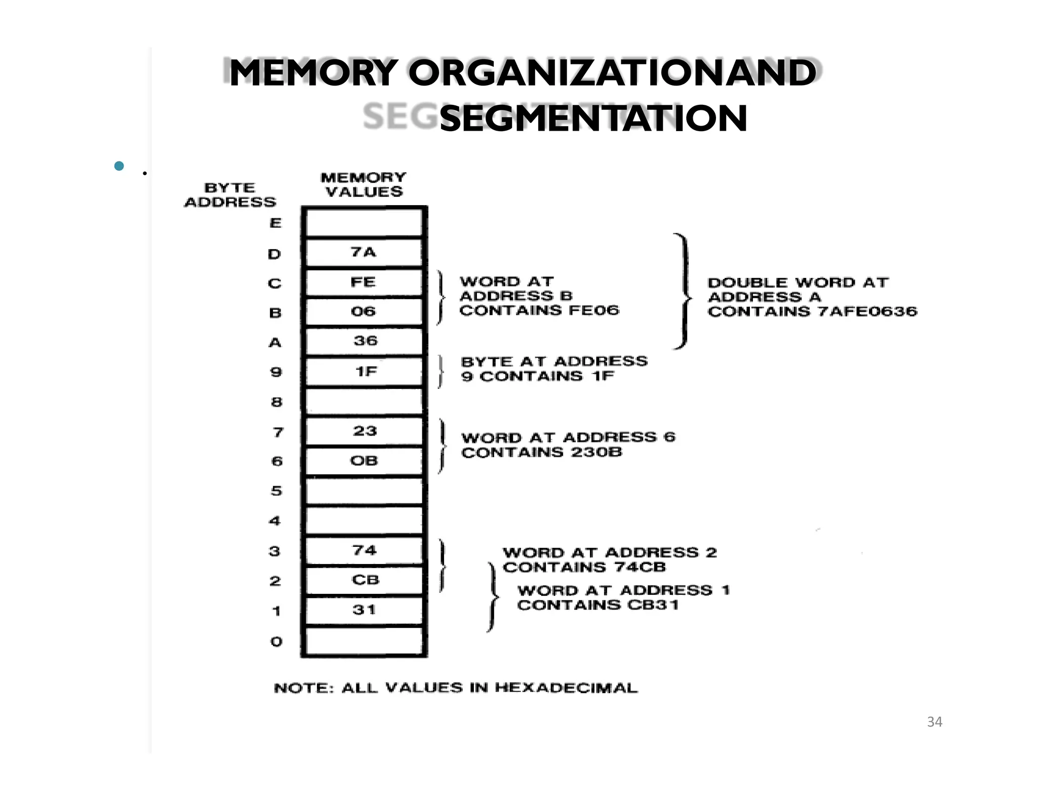
� Thephysical memory of an 80386 system is organized as a
sequence of 8-bit bytes.
� Each byte is assigned a unique address that ranges from
0 to a maximum of 232 -1.(4 Gigabytes).
� The model of memory organization determined by
systems-software designers.
� T
womodel of memory
� 1. Flat model:single array of up to 4 GB.
� A pointer into this flat address space is a 32-bit ordinal
number that may range from 0 to 232 -1.
28.
MEMORY ORGANIZATIONAND
SEGMENTATION
28
linear
� Segmentedmodel: collection of up to 16,383
address spaces.
� Viewed by an applications program (called the logical
address space)
� The processor maps the 64 terabyte logical address space
onto the physical address space (4 GB) by the address
translation mechanisms.
� Each of these linear subspaces is called a segment.
� A segment is a unit of contiguous address space
� Segment sizes may range from 1 byte up to a maximum of
232 bytes (4 gigabytes).
�
29.
MEMORY ORGANIZATIONAND
SEGMENTATION
29
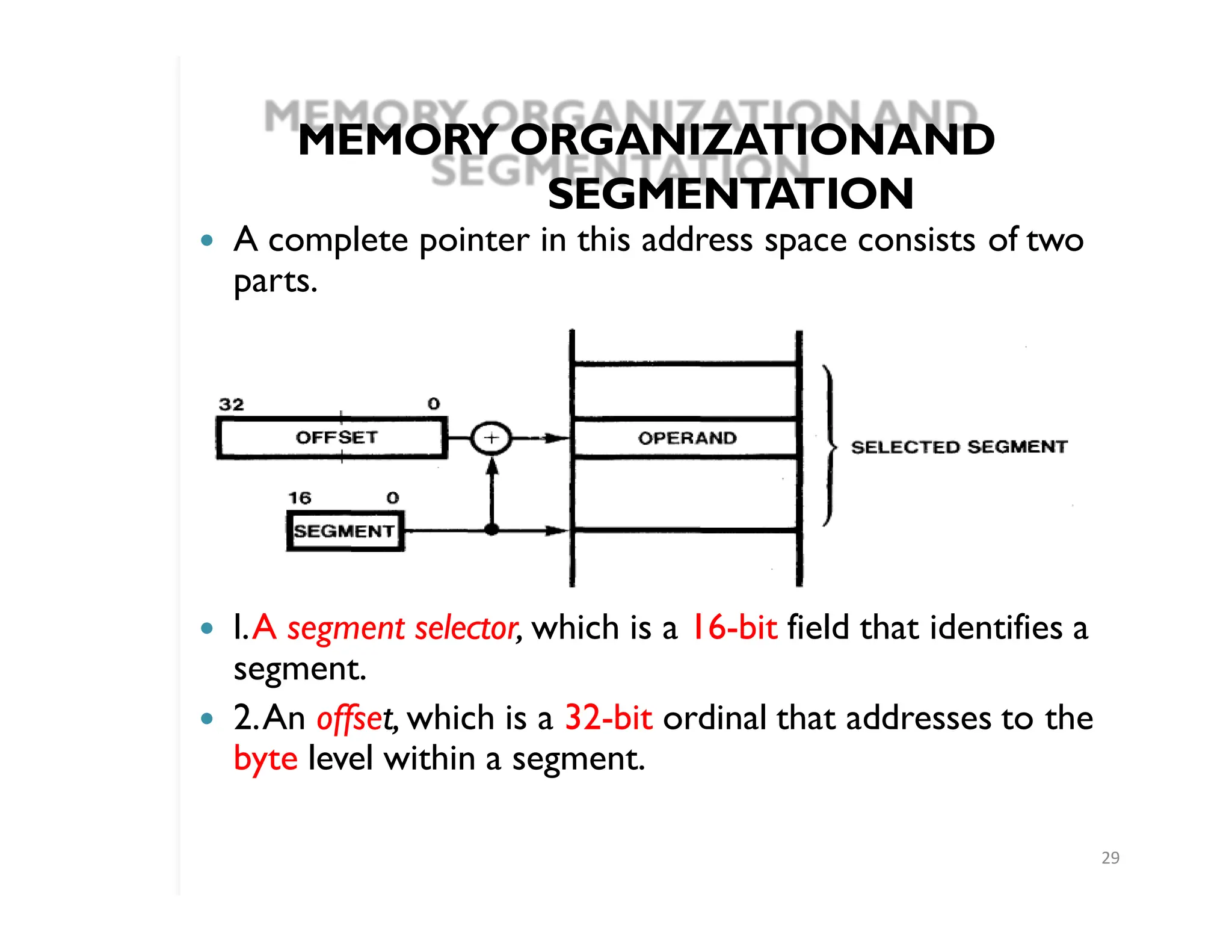
� Acomplete pointer in this address space consists of two
parts.
� l.A segment selector, which is a 16-bit field that identifies a
segment.
� 2.An offset, which is a 32-bit ordinal that addresses to the
byte level within a segment.
30.
Data
Types:
30
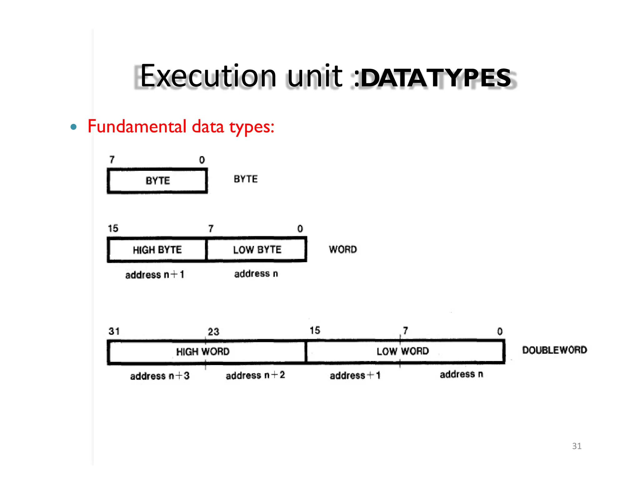
� Bytes, words,and doublewords are the fundamental
data types
� Integer: A signed binary numeric value contained in a 32-
bit doubleword,16-bit word, or 8-bit byte. All operations
assume a 2's complement representation.
- range of an 8-bit integer is -128 through +127
- 16-bit integers may range from -32,768 through +32,767
- 32-bit integers may range from -231 through +231-1
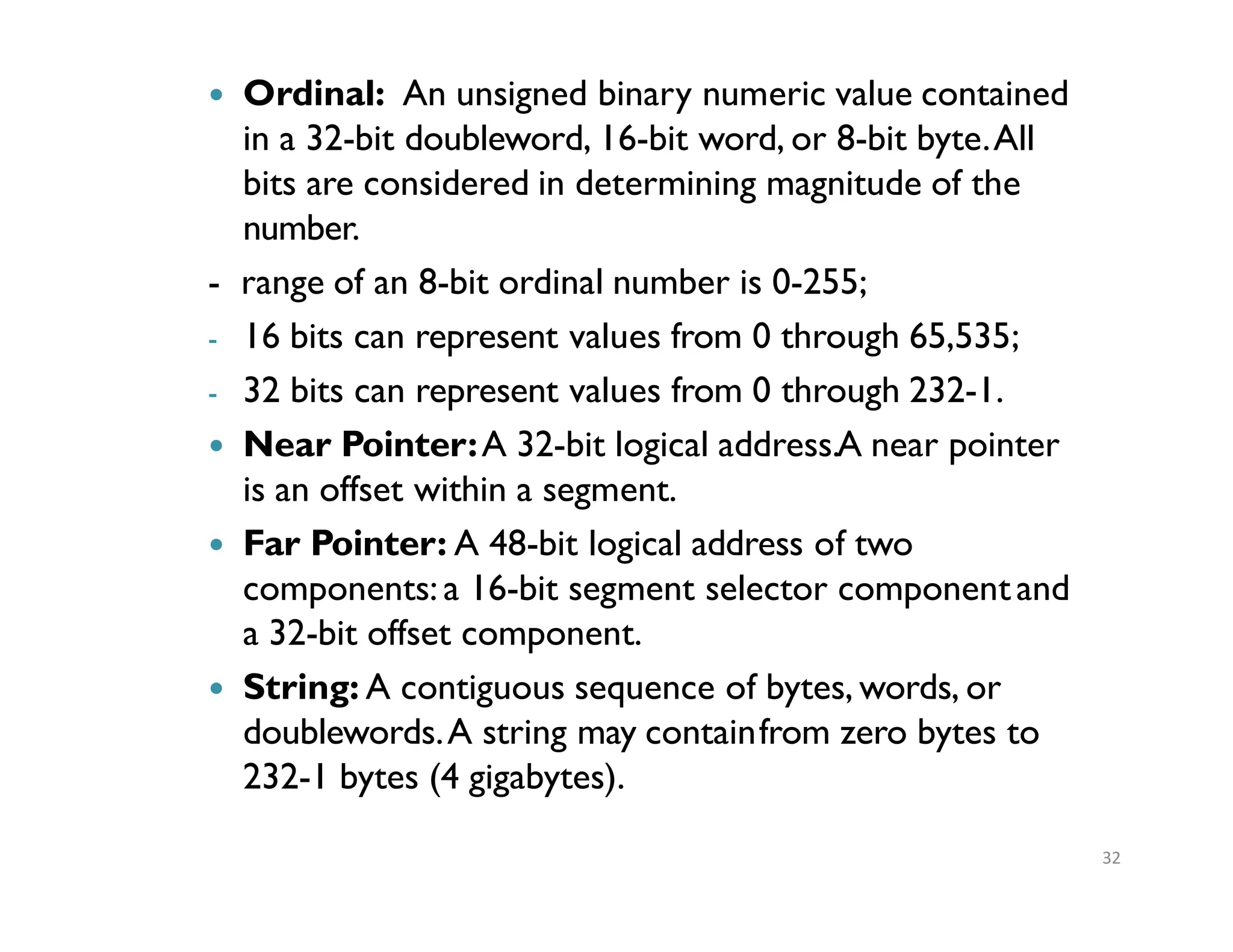
� Ordinal: Anunsigned binary numeric value contained
in a 32-bit doubleword, 16-bit word, or 8-bit byte.All
bits are considered in determining magnitude of the
number.
- range of an 8-bit ordinal number is 0-255;
- 16 bits can represent values from 0 through 65,535;
- 32 bits can represent values from 0 through 232-1.
� Near Pointer:A 32-bit logical address.A near pointer
is an offset within a segment.
� Far Pointer: A 48-bit logical address of two
components:a 16-bit segment selector componentand
a 32-bit offset component.
� String: A contiguous sequence of bytes, words, or
doublewords.A string may containfrom zero bytes to
232-1 bytes (4 gigabytes).
32
33.
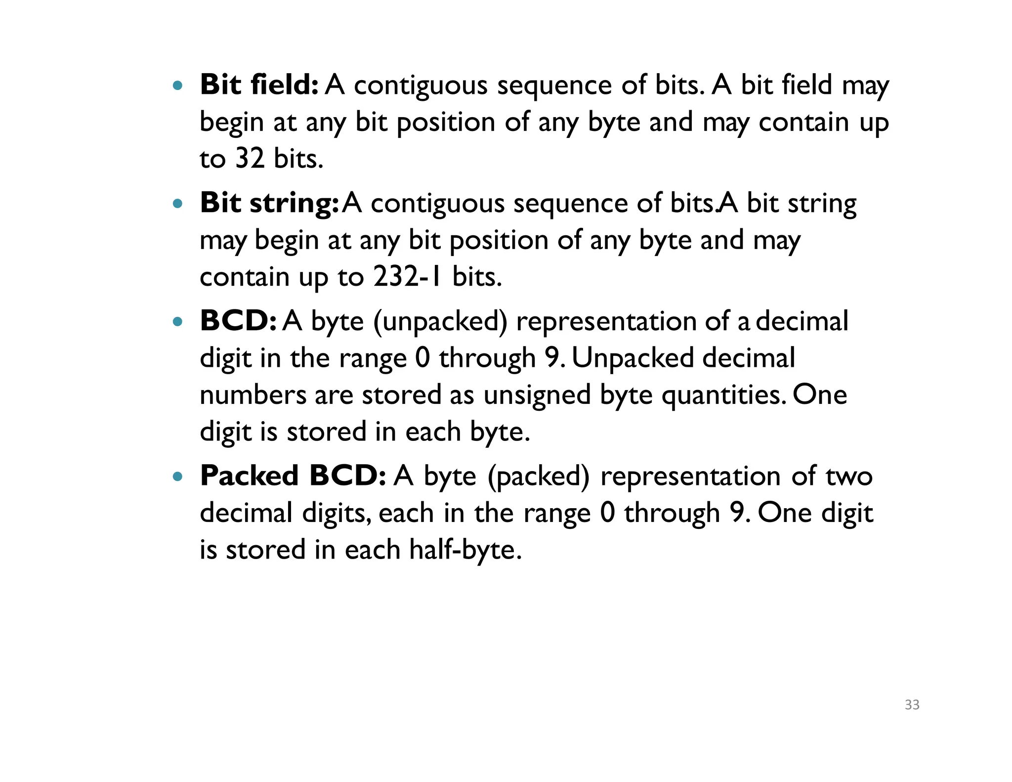
� Bit field:A contiguous sequence of bits. A bit field may
begin at any bit position of any byte and may contain up
to 32 bits.
� Bit string:A contiguous sequence of bits.A bit string
may begin at any bit position of any byte and may
contain up to 232-1 bits.
� BCD: A byte (unpacked) representation of adecimal
digit in the range 0 through 9. Unpacked decimal
numbers are stored as unsigned byte quantities. One
digit is stored in each byte.
� Packed BCD: A byte (packed) representation of two
decimal digits, each in the range 0 through 9. One digit
is stored in each half-byte.
33
Registers
35
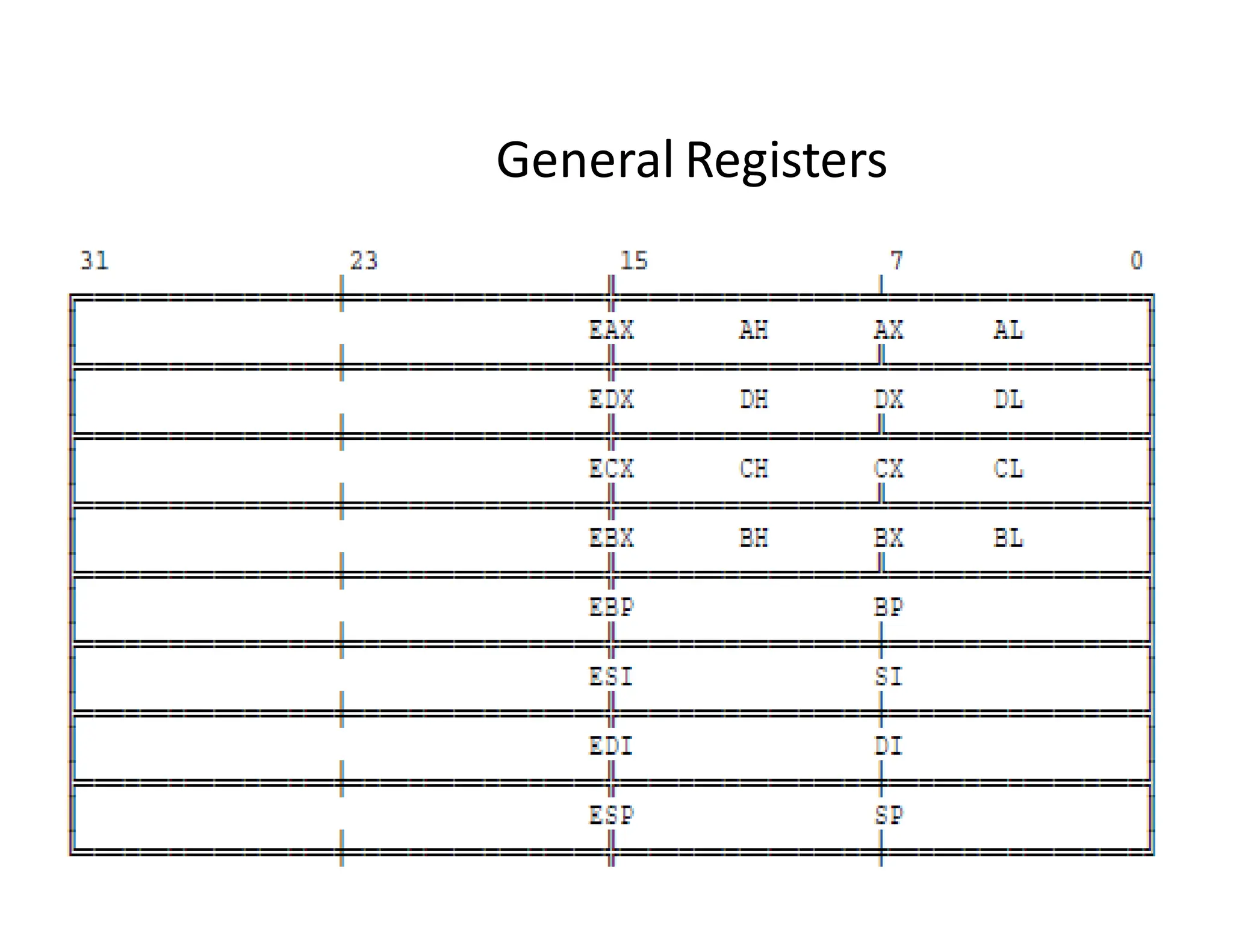
The 80386 haseight 32-bit general purpose registers
which may be used as either 8 bit, 16 bit or 32 bit
registers.
•A 32-bit register known as an extended register, is
represented by the register name with prefix E.
•Example : A 32 bit register correspondingto
AX is EAX
•So the general purpose registers of 386 are EAX,
EBX, ECX, EDX, EBP, ESP, ESI and
EDI
36.
Registers
36
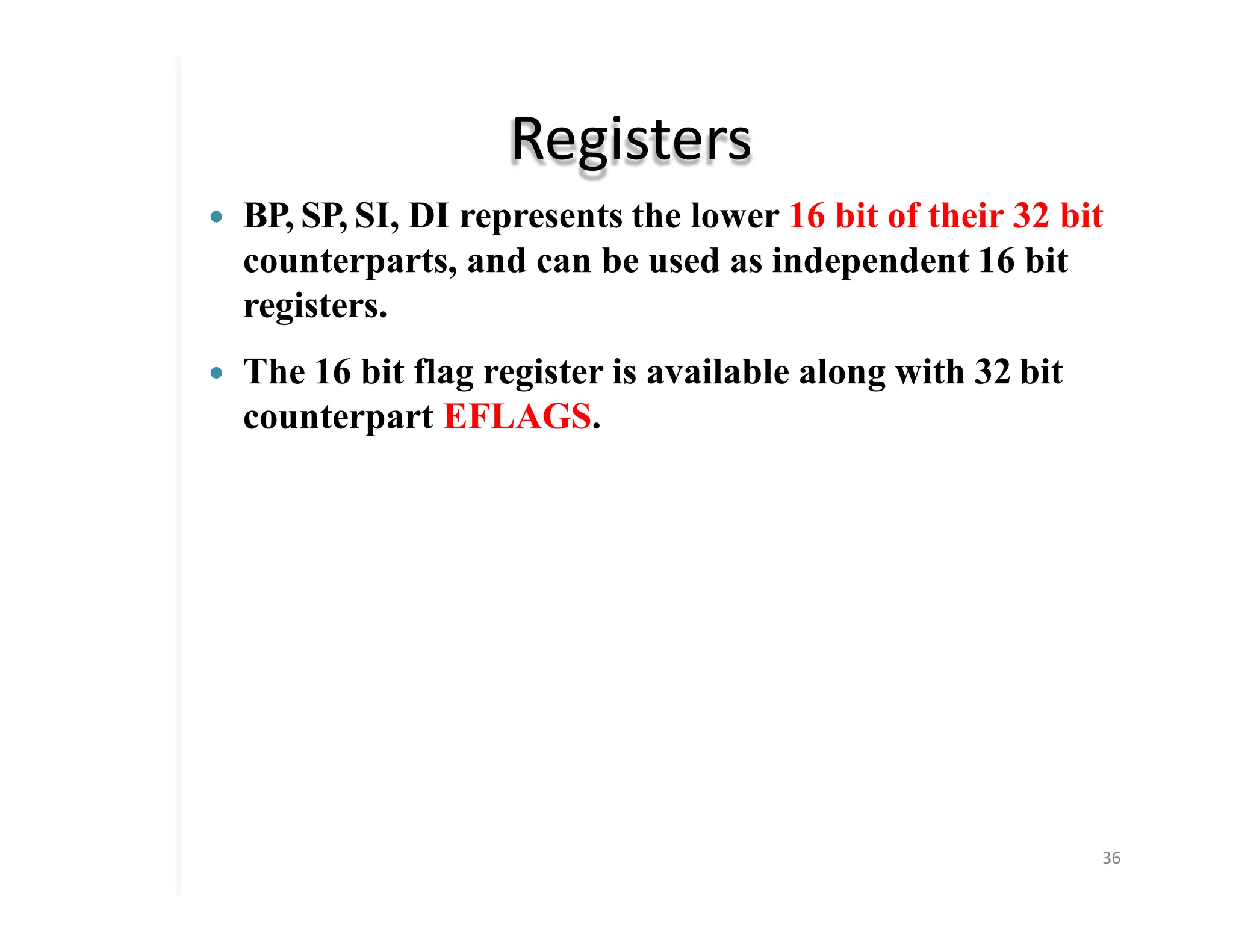
� BP, SP,SI, DI represents the lower 16 bit of their 32 bit
counterparts, and can be used as independent 16 bit
registers.
� The 16 bit flag register is available along with 32 bit
counterpart EFLAGS.
37.
Register Set
37
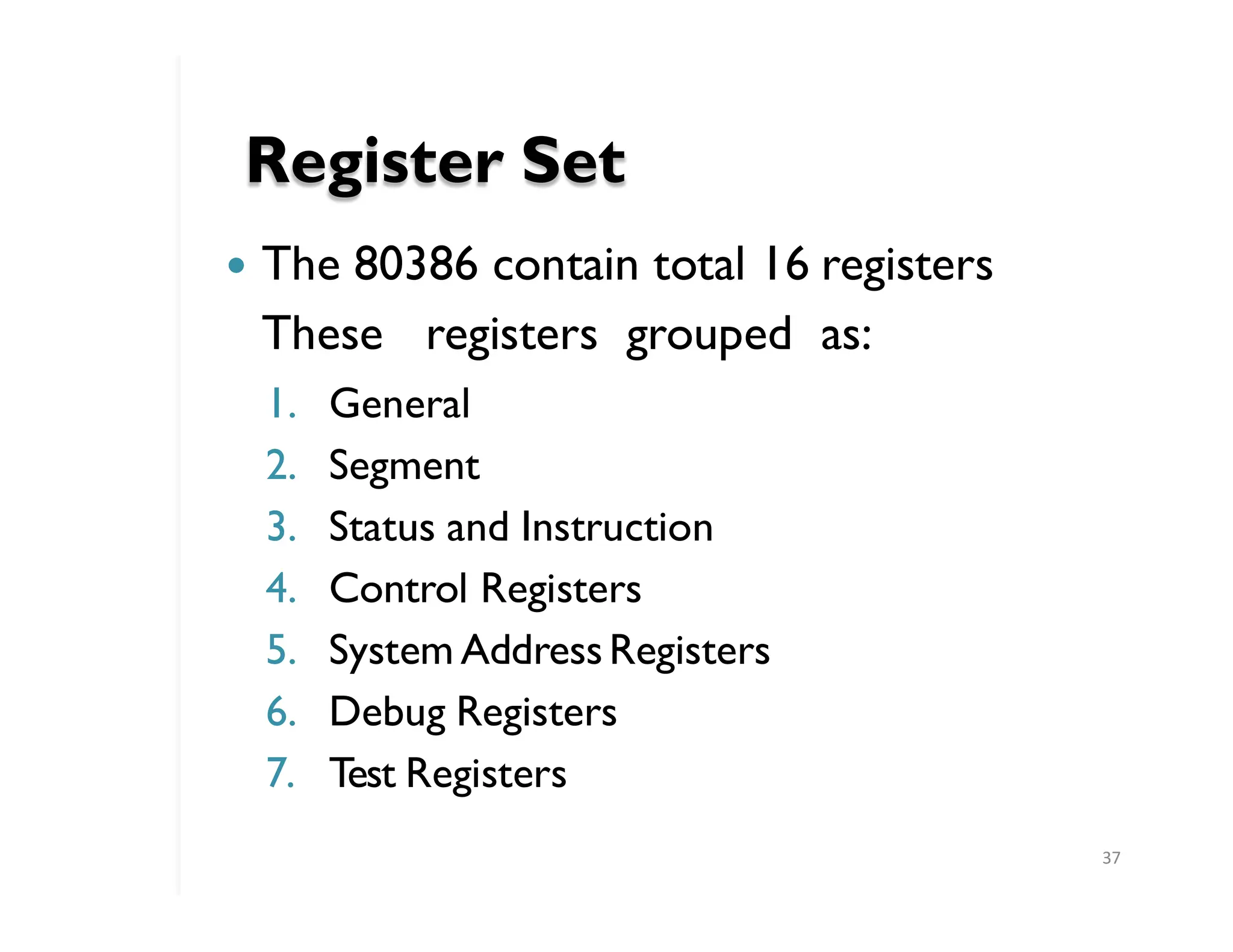
� The80386 contain total 16 registers
These registers grouped as:
1. General
2. Segment
3. Status and Instruction
4. Control Registers
5. System AddressRegisters
6. Debug Registers
7. Test Registers
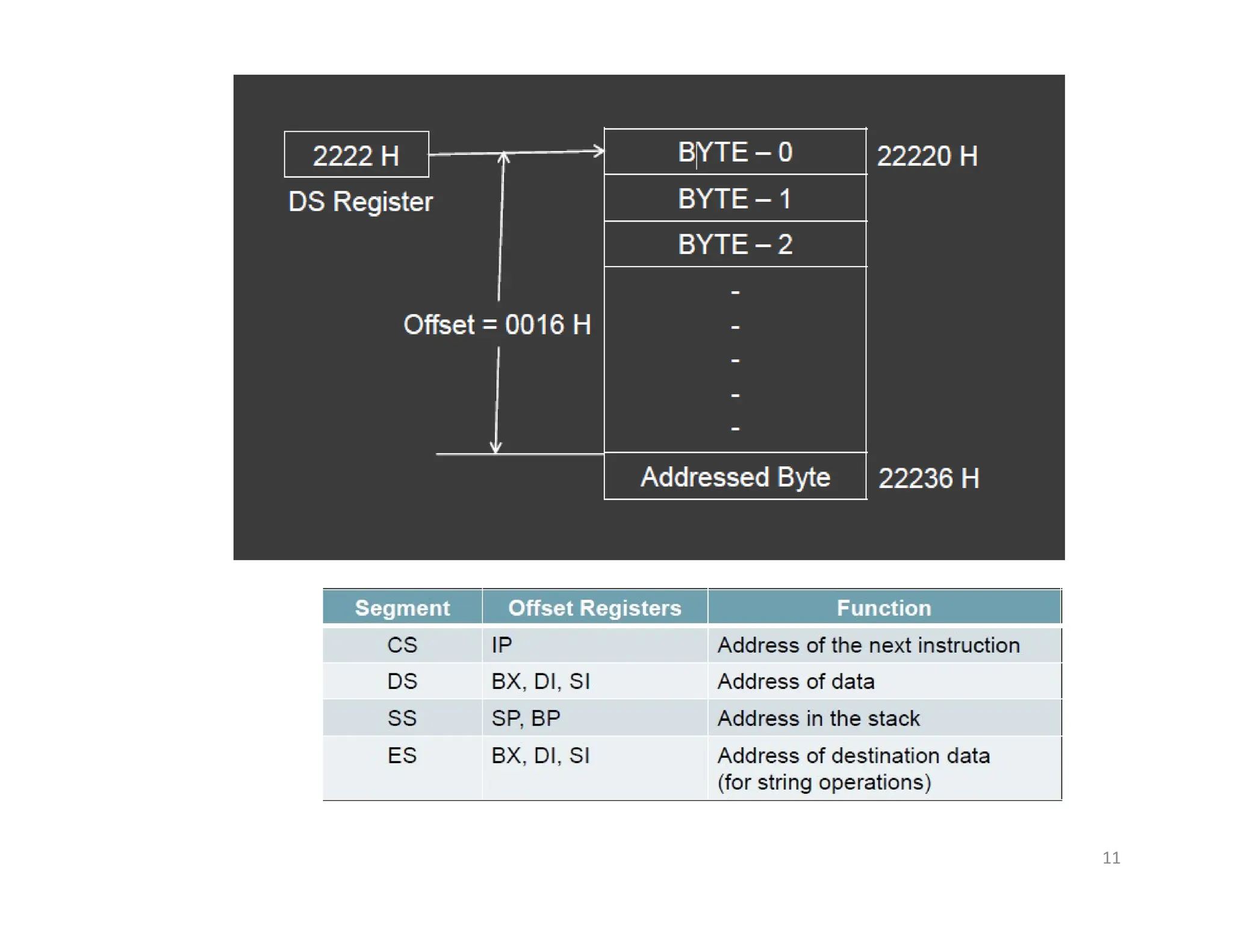
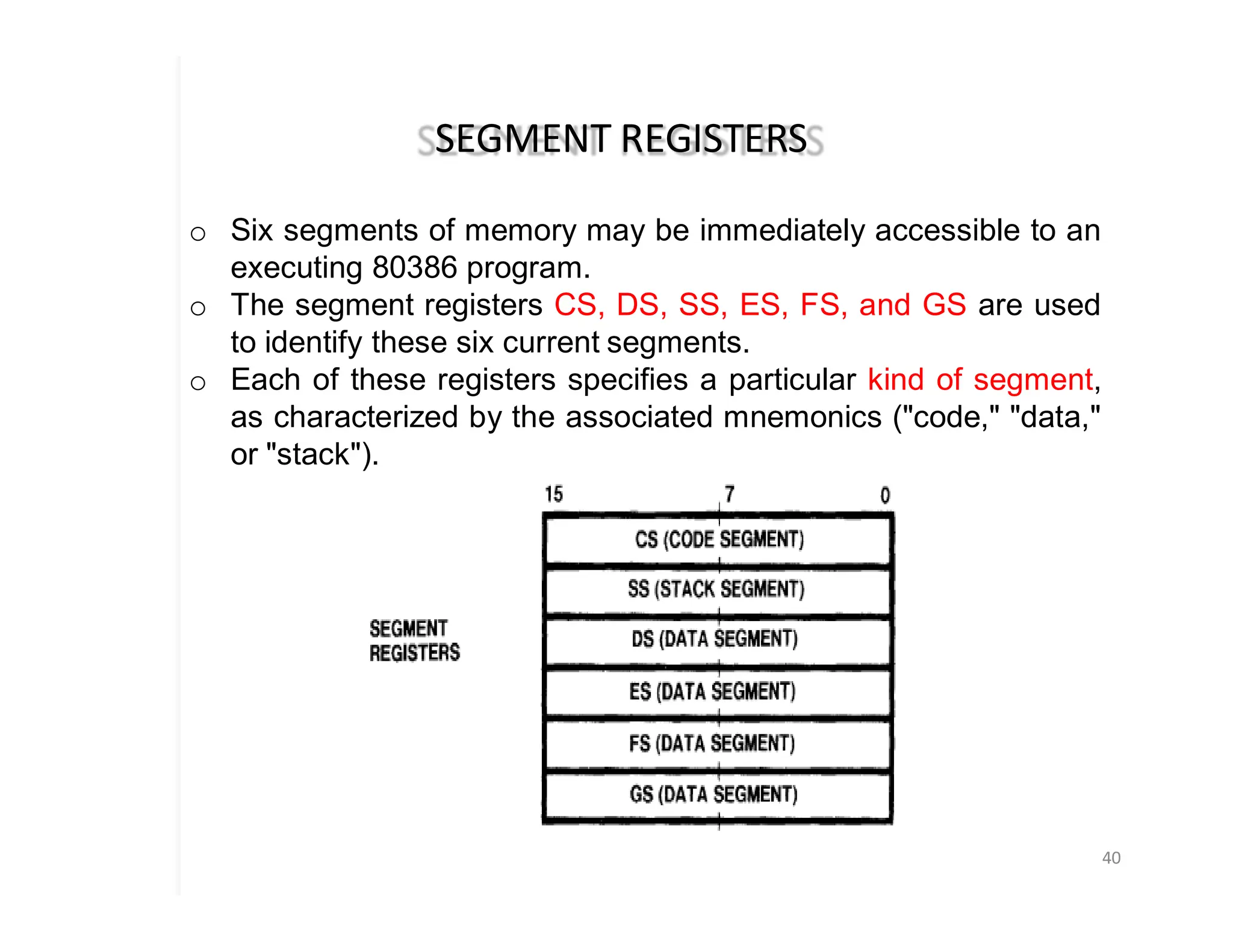
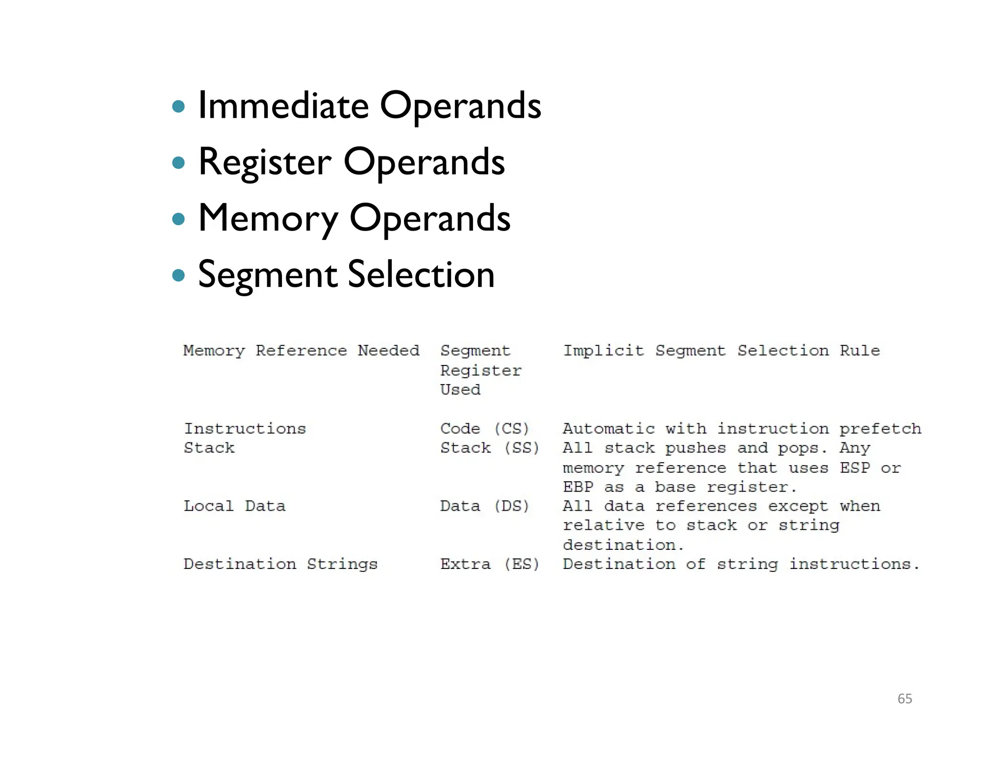
SEGMENT REGISTERS
40
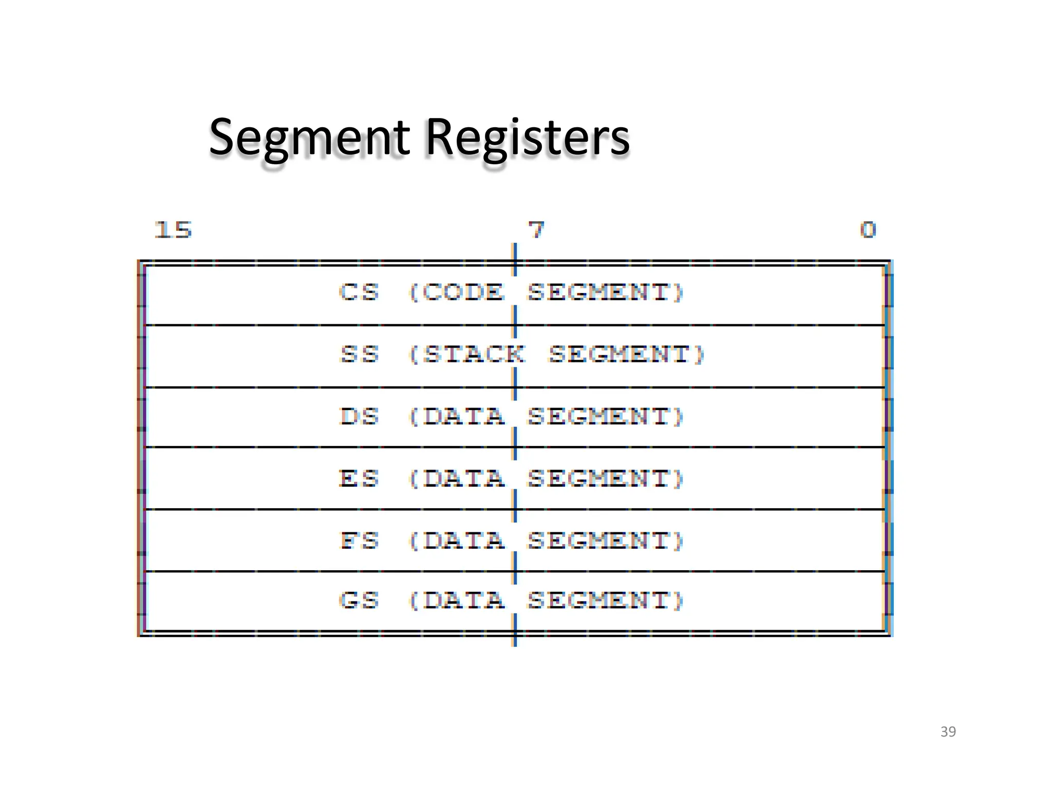
o Sixsegments of memory may be immediately accessible to an
executing 80386 program.
o The segment registers CS, DS, SS, ES, FS, and GS are used
to identify these six current segments.
o Each of these registers specifies a particular kind of segment,
as characterized by the associated mnemonics ("code," "data,"
or "stack").
41.
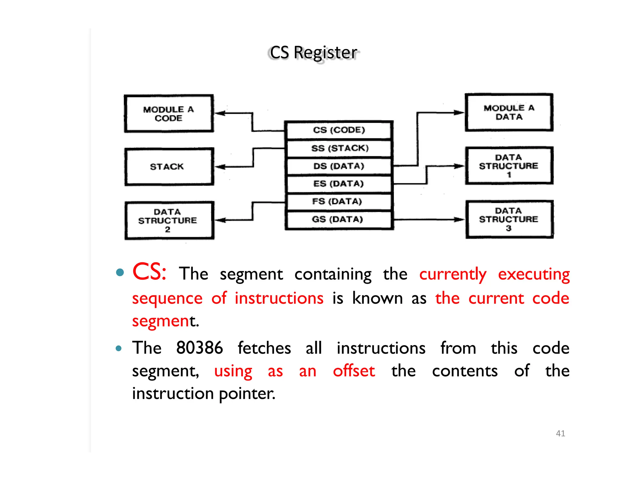
CS Register
41
� CS:The segment containing the currently executing
sequence of instructions is known as the current code
segment.
� The 80386 fetches all instructions from this code
segment, using as an offset the contents of the
instruction pointer.
42.
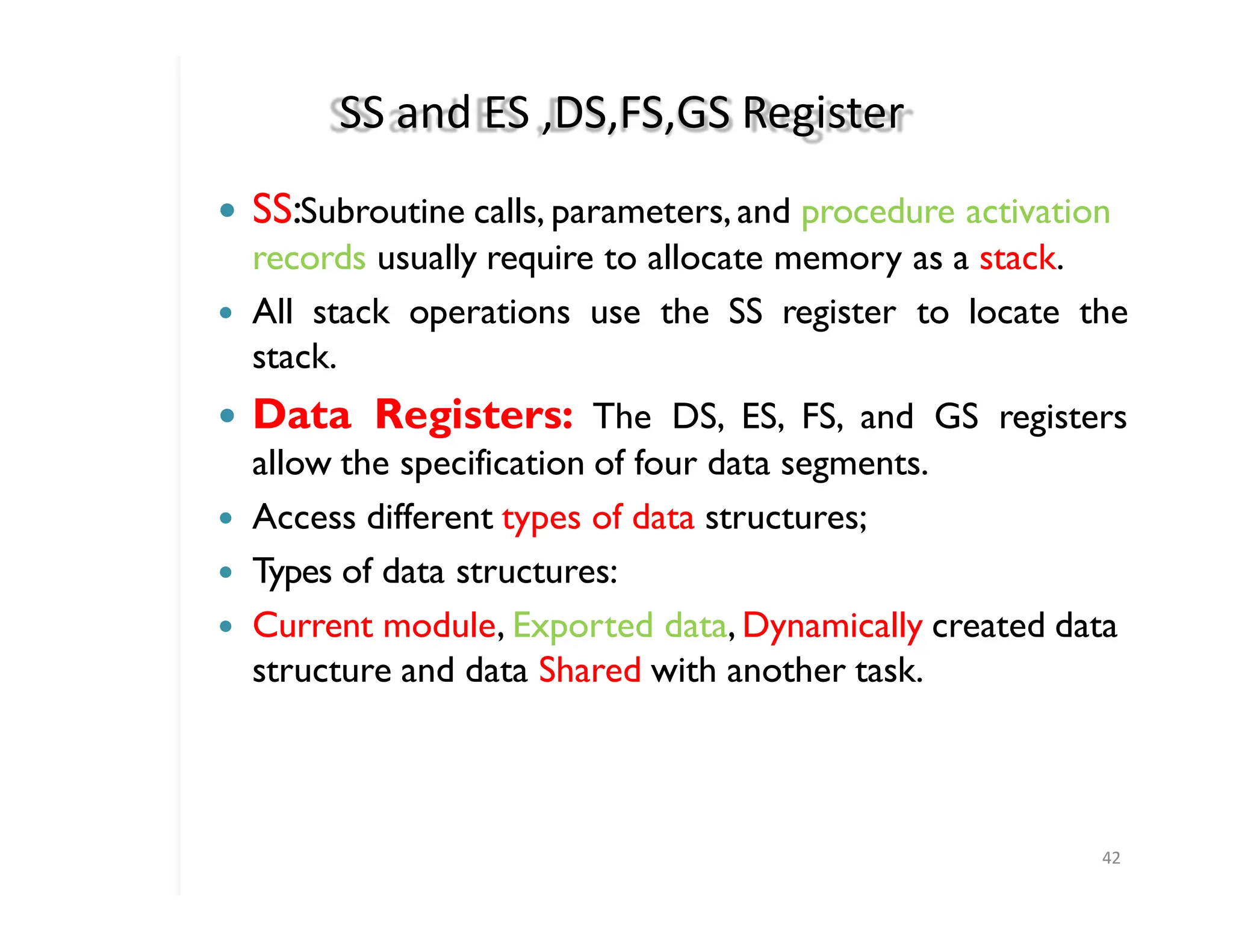
SS and ES,DS,FS,GS Register
42
� SS:Subroutine calls, parameters,and procedure activation
records usually require to allocate memory as a stack.
� All stack operations use the SS register to locate the
stack.
� Data Registers: The DS, ES, FS, and GS registers
allow the specification of four data segments.
� Access different types of data structures;
� Types of data structures:
� Current module, Exported data, Dynamically created data
structure and data Shared with another task.
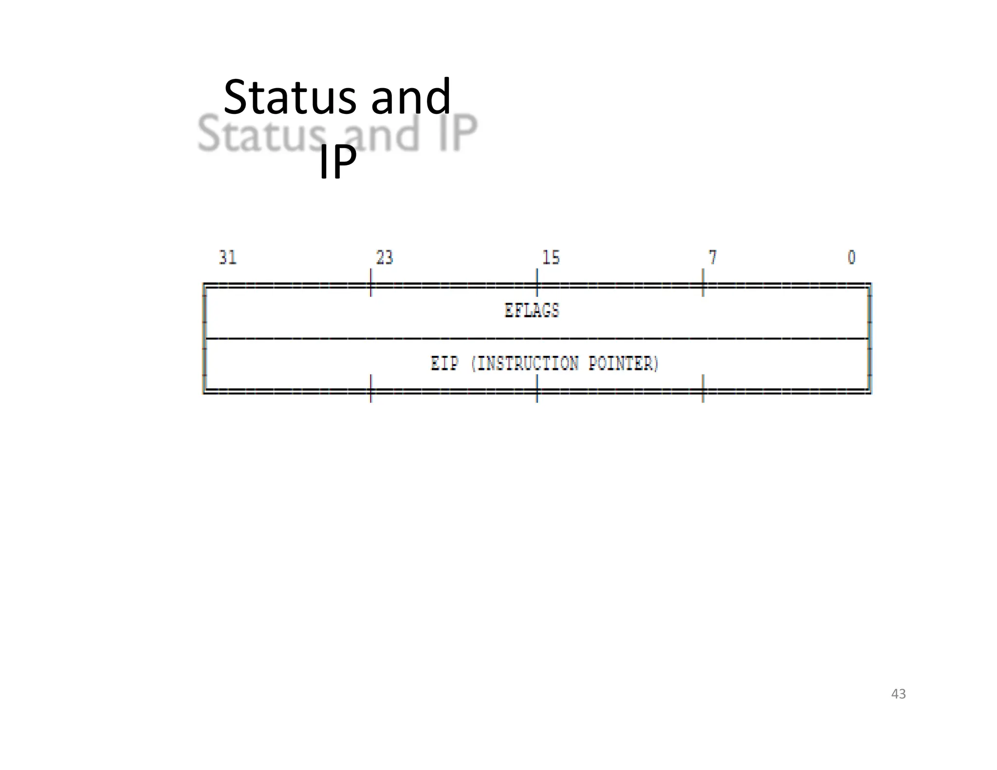
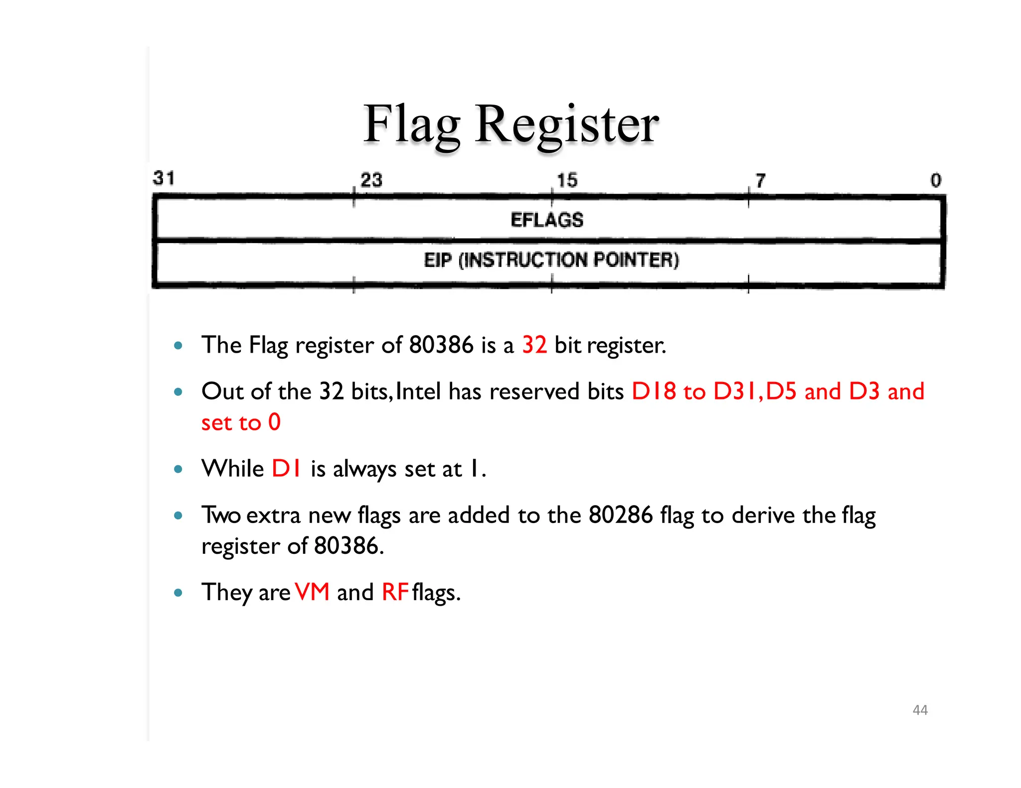
Flag Register
44
� TheFlag register of 80386 is a 32 bit register.
� Out of the 32 bits,Intel has reserved bits D18 to D31,D5 and D3 and
set to 0
� While D1 is always set at 1.
� T
wo extra new flags are added to the 80286 flag to derive the flag
register of 80386.
� They areVM and RFflags.
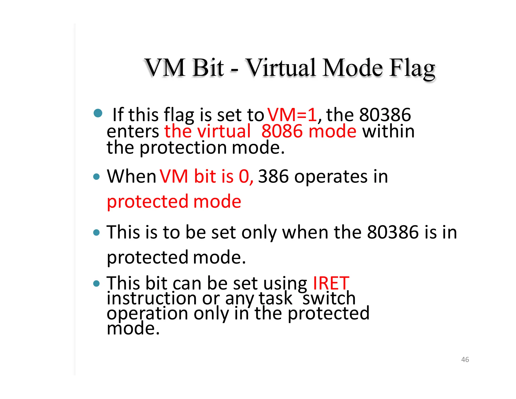
VM Bit -Virtual Mode Flag
� If this flag is set toVM=1, the 80386
enters the virtual 8086 mode within
the protection mode.
� WhenVM bit is 0, 386 operates in
protected mode
� This is to be set only when the 80386 is in
protected mode.
� This bit can be set using IRET
instruction or any task switch
operation only in the protected
mode.
46
47.
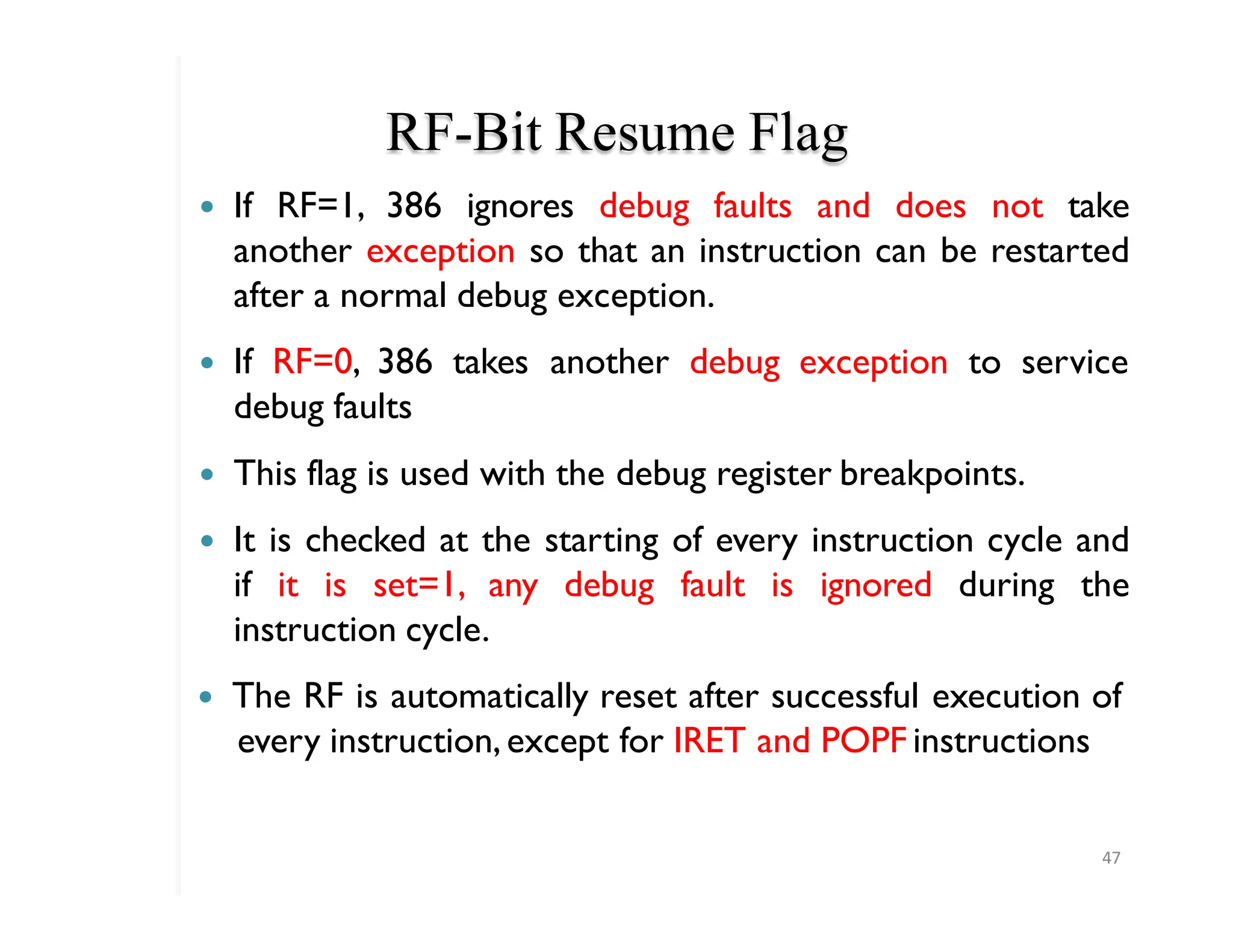
RF-Bit Resume Flag
47
�If RF=1, 386 ignores debug faults and does not take
another exception so that an instruction can be restarted
after a normal debug exception.
� If RF=0, 386 takes another debug exception to service
debug faults
� This flag is used with the debug register breakpoints.
� It is checked at the starting of every instruction cycle and
if it is set=1, any debug fault is ignored during the
instruction cycle.
� The RF is automatically reset after successful execution of
every instruction,except for IRET and POPF instructions
48.
RF- Resume Flag...
48
�Also, it is not automatically cleared after the successful
execution of JMP, CALL and INT instruction causing a task
switch.
49.
� VM (Virtual8086 Mode): If set while the
Intel386 DX is in Protected Mode, the
Intel386 DX will switch to Virtual 8086
operation.
� The VM bit can be set only in Protected
Mode, by the IRET instruction (if current
privilege level e 0)
� RF (Resume Flag): The RF flag is used in
conjunction with the debug register
breakpoints.
� When RF is set, it causes any debug fault to
be ignored on the next instruction.
49
50.
� NT (NestedTask): This flag applies to
Protected Mode.
� NT is set to indicate that the execution of
this task is nested within another task
� The value of NT in EFLAGS is tested by
the IRET instruction to determine
whether to do an inter-task return or an
intra-task return.
50
51.
IOPL (Input /Output Privilege
Level)
51
� This two-bit field applies to Protected Mode.
IOPL indicates the numerically maximum
CPL(current privilege level) value permitted
to execute I/O instructions without
generating an Exception
� It also indicates the maximum CPL value
allowing alteration of the IF (INTR Enable
Flag) bit when new values are popped into the
EFLAG register
52.
� IF (INTREnable Flag): The IF flag, when set,
allows recognition of external interrupts
signaled on the INTR pin.
� TF (Trap Enable Flag): When TF is set, the
Intel386 DX generates an exception 1 trap
after the next instruction is executed.
� When TF is reset, exception 1 traps occur
only as a function of the breakpoint
addresses loaded into debug registers
DR0-DR3.
52
53.
� OF (Overflow
53
Flag): It is set if the
operation resulted in a signed overflow.
Signed overflow occurs when the operation
resulted in carry/borrow into the sign bit
(high-order bit) of the result.
� DF (Direction Flag) : DF defines whether
ESI and/or EDI registers post-decrement or
post-increment during the string
instructions.
� Post-decrement occurs if DF is set
54.
Flag
s
54
� The arithmeticinstructions use CF, SF, ZF, AF,
PF,CF
� The control flag DF controls “STRING”
instruction
� Clearing DF flag causes string instructions
to auto increment or to process string
from low to high address
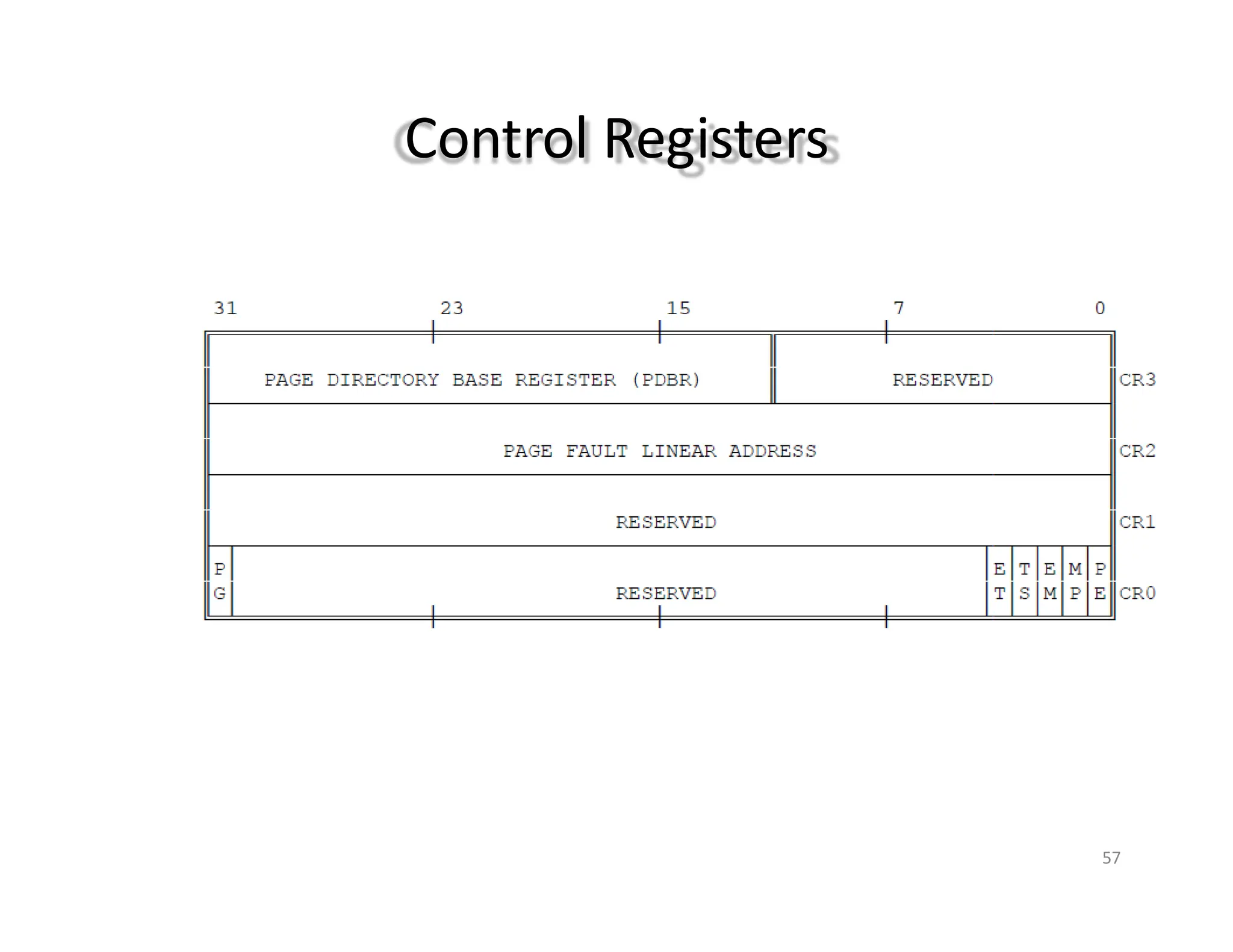
Control Registers
56
� The80386 has four 32 bit control registers CR0,
CR1, CR2 and CR3 to hold global machine status.
� CR1 is not used in 386 and reserved for future use.
� Load and store instructions are available to access
these registers.
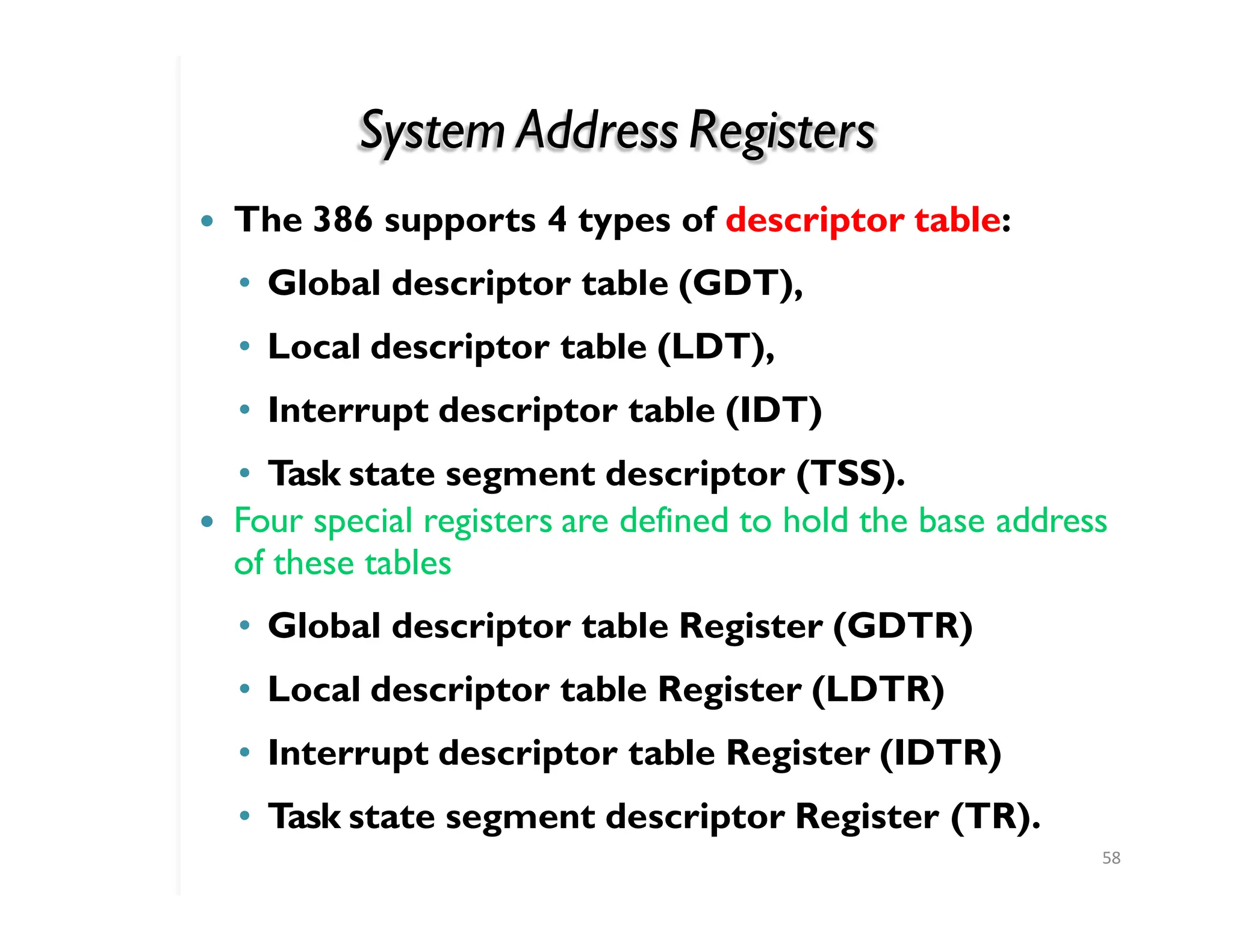
System Address Registers
58
�The 386 supports 4 types of descriptor table:
• Global descriptor table (GDT),
• Local descriptor table (LDT),
• Interrupt descriptor table (IDT)
• Task state segment descriptor (TSS).
� Four special registers are defined to hold the base address
of these tables
• Global descriptor table Register (GDTR)
• Local descriptor table Register (LDTR)
• Interrupt descriptor table Register (IDTR)
• Task state segment descriptor Register (TR).
59.
Debug Registers
59
� Intelhas provided a set of 8 debug registers for
hardware debugging.
� DR4 and DR5 are Intel reserved.
� The initial four registers DR0 to DR3 store four
program controllable breakpoint addresses,
� DR6 and DR7 respectively hold breakpoint status
and breakpoint control information.
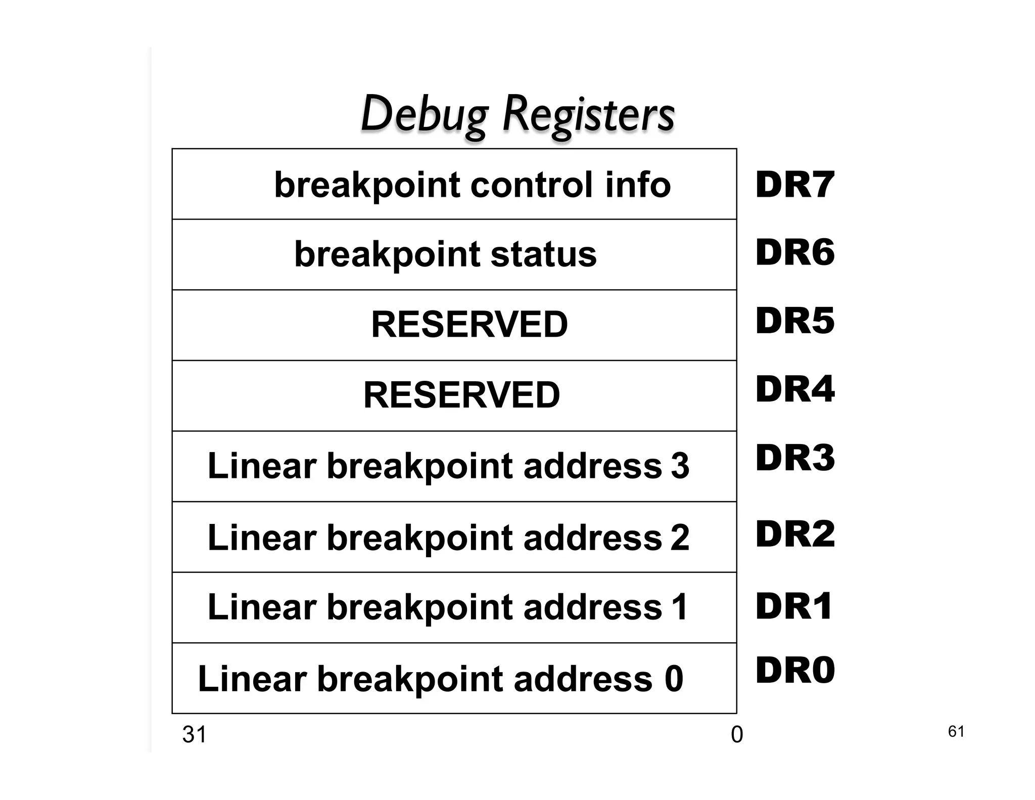
60.
Debug Registers
61
breakpoint controlinfo
breakpoint status
RESERVED
RESERVED
Linear breakpoint address 3
Linear breakpoint address 2
Linear breakpoint address 1
Linear breakpoint address 0
DR7
DR6
DR5
DR4
DR3
DR2
DR1
DR0
31 0
61.
Test Registers
61
� T
wotest register are provided by
80386 for page caching namely test
control and test status register.
62.
INSTRUCTION FORMAT
62
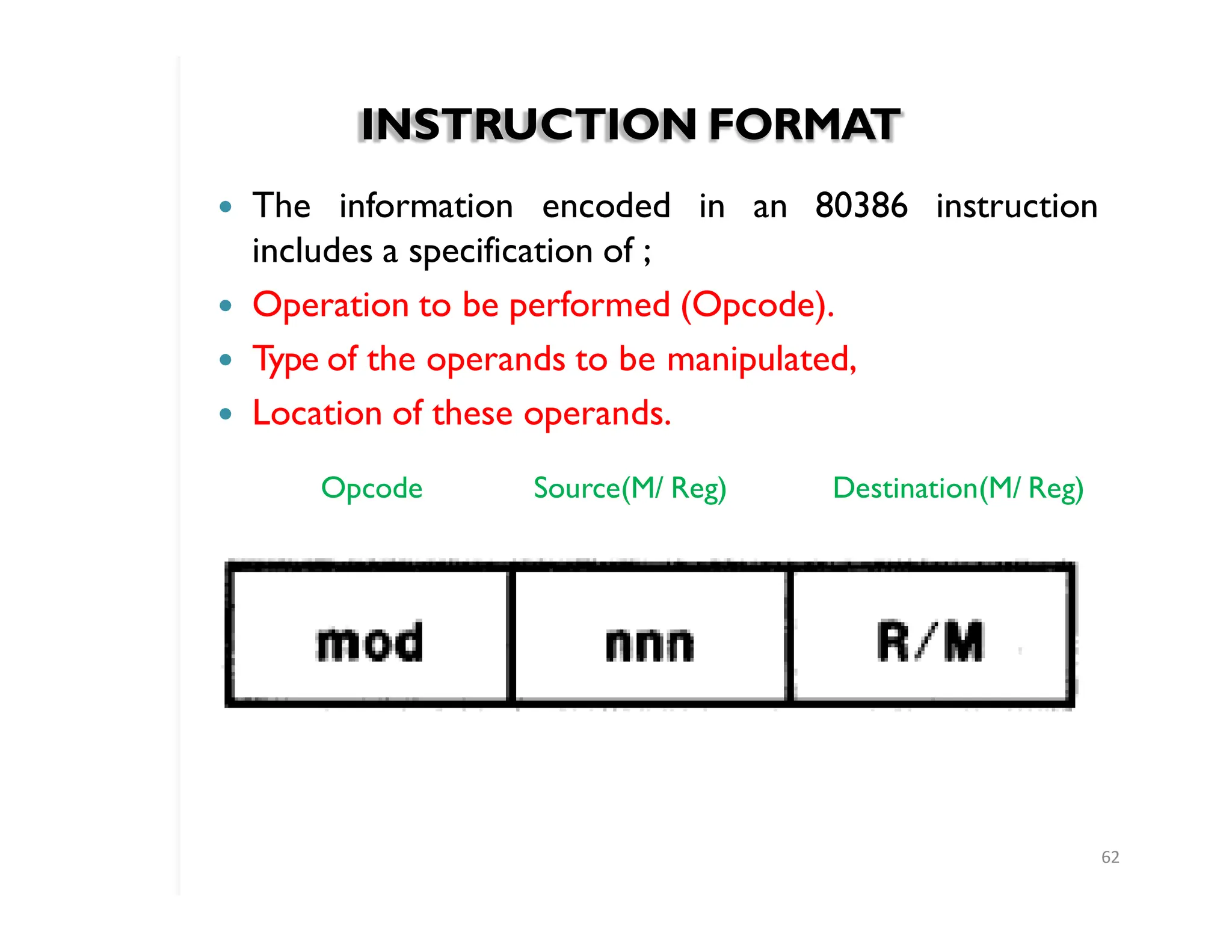
� Theinformation encoded in an 80386 instruction
includes a specification of ;
� Operation to be performed (Opcode).
� Type of the operands to be manipulated,
� Location of these operands.
Opcode Source(M/ Reg) Destination(M/ Reg)
63.
Operand Selection
63
� Inthe instruction itself(immediate operand)
� In a register
� In memory
� At an I/O port
� Implicit operand
� Explicit operand
� Implicit and Explicit Operand
64.
INSTRUCTION FORMAT
64
� T
wo-operandinstructions of the 80386 permit
operations of the following kinds:
� • Register-to-register
� • Register-to-memory
� • Memory-to-register
� • Immediate-to-register
� • Immediate-to-memory
� Certain string instructions and stack manipulation
instructions transfer data from memory to memory.
� Push and pop stack operations allow transfer between
memory operands and the memory-based stack.
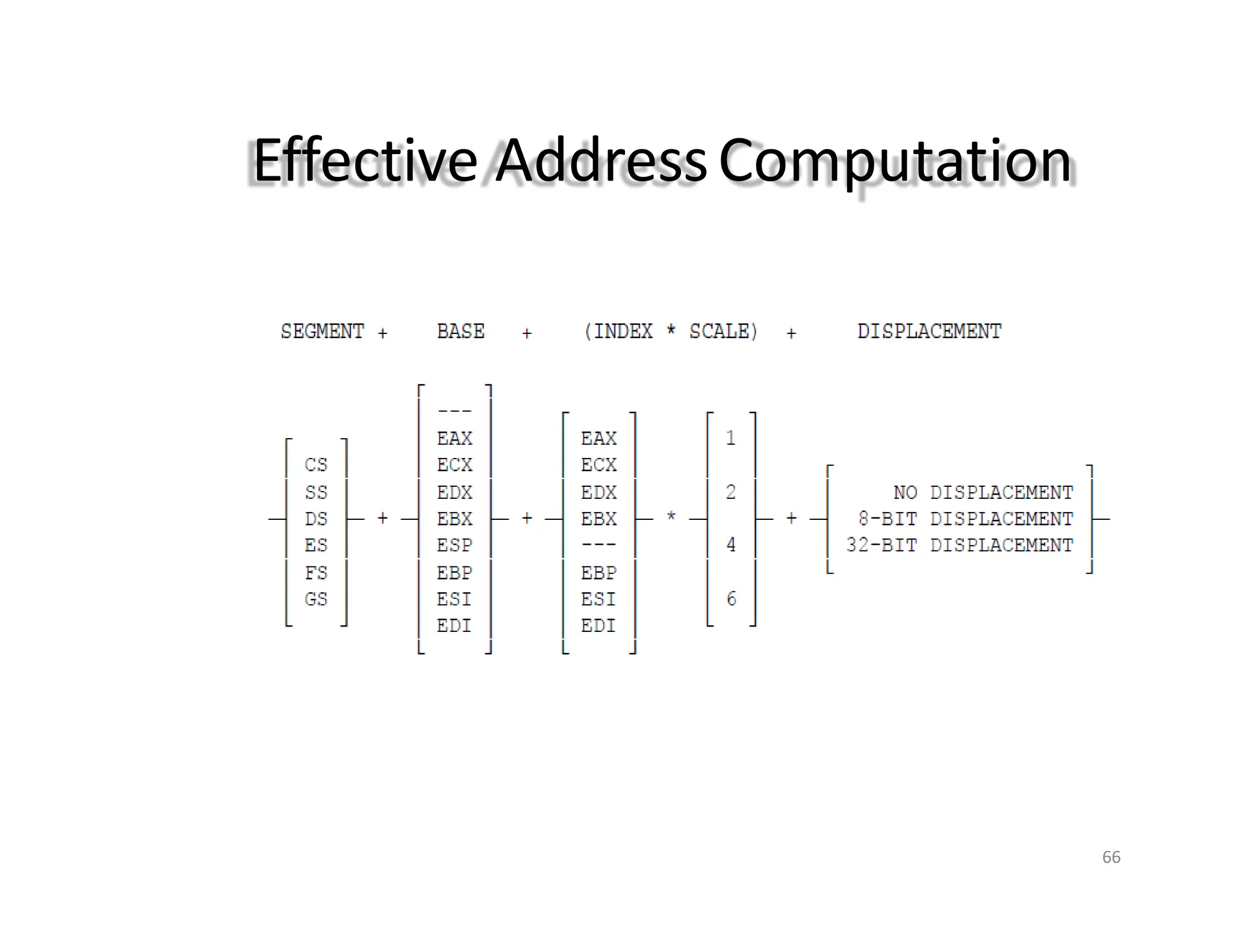
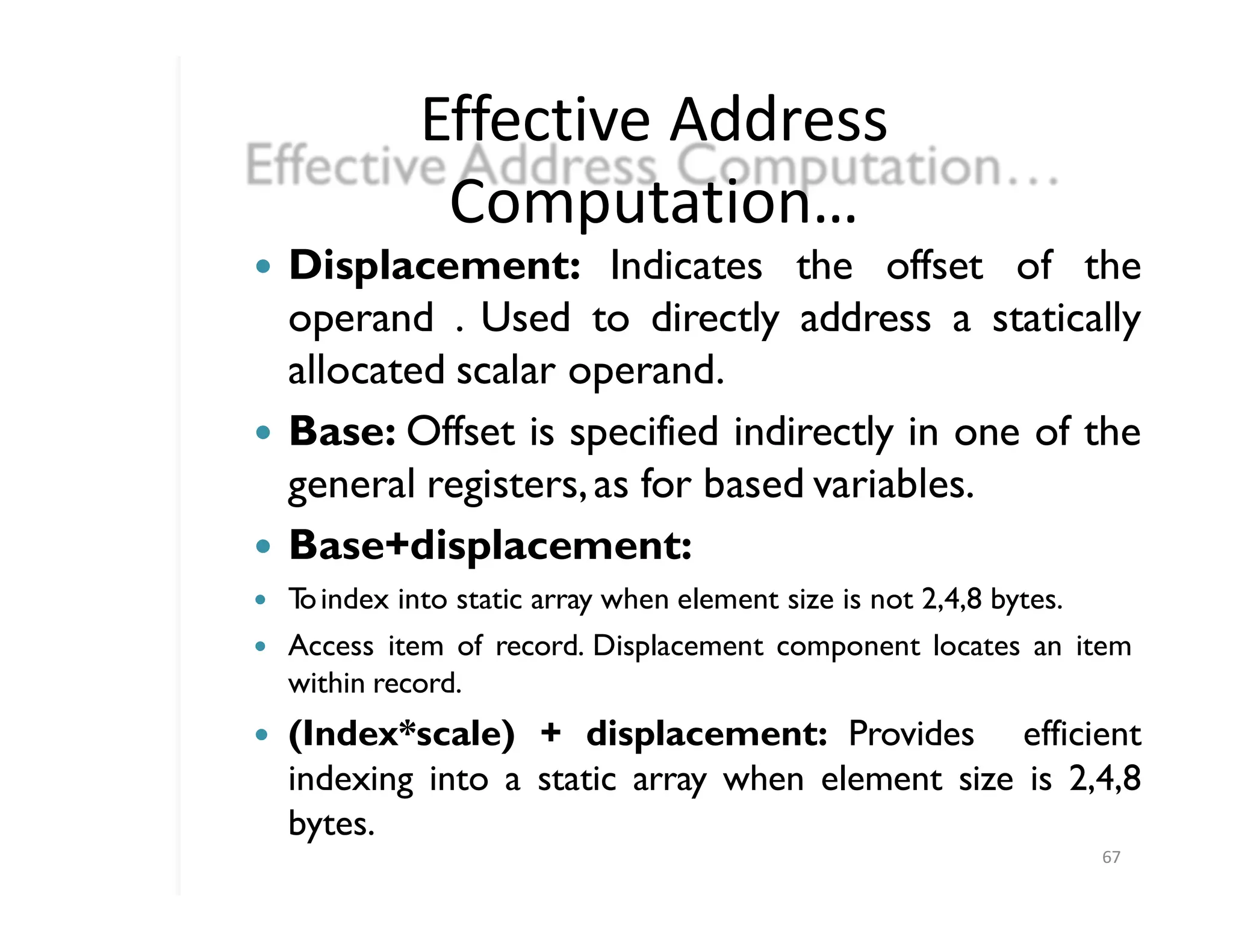
Effective Address
Computation…
67
� Displacement:Indicates the offset of the
operand . Used to directly address a statically
allocated scalar operand.
� Base: Offset is specified indirectly in one of the
general registers,as for based variables.
� Base+displacement:
� T
oindex into static array when element size is not 2,4,8 bytes.
� Access item of record. Displacement component locates an item
within record.
� (Index*scale) + displacement: Provides efficient
indexing into a static array when element size is 2,4,8
bytes.
68.
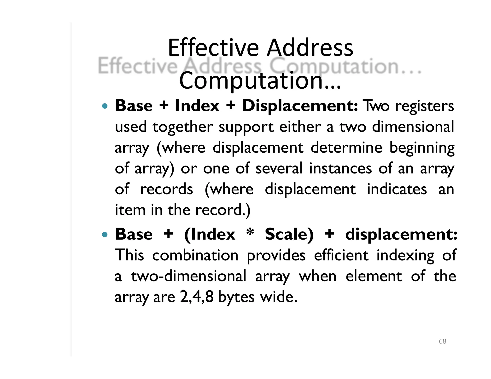
Effective Address
Computation…
68
� Base+ Index + Displacement: T
wo registers
used together support either a two dimensional
array (where displacement determine beginning
of array) or one of several instances of an array
of records (where displacement indicates an
item in the record.)
� Base + (Index * Scale) + displacement:
This combination provides efficient indexing of
a two-dimensional array when element of the
array are 2,4,8 bytes wide.
69.
Interrupts and Exceptions
69
program
�T
wo mechanism for interrupting
execution
� Exceptions are synchronous events that are
the responses of the CPU to certain conditions
detected during the execution of an instruction.
� Interrupts are asynchronous events typically
triggered by external devices needing attention.
APPLICATIONS INSTRUCTION SET
�T
o write application software for the 80386
executing in protected virtual-address
mode.
� DA
TAMOVEMENT INSTRUCTIONS
� They fall into the following classes:
� 1. General-purpose data movement
instructions.
� 2. Stack manipulationinstructions.
� 3.Type-conversion instructions.
71
72.
General-Purpose Data Movement
Instructions
72
�MOV (Move) transfers a byte, word, or double word from
the source operand to the destination operand.
� The MOV instruction is useful for transferring data along
any of these paths
� •T
oa register from memory
� •T
omemory from a register
� • Between general registers
� • Immediate data to a register
� • Immediate data to a memory
� XCHG (Exchange) swaps the contents of two operands.
73.
Stack Manipulation
Instructions
73
� PUSH(Push) decrements the stack pointer (ESP), then
transfers the source operand to the top of stack indicated
by ESP
� PUSH is often used to place parameters on the stack
before calling a procedure.
� The PUSH instruction operates on memory operands,
immediate operands, and register.
� PUSHA (Push All Registers) saves the contents of the
eight general registers on the stack..
� The processor pushes the general registers on the stack
in the following order:
� EAX, ECX, EDX, EBX, the initial value of ESP before EAX
was pushed,EBP,ESI,and EDI.
74.
Type Conversion
Instructions
74
� Thetype conversion instructions convert bytes into words,
words into double words, and double words into 64-bit
items (quad-words).
� CWD,CDQ,CBW,and CWDE
� CWD (ConvertWord to Doubleword)
� CBW (Convert Byte toWord)
� CDQ (Convert Doubleword to Quad-Word)
� CWDE (ConvertWord to Doubleword Extended)
� MOVSX (Move with Sign Extension)
� MOVZX (Move with Zero Extension)
75.
BINARY ARITHMETICINSTRUCTIONS
** Additionand SubtractionInstructions
75
� ADD D ,S (sets CF is there is carry)
� ADC D ,S (D= D+S+C)
� INC D (Increment Byte,Word or Doubleword by 1)
� SUB D ,S (sets CF is there is borrow)
� SBB D ,S (D= D-S-C)
� DEC D (Decrement Byte,Word or Doubleword by 1)
76.
BINARY ARITHMETIC INSTRUCTIONS
**Comparison and Sign Change Instructions
76
� CMP D,S (Destination-Source)
Updates OF,SF,ZF,AF,PF and CF
� NEG D
Subtracts a signed integer operand from zero
77.
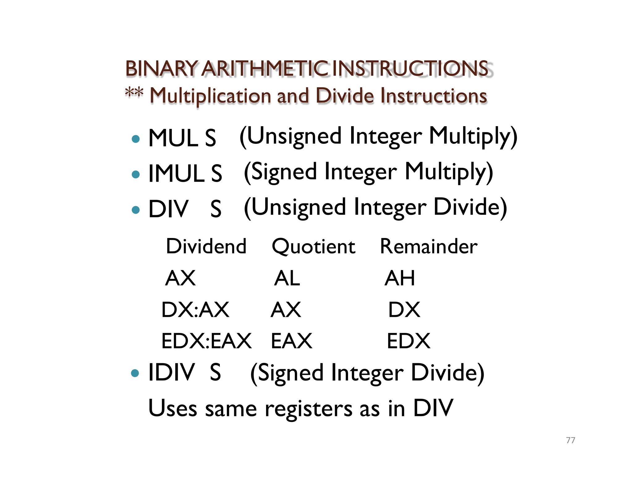
BINARYARITHMETICINSTRUCTIONS
** Multiplication andDivide Instructions
77
� MUL S
� IMUL S
� DIV S
(Unsigned Integer Multiply)
(Signed Integer Multiply)
(Unsigned Integer Divide)
Dividend Quotient Remainder
AX AL AH
DX:AX AX DX
EDX:EAX EAX EDX
� IDIV S (Signed Integer Divide)
Uses same registers as in DIV
78.
DECIMAL ARITHMETIC INSTRUCTIONS
78
�Decimal Arithmetic is performed by combining the binary
arithmetic instructions with decimal arithmetic
instructions.
� Decimal Arithmetic instructions are used in one of the
following ways
- T
o adjust the results of a previous binary arithmetic
operation to produce a valid packed or unpacked decimal
result.
- T
o adjust the inputs to a subsequent binary arithmetic
operation so that the operation will produce a valid
packed or unpacked decimal result.
� These instructions operate only on the AL or AH registers.
Most utilize the AF flag.
79.
DECIMAL ARITHMETIC INSTRUCTIONS
**Packed BCD AdjustmentInstructions
79
� DAA (Decimal Adjust afterAddition)
- Adjusts the result of adding two valid packed decimal
operands inAL.
output
- DAA instruction gives us correct decimal
instead of hexadecimal.
- Carry flag is set if carry was needed.
� DAS (Decimal Adjust after Subtraction)
- Adjusts the result of Subtracting two valid packed
decimal operands inAL.
- DAS instruction gives us correct decimal output instead
of hexadecimal.
- Carry flag is set if borrow was needed.
80.
DECIMAL ARITHMETIC INSTRUCTIONS
**Unpacked BCD AdjustmentInstructions
80
� AAA (AsciiAdjustAfterAddition)
- AL contain valid unpacked decimal number andAH=00
- AAA must always follow addition of two unpacked
decimal operands inAL.
- Carry flag is set and AH is incremented if a carry is
necessary.
� AAS (Ascii AdjustAfter Subtraction)
- AL contain valid unpacked decimal number andAH=00
- AAS must always follow Subtraction of one unpacked
decimal operands from another inAL.
- Carry flag is set and AH is incremented if a borrow is
necessary.
81.
DECIMAL ARITHMETIC INSTRUCTIONS
**Unpacked BCD AdjustmentInstructions
81
� AAM (Ascii Adjust AfterMultiplication)
- Corrects multiplication of two unpacked decimal number.
- The high order digit is left inAH,the low order digit inAL.
� AAD (Ascii AdjustAfter Division)
- Modifies numerator in AH and AL for unpacked decimal
operands divide operation.
- Quotient produced will be valid unpacked decimal.
- The high order digit is left inAH,the low order digit inAL.
- Adjusts the result in AL and makeAH=00
82.
LOGICAL INSTRUCTIONS
82
� Thegroup of logical instructions includes:
• The Boolean operation instructions
• Bit test and modify instructions
• Bit scan instructions
• Rotate and shift instructions
• Byte set on condition
83.
The Boolean operation
instructions
83
�NOT (Not)
Inverts the bits in the specified operand to form a one‟s
complement of the operand. Has no effect on flags.
� AND,OR, andXOR
AND- is useful instruction for turning a particular bit off.
(Turn to 0)
OR- is useful instruction for setting a particular bit on.(Turn
to 1)
XOR- is useful instruction for clearing a register.Oruseful
for toggling particular bit without changing other bits.
84.
Bit test andmodify instructions
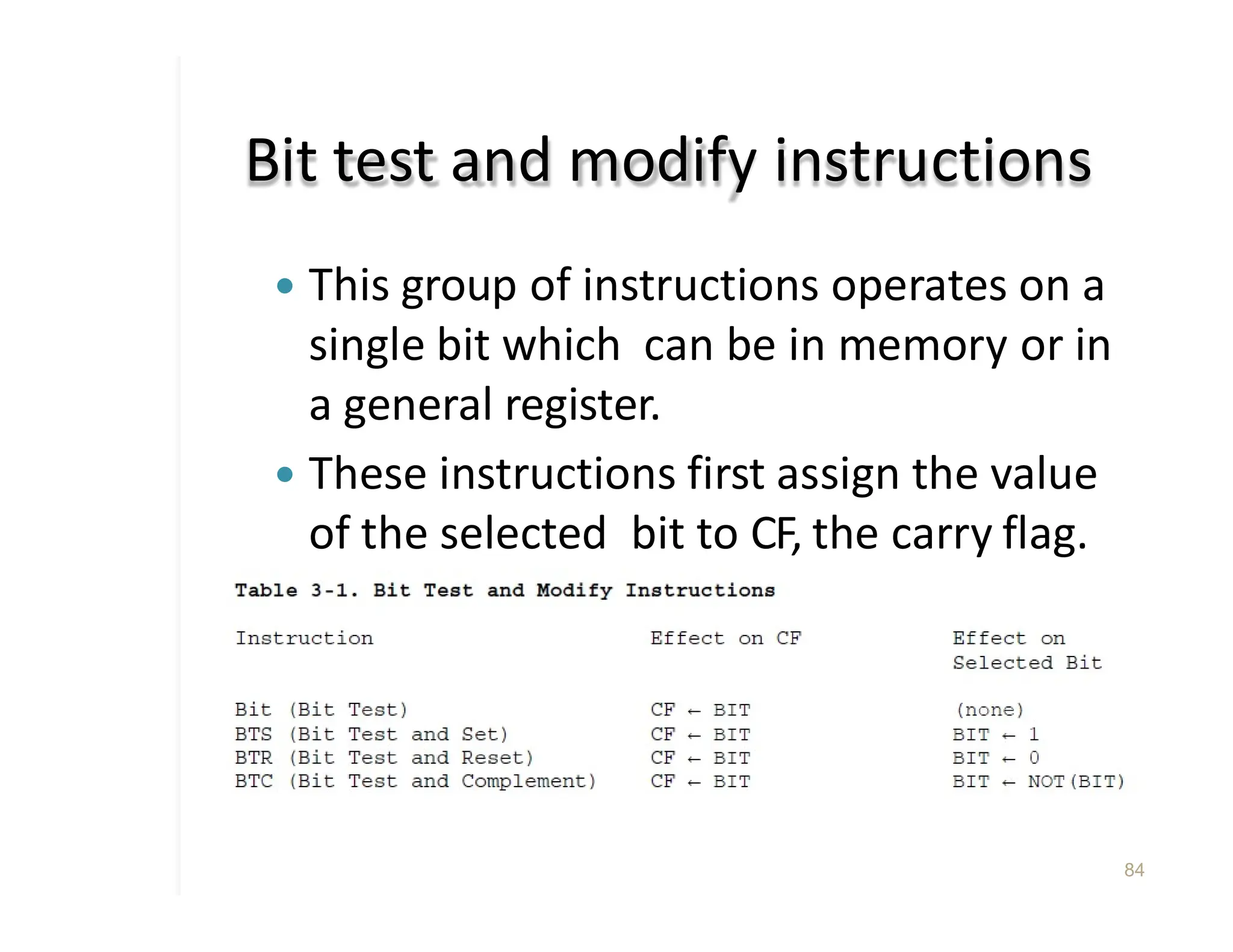
� This group of instructions operates on a
single bit which can be in memory or in
a general register.
� These instructions first assign the value
of the selected bit to CF, the carry flag.
� Then a new value is assigned to
the selected bit, as determined by
the operation.
84
85.
Bit scan instructions
85
�These instructions scan a word or doubleword for
a one-bit and store the index of the first set bit
into a register.
� The bit string being scanned may be either in a
register or in memory.
� Affects ZF=1 if word is zero,otherwise clear ZF
� BSF (Bit Scan Forward) scans from low-order
to high-order (starting from bit index zero).
� BSR (Bit Scan Reverse) scans from high-order
to low-order (starting from bit index 15 of a word
or index 31 of a doubleword).
86.
Shift and RotateInstructions
86
� These instructions fall into the following
classes:
• Shift instructions
• Double shift instructions
• Rotate instructions
87.
SHIFT INSTRUCTIONS
87
� Thebits in bytes,words, and double words may be shifted
arithmetically or logically.
� CF always contains the value of the last bit shifted out of
the destination operand.
� OF is set if the value of the high-order (sign) bit was
changed by the operation.
� SAL (Shift ArithmeticLeft)
� SHL (Shift Logical Left)
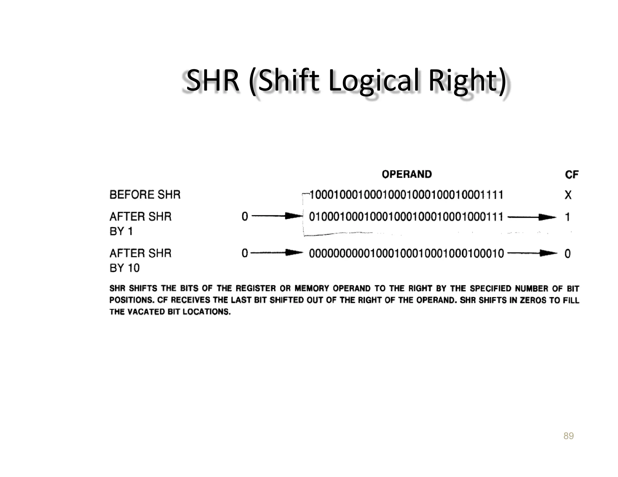
� SHR (Shift Logical Right)
� SAR (Shift ArithmeticRight)
� ROL (Rotate Left)
� ROR (Rotate Right)
� RCL (RotateThrough CarryLeft)
88.
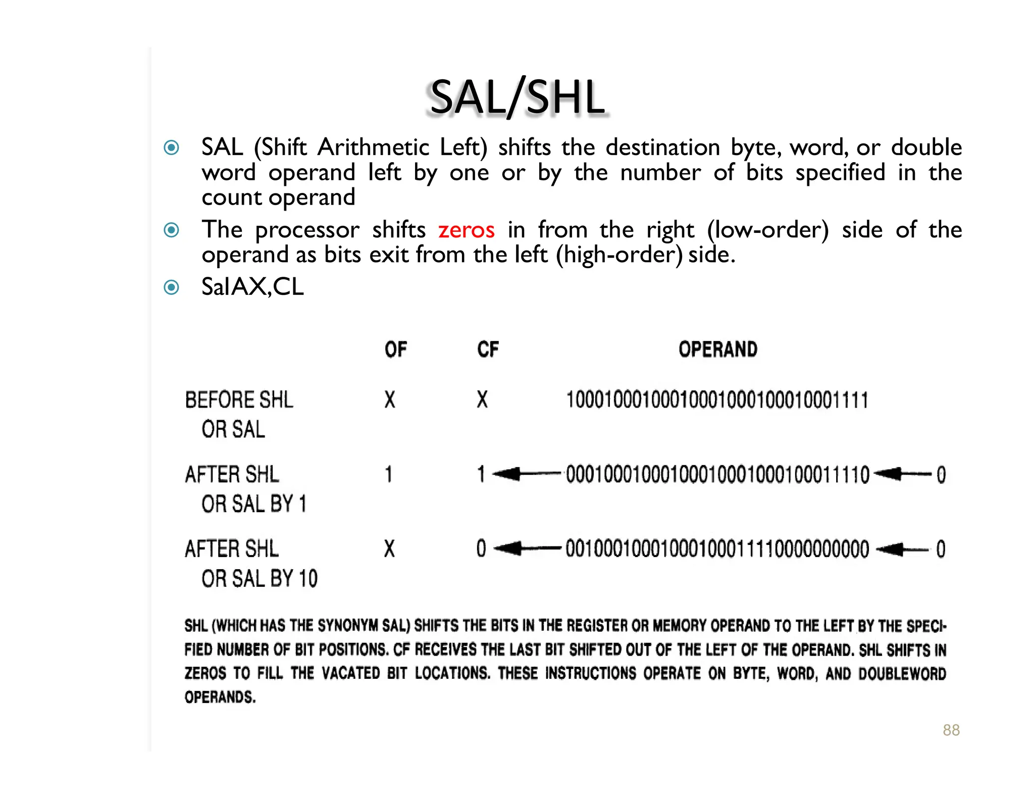
SAL/SHL
� SAL (ShiftArithmetic Left) shifts the destination byte, word, or double
word operand left by one or by the number of bits specified in the
count operand
� The processor shifts zeros in from the right (low-order) side of the
operand as bits exit from the left (high-order) side.
� SalAX,CL
88
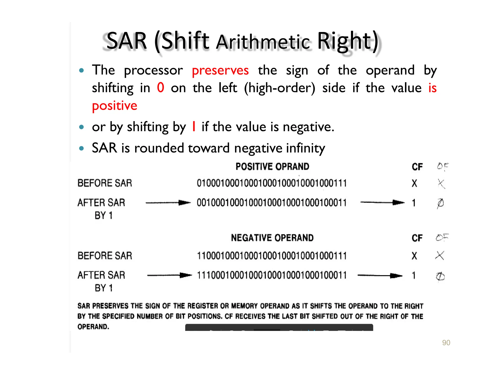
SAR (Shift ArithmeticRight)
� The processor preserves the sign of the operand by
shifting in 0 on the left (high-order) side if the value is
positive
� or by shifting by 1 if the value is negative.
� SAR is rounded toward negative infinity
90
91.
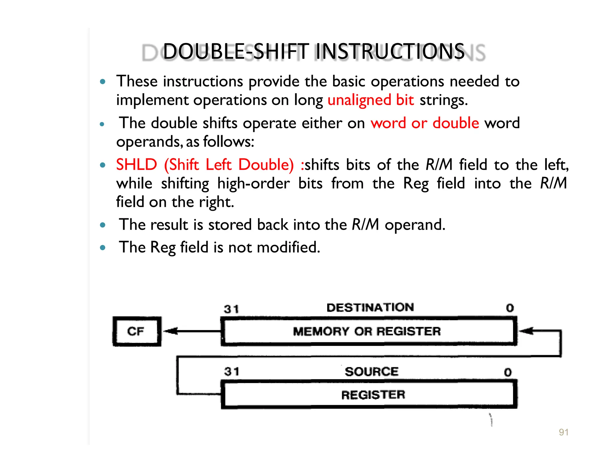
DOUBLE-SHIFT INSTRUCTIONS
� Theseinstructions provide the basic operations needed to
implement operations on long unaligned bit strings.
� The double shifts operate either on word or double word
operands,as follows:
� SHLD (Shift Left Double) :shifts bits of the R/M field to the left,
while shifting high-order bits from the Reg field into the R/M
field on the right.
� The result is stored back into the R/M operand.
� The Reg field is not modified.
91
92.
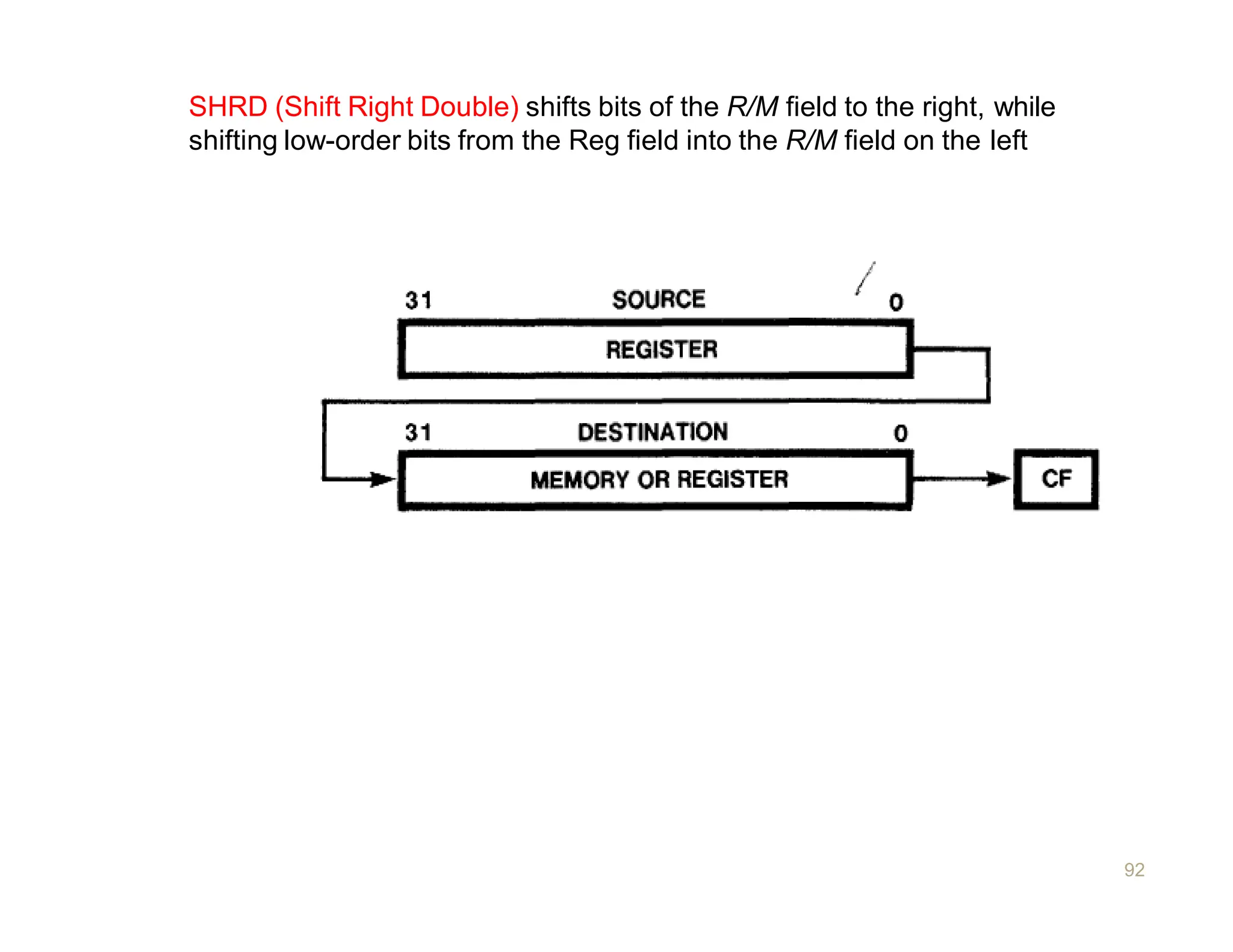
SHRD (Shift RightDouble) shifts bits of the R/M field to the right, while
shifting low-order bits from the Reg field into the R/M field on the left
92
93.
ROTATE INSTRUCTIONS
93
� Rotateinstructions allow bits in bytes,words, and double
words to be rotated.
� Bits rotated out of an operand are not lost as in a shift,
but are "circled" back into the other "end" of the operand.
� Rotates affect only the carry and overflow flags.
� CF may act as an extension of the operand.
� CF always contains the value of the last bit rotated out.
94.
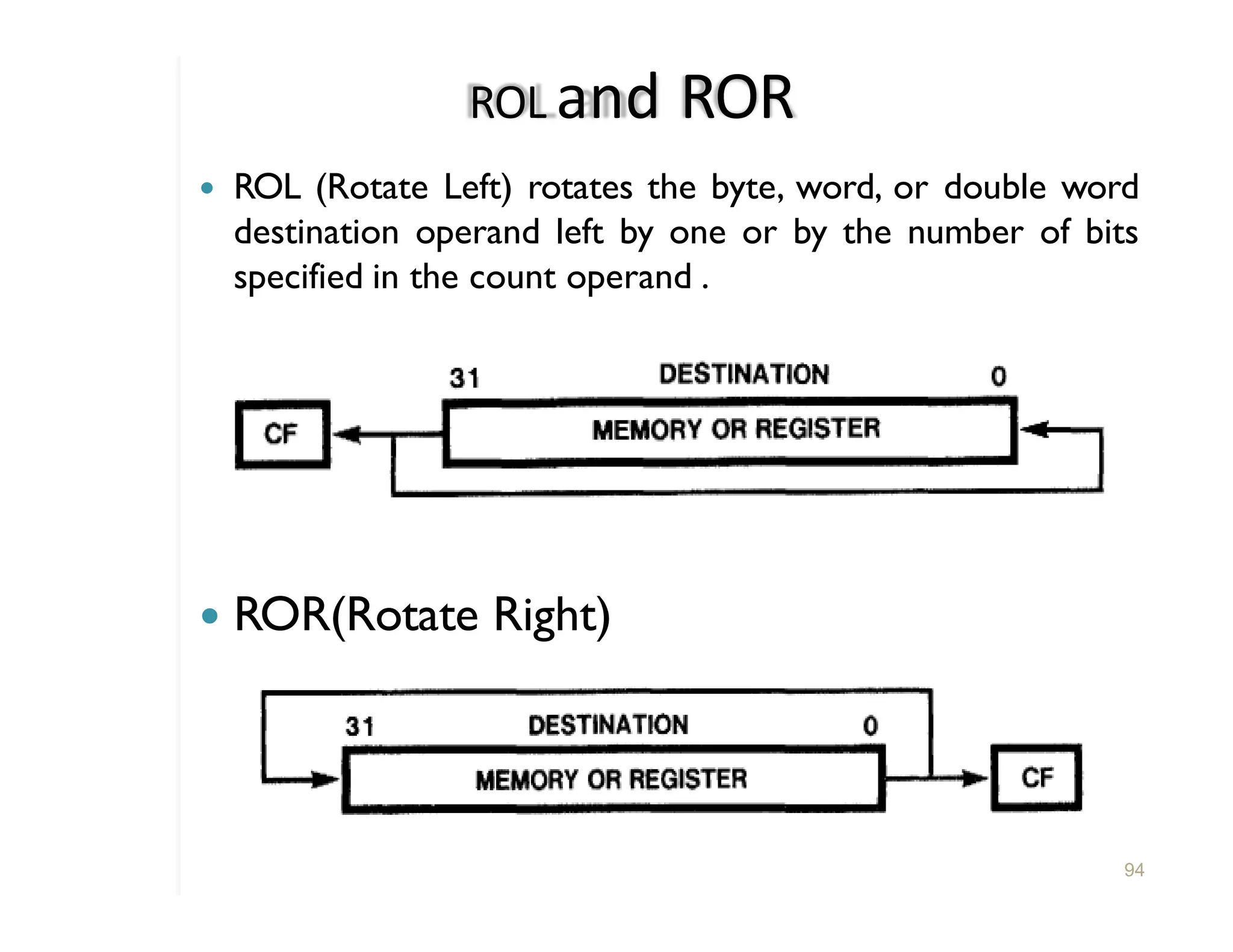
ROL and ROR
�ROL (Rotate Left) rotates the byte, word, or double word
destination operand left by one or by the number of bits
specified in the count operand .
� ROR(Rotate Right)
94
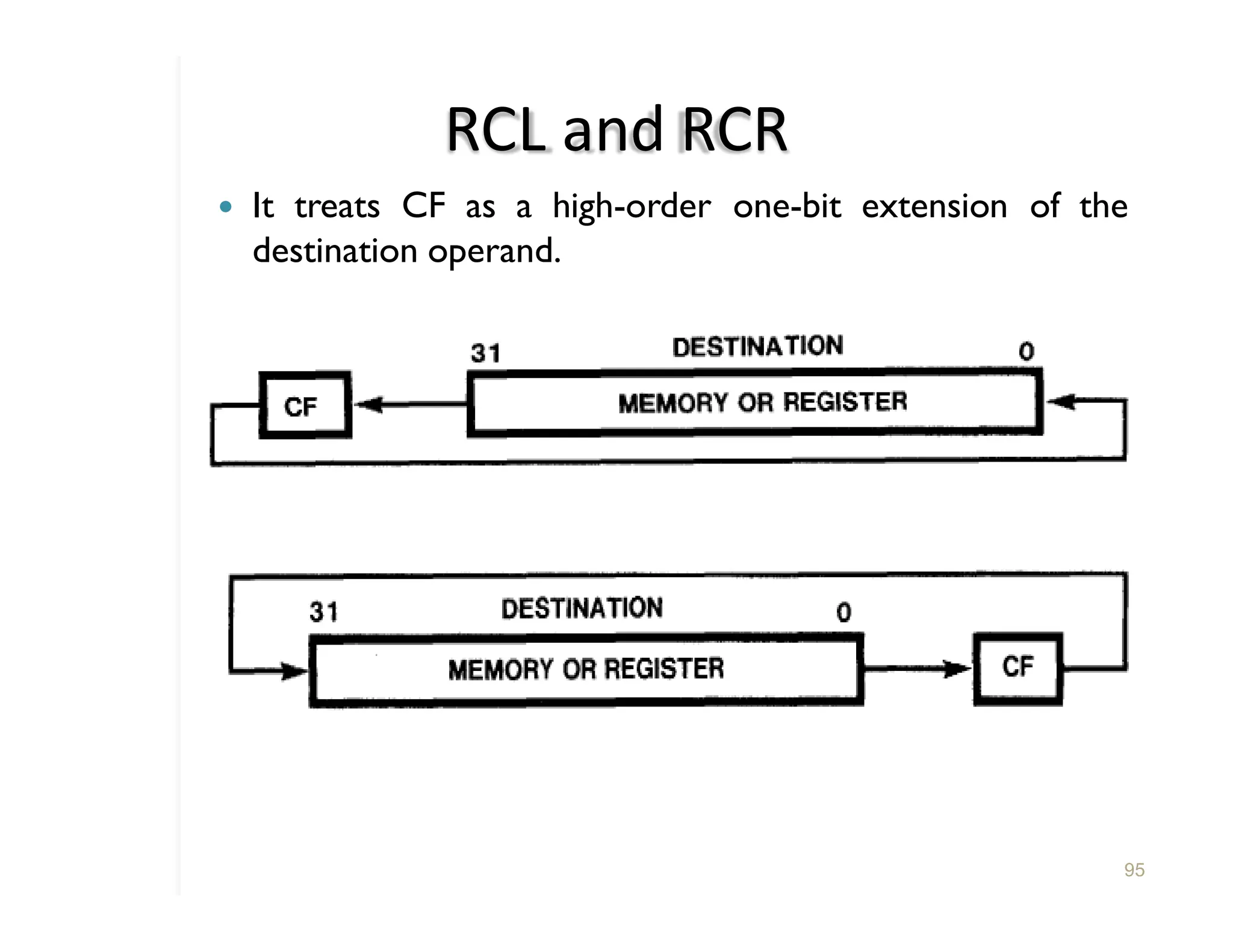
95.
RCL and RCR
�It treats CF as a high-order one-bit extension of the
destination operand.
95
96.
CONTROL TRANSFERINSTRUCTIONS
96
� UnconditionalTransferInstructions:
�JMP- JMP is a one-way transfer of execution; it does not
save a return address on the stack.
� CALL- activates an out-of-line procedure, saving on the
stack the address of the instruction following the CALL
for later use by a RET (Return) instruction.***stack
� RET
-terminates the execution of a procedure and
transfers control through a back-link on the stack to the
program that originally invoked the procedure.*** back
link on the stack EIP
� IRET
- returns control to an interrupted procedure.IRET
differs from RET in that it also pops the flags from the
stack into the flags register.
Conditional
98
� LOOP
� LOOPE(Loop While Equal) and LOOPZ (Loop While
Zero)
These instructions automatically decrement the ECX
register before testing ECX and ZF for the branch
conditions.
ECX=0 and ZF=0 ignore
� LOOPNE (LoopWhile Not Equal) and LOOPNZ (Loop
While Not Zero)
ECX=0 and ZF=1 ignore
� JCXZ (Jump if ECX Zero) branches to the label specified
in the instruction if it finds a value of zero in ECX.
99.
Software Generated Interrupts
99
�INT n (Software Interrupt) activates the interrupt
service routine that corresponds to the number coded
within the instruction. The interrupt service routine
terminates with an IRET instruction that returns control to
the instruction that follows INT.
� INTO (Interrupt on Overflow) invokes interrupt 4 if
OF is set.
� BOUND (Detect Value Out of Range) verifies that
the signed value contained in the specified register lies
within specified limits. An interrupt (INT 5) occurs if the
value contained in the register is less than the lower bound
or greater than the upper bound.
100.
STRING AND CHARACTERTRANSLATION
INSTRUCTIONS
100
�1. A set of primitive string operations
� MOVS — Move String
� CMPS — Compare string
� SCAS — Scan string
� LODS — Load string
� STOS — Store string
�2. Indirect, indexed addressing, with automatic incrementing or decrementing of
the indexes.
Indexes:
� ESI — Source index register
� EDI — Destination index register
� Control flag:
� DF — Direction flag
� Control flag instructions:
� CLD Clear direction flag instruction
� STD — Set direction flag instruction
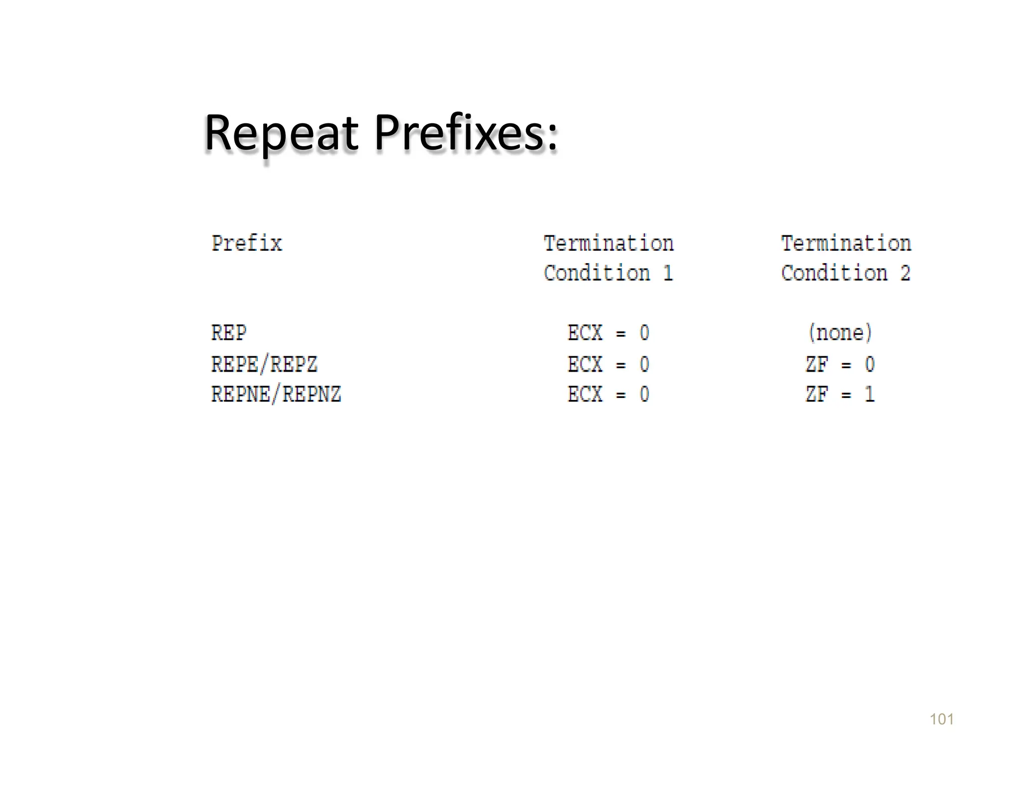
� 3. Repeat prefixes
� REP Repeat while ECX not zero
� REPE/REPZ Repeat while equal or zero
� REPNE/REPNZ Repeat while not equal or not zero
Indexing and Directionflag
Control
102
� The addresses of the operands of string primitives are
determined by the ESI and EDI registers.
� ESI points to source operands. By default, ESI refers to a
location in the segment indicated by the DS segment
register. A segment-override prefix may be used, however,
to cause ESI to refer to CS,SS,ES,FS,or GS.
� EDI points to destination operands in the segment
they are
indicated by ES; no segment override is possible.
� The direction flag determines whether
incremented or decremented.
103.
String Instructions
103
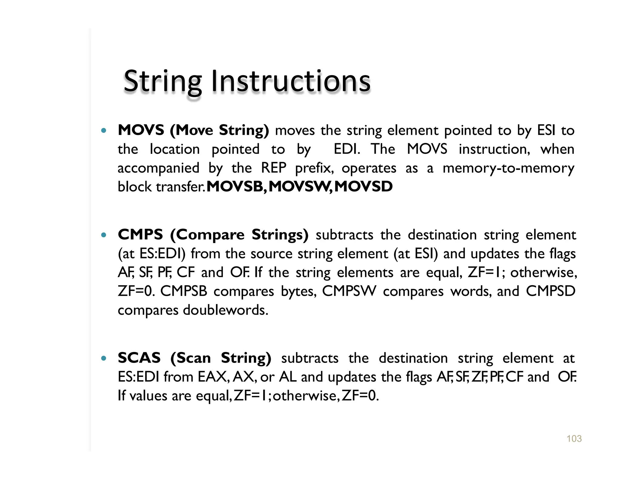
� MOVS(Move String) moves the string element pointed to by ESI to
the location pointed to by EDI. The MOVS instruction, when
accompanied by the REP prefix, operates as a memory-to-memory
block transfer.MOVSB,MOVSW,MOVSD
� CMPS (Compare Strings) subtracts the destination string element
(at ES:EDI) from the source string element (at ESI) and updates the flags
AF, SF, PF, CF and OF. If the string elements are equal, ZF=1; otherwise,
ZF=0. CMPSB compares bytes, CMPSW compares words, and CMPSD
compares doublewords.
� SCAS (Scan String) subtracts the destination string element at
ES:EDI from EAX, AX, or AL and updates the flags AF,SF,ZF,PF
,CF and OF
.
If values are equal,ZF=1;otherwise,ZF=0.
104.
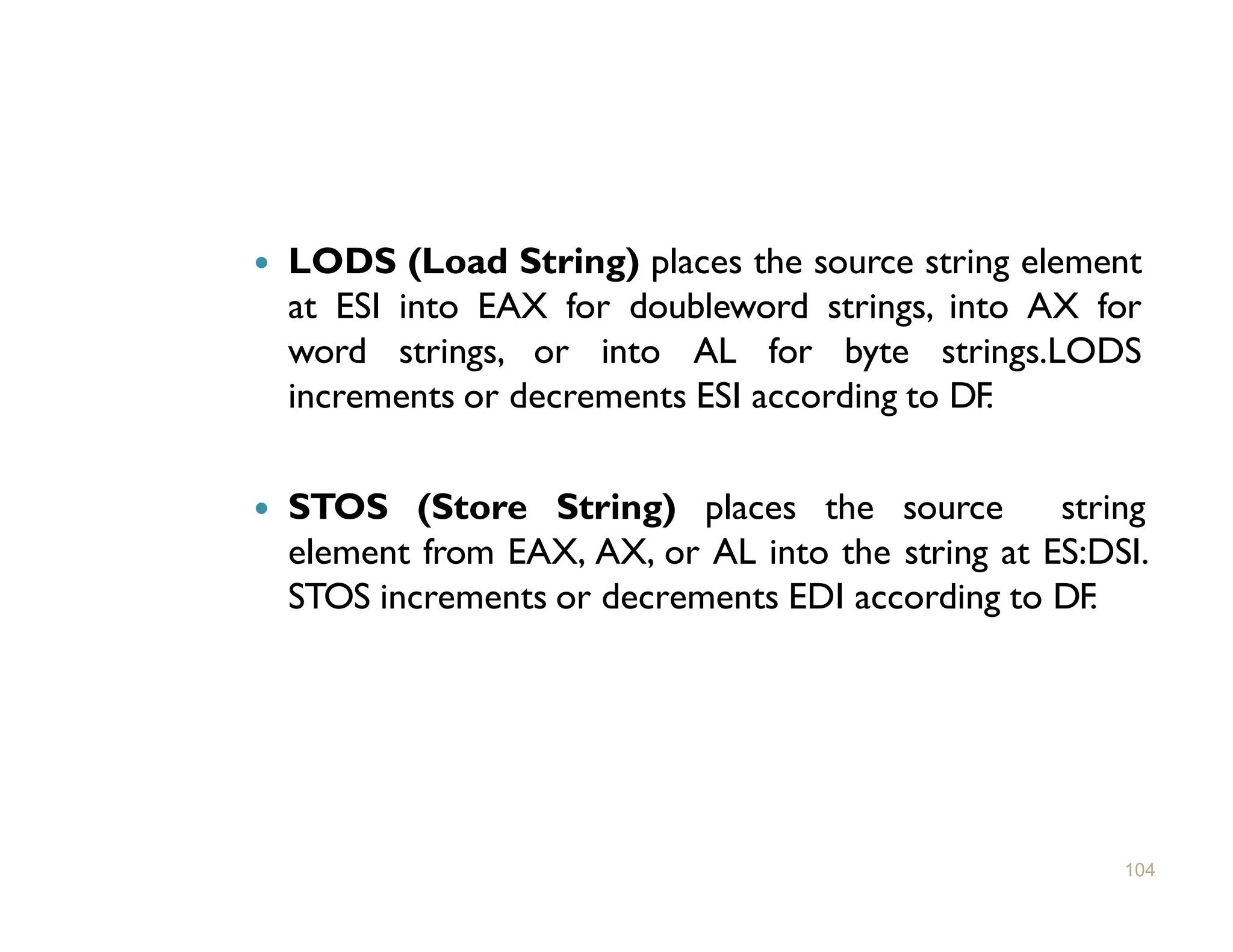
� LODS (LoadString) places the source string element
at ESI into EAX for doubleword strings, into AX for
word strings, or into AL for byte strings.LODS
increments or decrements ESI according to DF.
� STOS (Store String) places the source string
element from EAX, AX, or AL into the string at ES:DSI.
STOS increments or decrements EDI according to DF.
104
105.
Instructions for Block
StructuredLanguages
105
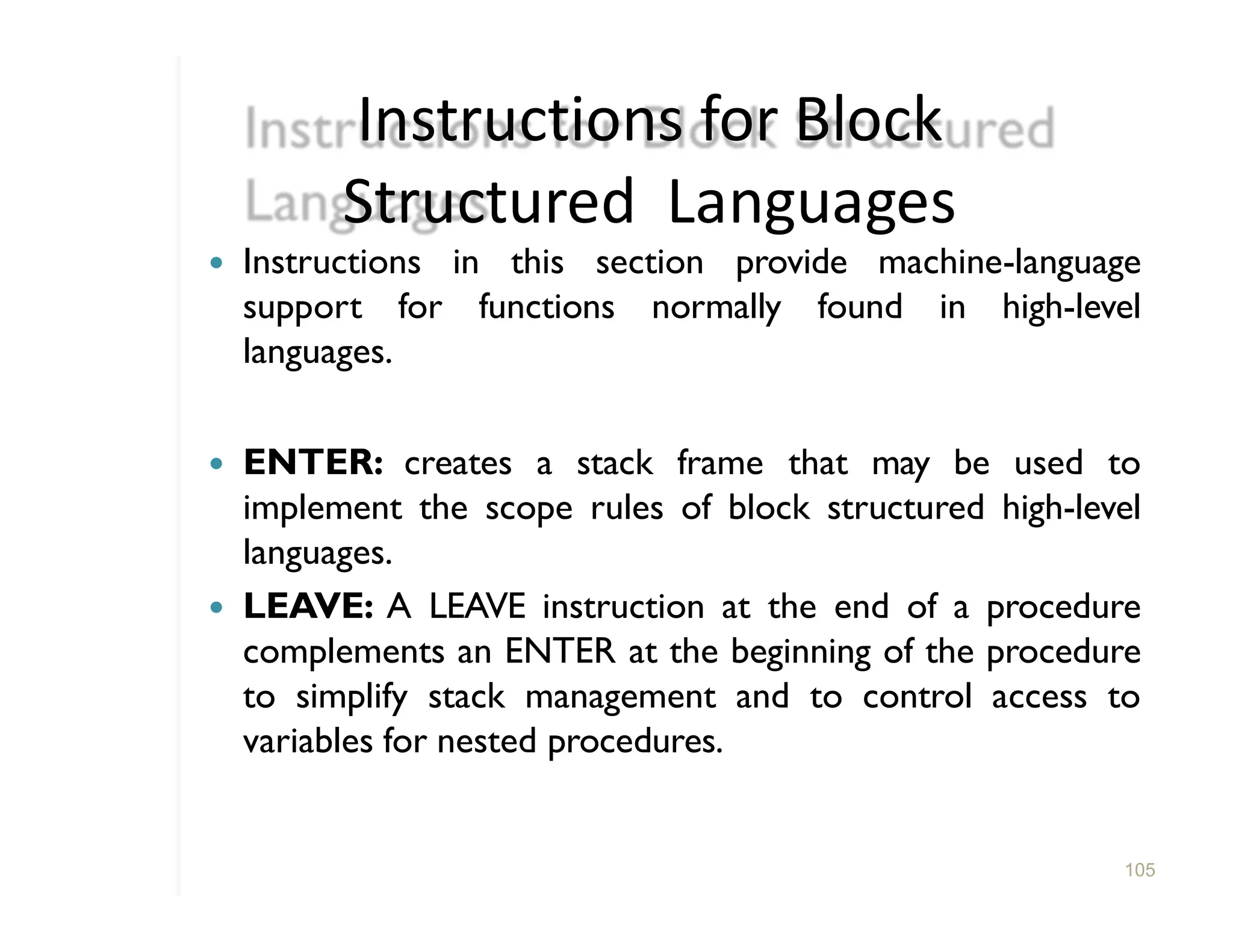
� Instructions in this section provide machine-language
support for functions normally found in high-level
languages.
� ENTER: creates a stack frame that may be used to
implement the scope rules of block structured high-level
languages.
� LEAVE: A LEAVE instruction at the end of a procedure
complements an ENTER at the beginning of the procedure
to simplify stack management and to control access to
variables for nested procedures.
106.
Enter
106
� Includes twoparameters. The first parameter specifies the
number of bytes of dynamic storage to be allocated on the
stack for the routine being entered. The second parameter
corresponds to the lexical nesting level (0-31) of the
routine.
� The specified lexical level determines how many sets of
stack frame pointers the CPU copies into the new stack
frame from the preceding frame.
� This list of stack frame pointers is sometimes called the
display.
� EX. ENTER 2048,3
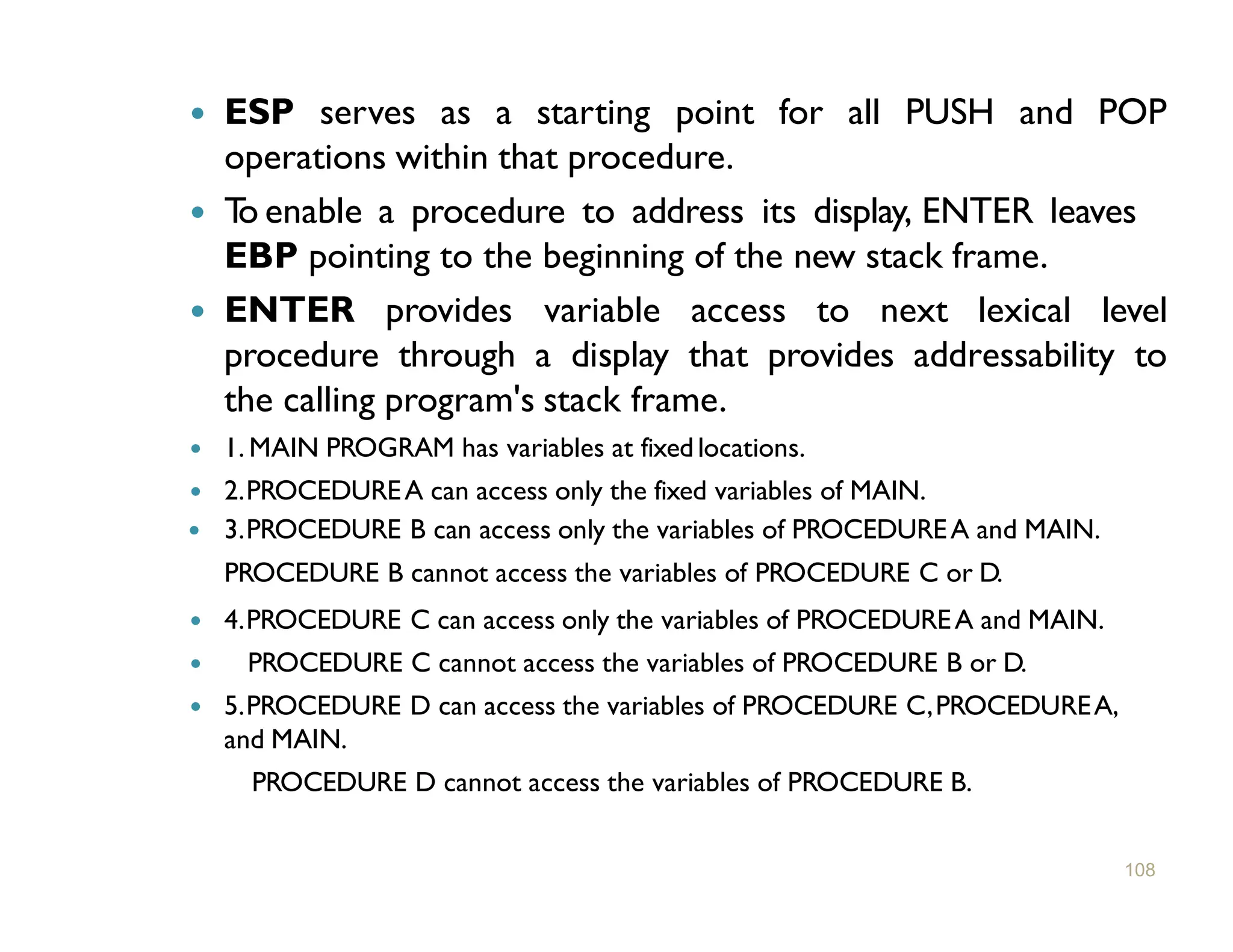
� ESP servesas a starting point for all PUSH and POP
operations within that procedure.
� T
o enable a procedure to address its display, ENTER leaves
EBP pointing to the beginning of the new stack frame.
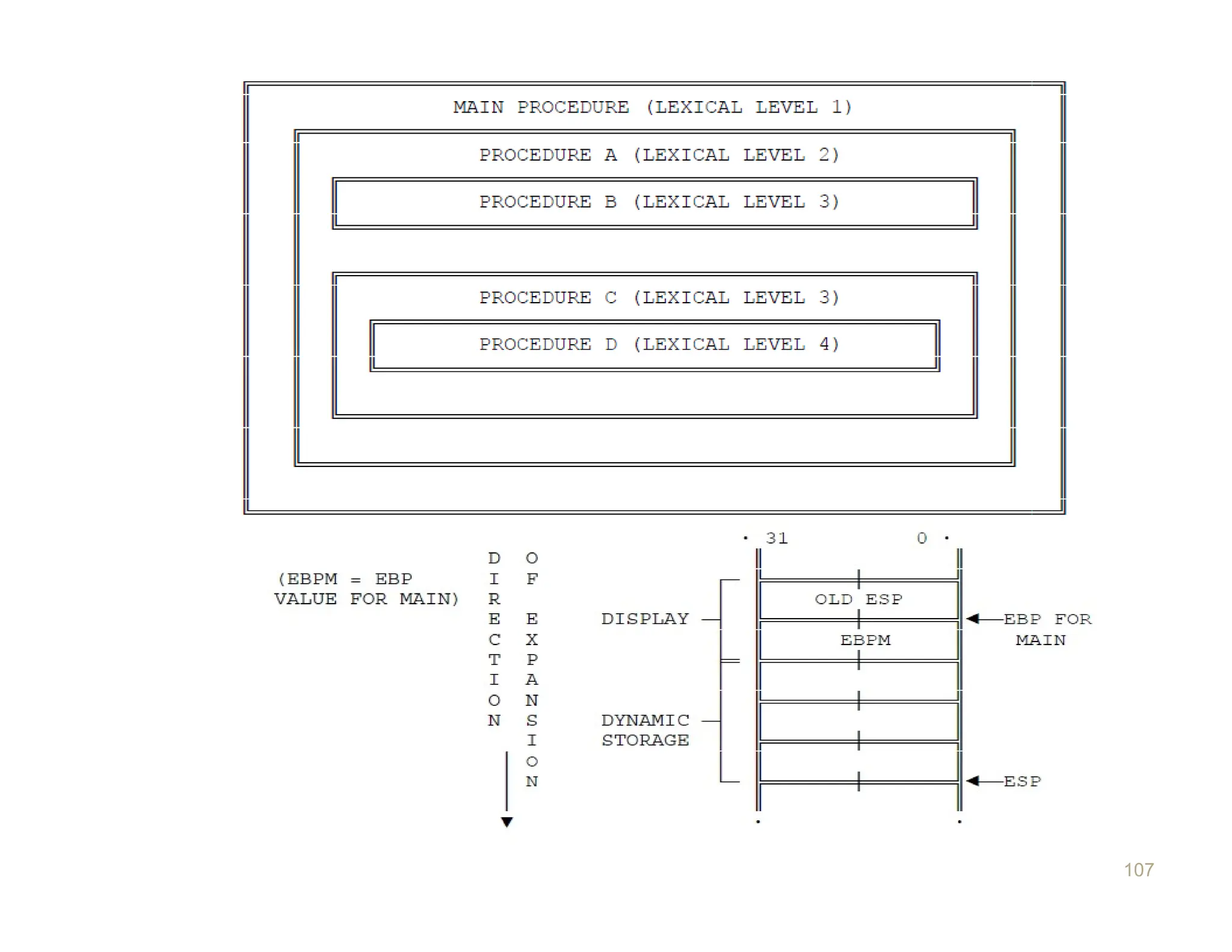
� ENTER provides variable access to next lexical level
procedure through a display that provides addressability to
the calling program's stack frame.
� 1. MAIN PROGRAM has variables at fixedlocations.
� 2.PROCEDUREA can access only the fixed variables of MAIN.
� 3.PROCEDURE B can access only the variables of PROCEDUREA and MAIN.
PROCEDURE B cannot access the variables of PROCEDURE C or D.
� 4.PROCEDURE C can access only the variables of PROCEDUREA and MAIN.
� PROCEDURE C cannot access the variables of PROCEDURE B or D.
� 5.PROCEDURE D can access the variables of PROCEDURE C,PROCEDUREA,
and MAIN.
PROCEDURE D cannot access the variables of PROCEDURE B.
108
109.
� Procedure Acan access variables in MAIN since
MAIN is at level 1. Therefore the base for the
dynamic storage for MAIN is at [EBP-2].
� All dynamic variables for MAIN are at a fixed
offset from this value.
109
110.
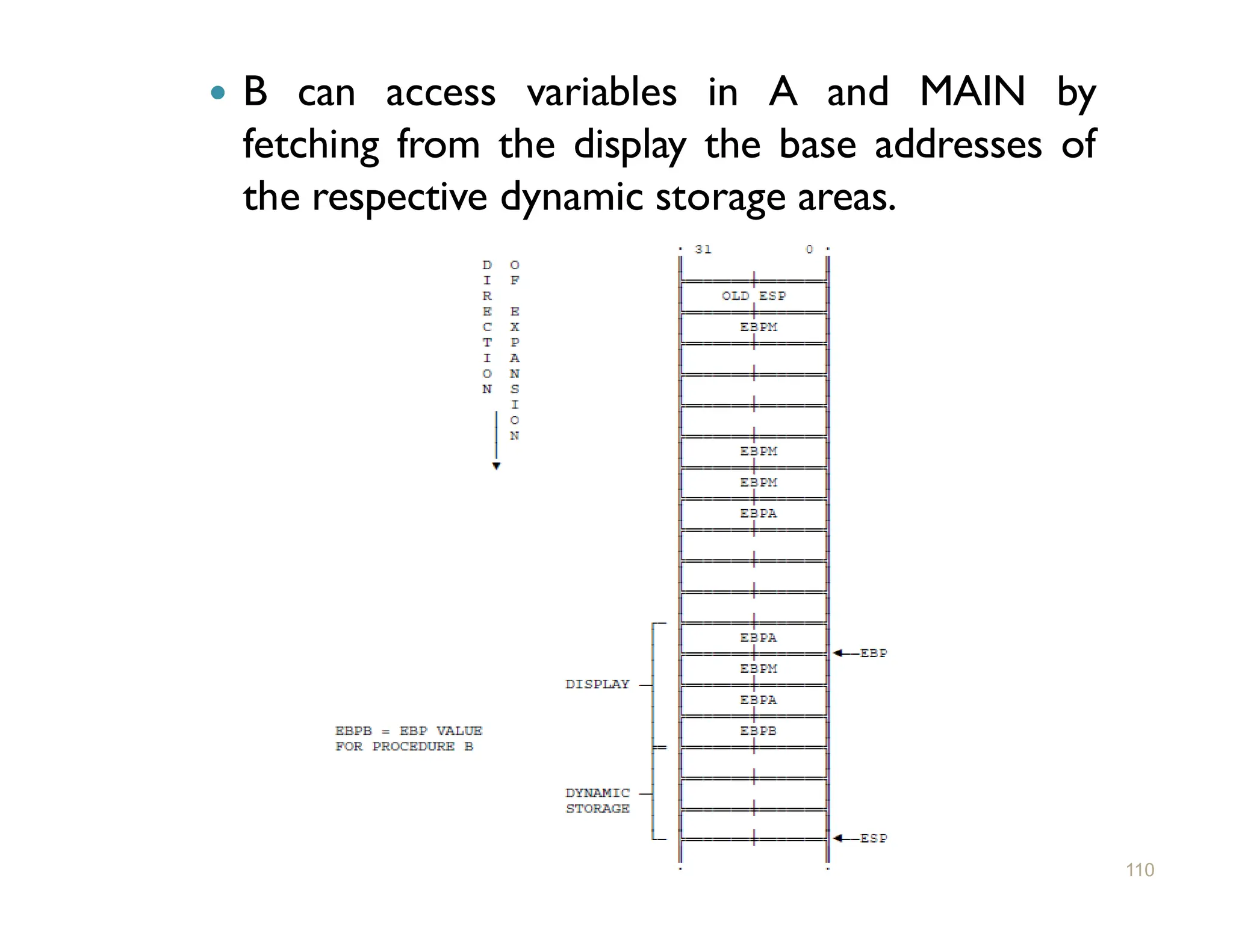
� B canaccess variables in A and MAIN by
fetching from the display the base addresses of
the respective dynamic storage areas.
110
111.
LEAVE
111
� LEAVE (LeaveProcedure) reverses the action
of the previous ENTER instruction. The LEAVE
instruction does not include any operands.
� LEAVE copies EBP to ESP to release all stack
space allocated to the procedure by the most
recent ENTER instruction.
� Then LEAVE pops the old value of EBP from the
stack.
112.
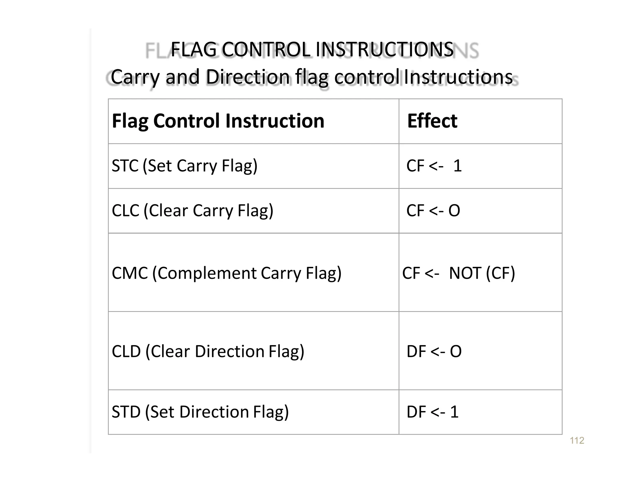
FLAG CONTROL INSTRUCTIONS
Carryand Direction flag controlInstructions
112
Flag Control Instruction Effect
STC (Set Carry Flag) CF <- 1
CLC (Clear Carry Flag) CF <- O
CMC (Complement Carry Flag) CF <- NOT (CF)
CLD (Clear Direction Flag) DF <- O
STD (Set Direction Flag) DF <- 1
113.
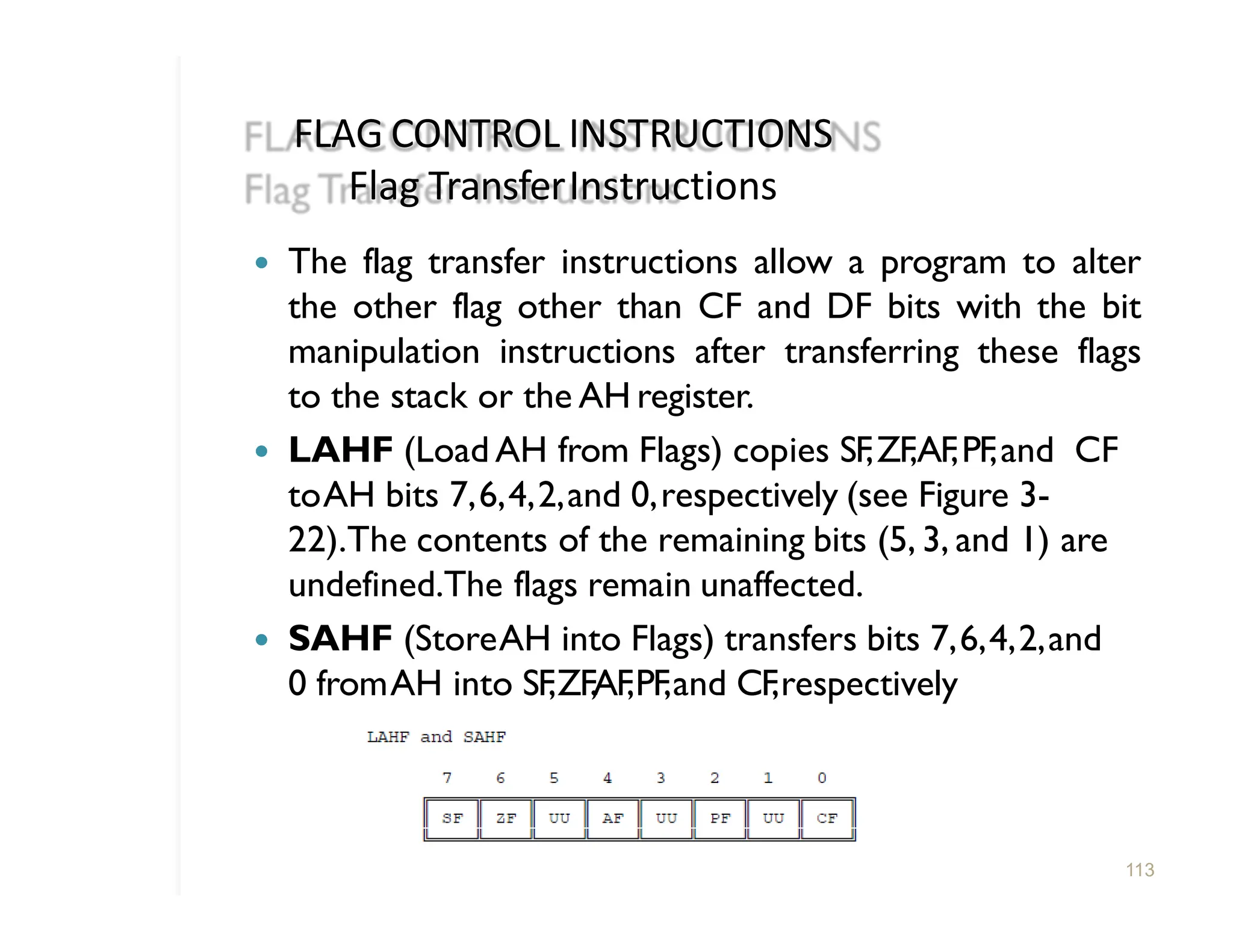
FLAG CONTROL INSTRUCTIONS
FlagTransferInstructions
� The flag transfer instructions allow a program to alter
the other flag other than CF and DF bits with the bit
manipulation instructions after transferring these flags
to the stack or the AH register.
� LAHF (Load AH from Flags) copies SF,ZF,AF,PF,and CF
toAH bits 7,6,4,2,and 0,respectively (see Figure 3-
22).The contents of the remaining bits (5, 3, and 1) are
undefined.The flags remain unaffected.
� SAHF (StoreAH into Flags) transfers bits 7,6,4,2,and
0 fromAH into SF,ZF,AF,PF,and CF,respectively
113
114.
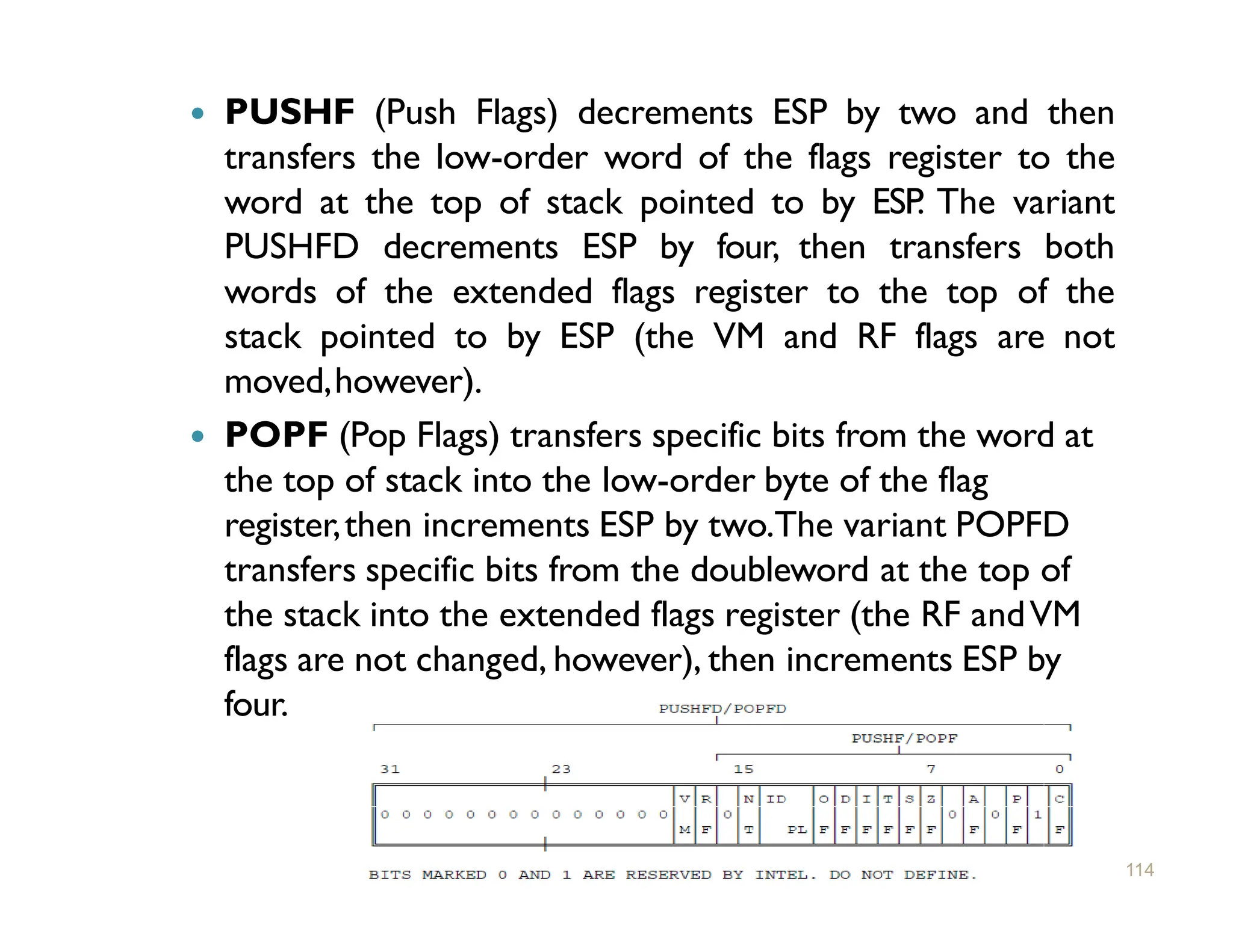
� PUSHF (PushFlags) decrements ESP by two and then
transfers the low-order word of the flags register to the
word at the top of stack pointed to by ESP. The variant
PUSHFD decrements ESP by four, then transfers both
words of the extended flags register to the top of the
stack pointed to by ESP (the VM and RF flags are not
moved,however).
� POPF (Pop Flags) transfers specific bits from the word at
the top of stack into the low-order byte of the flag
register,then increments ESP by two.The variant POPFD
transfers specific bits from the doubleword at the top of
the stack into the extended flags register (the RF andVM
flags are not changed, however), then increments ESP by
four.
114
115.
COPROCESSOR INTERFACE INSTRUCTIONS
115
�The 80386 also has features to support emulation of the
numeric coprocessor when the coprocessor is absent.
� ESC (Escape) : Used by Coprocessor is a 5-bit
sequence that begins the opcodes that identify floating
point numeric instructions.
� ESC pattern tells 80386 to send the opcode and addresses
of operands to numeric coprocessor.
� The numeric coprocessor uses the escape instructions to
perform high-performance, high-precision floating point
arithmetic.
116.
COPROCESSOR INTERFACE
INSTRUCTIONS
116
� WAIT(Wait)
� Suspends (80386) program execution until the
80386 CPU detects that the BUSY pin is inactive.
� This condition indicates that the coprocessor has
completed its processing and CPU may obtain
result.
117.
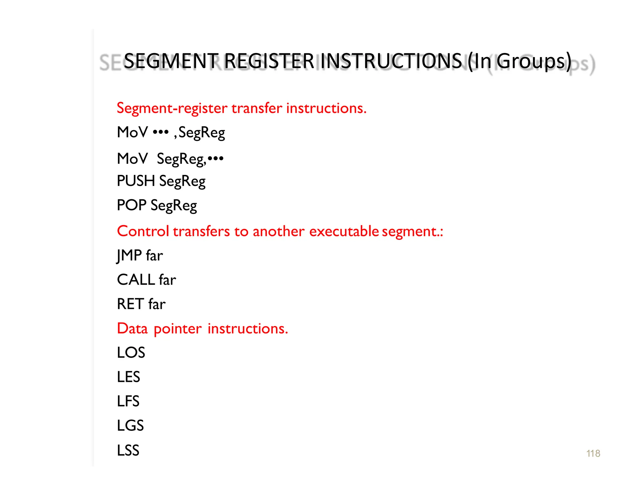
SEGMENT REGISTER INSTRUCTIONS(In Groups)
Segment-register transfer instructions.
MoV ••• ,SegReg
MoV SegReg,•••
PUSH SegReg
POP SegReg
Control transfers to another executable segment.:
JMP far
CALL far
RET far
Data pointer instructions.
LOS
LES
LFS
LGS
LSS 118
118.
Data Pointer
Instructions
118
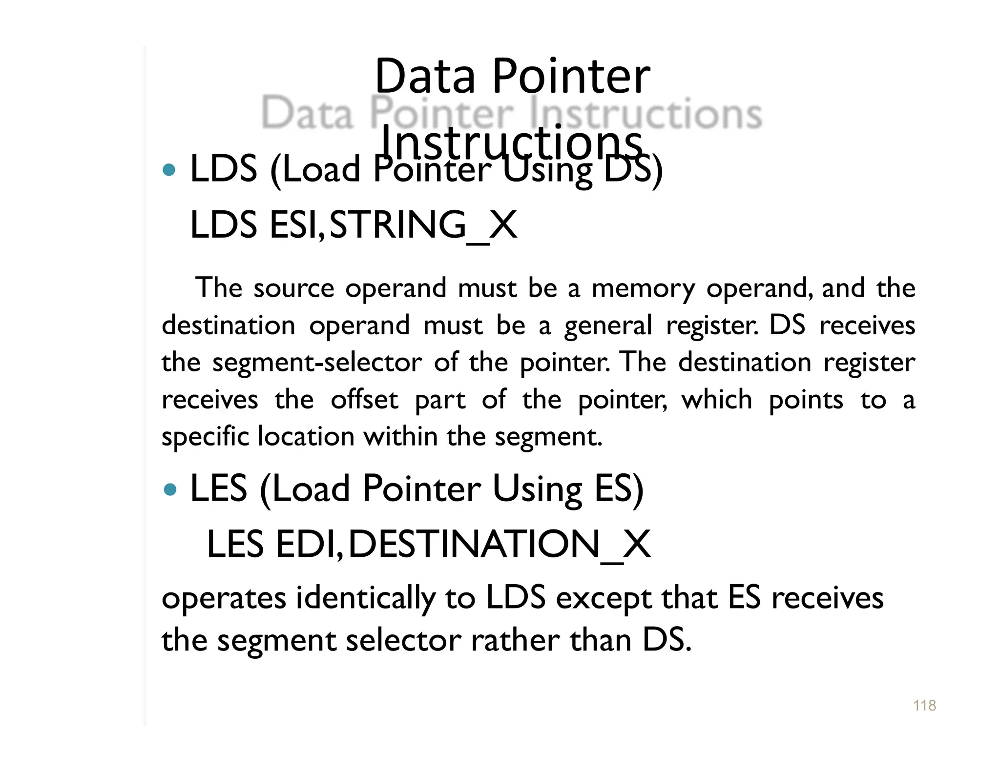
� LDS(Load Pointer Using DS)
LDS ESI,STRING_X
The source operand must be a memory operand, and the
destination operand must be a general register. DS receives
the segment-selector of the pointer. The destination register
receives the offset part of the pointer, which points to a
specific location within the segment.
� LES (Load Pointer Using ES)
LES EDI,DESTINATION_X
operates identically to LDS except that ES receives
the segment selector rather than DS.
119.
� LFS (LoadPointer Using FS)
Operates identically to LDS except that FS
receives the segment selector rather than
DS.
� LGS (Load Pointer Using GS)
Operates identically to LDS except that GS
receives the segment selector rather than
DS.
� LSS (Load Pointer Using SS)
Operates identically to LDS except that SS
receives the segment selector rather than
DS.
119
120.
Miscellaneous
Instructions
120
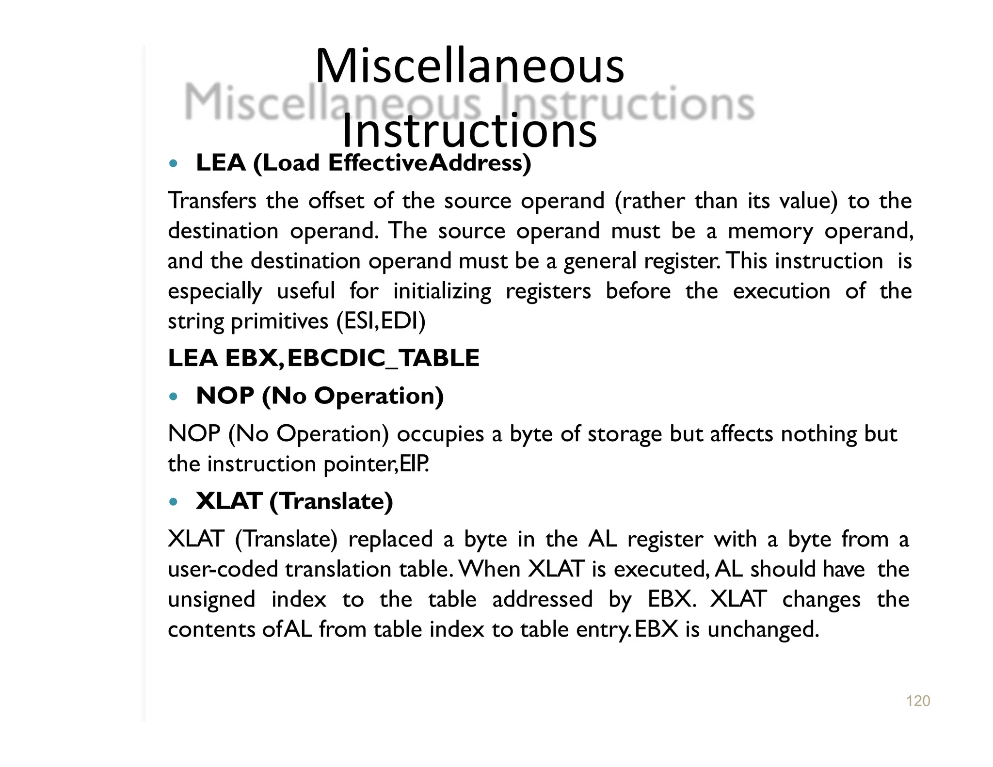
� LEA (LoadEffectiveAddress)
Transfers the offset of the source operand (rather than its value) to the
destination operand. The source operand must be a memory operand,
and the destination operand must be a general register. This instruction is
especially useful for initializing registers before the execution of the
string primitives (ESI,EDI)
LEA EBX,EBCDIC_TABLE
� NOP (No Operation)
NOP (No Operation) occupies a byte of storage but affects nothing but
the instruction pointer,EIP.
� XLAT (Translate)
XLAT (Translate) replaced a byte in the AL register with a byte from a
user-coded translation table. When XLAT is executed, AL should have the
unsigned index to the table addressed by EBX. XLAT changes the
contents ofAL from table index to table entry.EBX is unchanged.
121.
Feedbac
k
121
� Teaching Method
�Am I audible?
� Am I interactive with you?
� Study Material (PPT,Notes etc.)
� Any Suggestions are welcome…
122.
Solve
122
� Explain 80386Architecture
�Write a procedure for „ASCII to HEX
‟
and „HEX to ASCII‟Conversion.
� List and Explain General Purpose Registers.
� Explain following flags from EFLAG register
1.VM 2.IOPL 3.RF
� Explain following instructions
1. XOR 2.PUSHA 3.CALL 4.JMP


![� Procedure A can access variables in MAIN since
MAIN is at level 1. Therefore the base for the
dynamic storage for MAIN is at [EBP-2].
� All dynamic variables for MAIN are at a fixed
offset from this value.
109](https://image.slidesharecdn.com/module4-250502063137-be781ea5/75/80386-Basic-Programming-Model-and-Application-109-2048.jpg)


![� Procedure A can access variables in MAIN since
MAIN is at level 1. Therefore the base for the
dynamic storage for MAIN is at [EBP-2].
� All dynamic variables for MAIN are at a fixed
offset from this value.
109](https://crownmelresort.com/image.slidesharecdn.com/module4-250502063137-be781ea5/75/80386-Basic-Programming-Model-and-Application-109-2048.jpg)